

Page 1
micros
®
Systems, Inc.
PC Workstation
Ultra
Setup Guide
Copyright 1998, 1999
By MICROS Systems, Inc.
Beltsville, Maryland USA
All Rights Reserved
Part Number 100016-103 (2nd Edition)
Page 2

Declarations
Warranties
Trademarks
Although the best efforts are made to ensure that the
information contained in this manual is complete and correct,
MICROS Systems, Inc. makes no warranty of any kind with
regard to this material, including but not limited to the implied
warranties of marketabilit y and fitness for a part icular purpose .
Information in this manual is subject to change without notice.
MICROS Systems, Inc. shall not be liable for errors contained
herein or for incidental or consequential damages in connection
with the furnishing, performance, or use of this material.
MICROS is a registered trademark of MICRO S Systems, Inc
Intel, Pentium, and MMX are registered trademarks of Intel Corporation
IBM, AT, XT, VGA, EGA, XGA, PS/2, and PC-DOS are registered trad emarks
of International Business Machines Corporation
Microsoft, Windows, Windows 95 Windows 98, Windows NT, Windows Sound
System, and Microsoft SQL Server are trademarks of Microsoft Corporation in
the United States of America and in other countrie s.
Intel, Pentium, and MMX are registered trademarks of Intel Corporation.
PCnet, AMD, the AMD logo, and combinations thereof are trademarks of
Advanced Micro Devices, Inc
Chips & Technologies is a registered trademark of Chips & Technologies, Inc
Adobe and FrameMaker are trademarks of Adobe Systems, Incorporated
CorelDraw is a registered trademark of the Corel Corporation
Printing History
New editions of this manual incorporate new and changed
material since the previous edition. Minor corrections and
updates may be incorporated into reprints of t he current edition
without changing the date or edition number.
1st Edition - October 1998
2nd Edition - October 1999
ii
Page 3

Index
Table of Contents
Preface
Purpose ........................................................................................x
Who Should Use This Manual? ..................................................x
Related Manuals ..........................................................................x
Symbols.........................................................................................xii
Document Design and Production ..............................................xii
Chapter 1: The System
What is the PC Workstation?..............................................................1-2
Profile............................................................................................1-2
Display and Touchscreen ............................................................1-3
System Boards..............................................................................1-3
PCWS Accesso ri e s . ............... ............................. ................ ...........1-4
Expansion Capabilities ...............................................................1-4
Diagnostics Utilities .................................................................... 1-4
PCWS API .................... ............. ............... ................ ............... ..... 1-4
Specifications ............................................................................... 1-5
Approvals .....................................................................................1-7
Care and Handling..............................................................................1-8
Environmental Requirements ........................ ............................1-8
Cleaning ....................................................................................... 1-9
Transporting the Workstation ....................................................1-9
Connecting the Basic System..............................................................1-10
Rear Connector Panel .................................................................1-10
External AC Adapter ...................................................................1-12
PCWS Floppy Diskette Unit .......................................................1-13
PC Keyboard ................................................................................1-15
PS/2 Mouse ..................................................................................1-16
Remote Custom e r Di sp l ay ....... .. ............................. ............... .....1-17
Chapter 2: Setup Utility
Starting the PhoenixBIOS Setup Utility ........................................... 2-2
Main Menu................................ .. .. ...................................................... . 2-4
Advanced Menu ... .. .. ................ ............................. ............... ................ 2-5
Security Menu......................................................................................2-10
Power Menu................ .. ............... ................ ............... .........................2-11
Boot Menu............................................................................................2-13
Exit Menu ................... .. .. ................ ............... ............................. .........2-14
PCWS Ultra Setup Guide iii
Page 4

Table of Contents
Chapter 3: PCWS Ultra Hardware Configuration
Remove the Cover................................................................................3-2
Removing/Securing the PCWS Low Profile Cover .....................3-2
Removing/Securing the PCWS AD Cover ..................................3-3
What’s Inside? .....................................................................................3-4
The PC Worksta t io n Ul t ra As s embly ............... ................ ..........3-4
Ultra System Board Components ...............................................3-6
Ultra System Board Connectors .................................................3-10
Ultra System Board Jumpers and DIP Switches ......................3-11
Ultra System Board Memory Map .............................................3-12
Ultra System Board IO Port Map ..............................................3-13
Ultra System Board IRQ Assignments ......................................3-14
Processor..............................................................................................3-15
Main Memory .............................................. .. .. .. .. ................................3-21
Hard Disk ................. ... .. ............... ................ ............................. ..........3-24
Customer Displ a y........ .. ............... ................ ............................. ..........3-29
LCD Configura t i o n........ .. ............................. ............... ................ ........3-32
Expansion Card Installation ..............................................................3-34
Index
Chapter 4: PCWS Ultra Diagnostics
Basic Troubleshooting......................................................................... 4-2
Diagnostics LE D s ............ .. ................ ............... ................ ................... 4-4
POST Error Messages......................................................................... 4-6
POST Error Beep Codes...................................................................... 4-7
Glossary
Appendix A: Equipment Dimensions
Overview.............................................................................................. A-2
PC Workstation - Low Profile............................................................. A-3
PC Workstation - Adjustable Display .................................. .. ............ A-4
PC Workstation Floppy Diskette Unit............................................... A-5
PCWS LP Adjustable Stand ........................................... .. .. .. .. ............ A-6
PCWS Remote Po le Di sp la y..... .. .. ................ ............... ........................ A-7
Cash Drawer........................................................................................ A-8
Cash Drawer, Low Profile................................................................... A-9
Appendix B: Connector and Cable Diagrams
Overview..............................................................................................B-2
PCWS Ultra Con n ec t or s ................. .. .. ............... ............................. ....B-3
LCC Port ............................ .. .. ......................................................B-3
RS232 Interface ...........................................................................B-3
Parallel Port Connector ....................................................... .. .....B-4
iv
Page 5

Index
Cash Drawer Connectors ............................................................B-5
PS/2 Keyboard Connector ...........................................................B-5
Power +24VDC Connector ..........................................................B-6
Remote Customer Display ..........................................................B-6
Ethernet Connector .....................................................................B-7
IDN Device Port ..................................................................................B-8
8-Pin to 6-Pin Hook-up RS422 Cable (300319-001)...........................B-9
Cash Drawer Extension Cable .................................................. .. .. .. .. .B-10
Table of Contents
Appendix C: FCC/DOC Statement
Index
PCWS Ultra Setup Guide v
Page 6

Table of Contents
List Of Figures
Figure 1-1: The PCWS Low Profile and Adjustable Display ..........1-2
Figure 1-2: The PCWS Ultra Rear Connector Panel .......................1-10
Figure 1-3: Connecting the External AC Adapter ...........................1-12
Figure 1-4: Installing the PCWS Floppy Diskette Unit ..................1-13
Figure 1-5: Connecting a PC Keyboard ............................................1-15
Figure 1-6: Remote Pole Display Assembly .....................................1-18
Figure 3-1: Removing/Securing the PCWS Low Profile Cover .......3-2
Figure 3-2: Removing/Securing the PCWS AD Cover ......................3-3
Figure 3-3: The PC Workstation Ultra Assembly .............................3-4
Figure 3-4: The Ultra System Board Components ...........................3-6
Figure 3-5: PCWS Ultra System Board Connectors .........................3-10
Figure 3-6: Ultra System Board Jumpers and DIP Switches ..........3-11
Figure 3-7: Ultra System Board Memory Map .................................3-12
Figure 3-8: Ultra System Board IO Port Addresses.........................3-13
Figure 3-9: Ultra System Board IRQ Assignments .........................3-14
Figure 3-10: The Processor Heat Sink and Air Duct (side view) .....3-16
Figure 3-11: Remove the Fan Power Cable .......................................3-17
Figure 3-12: Re le a si n g the He a t Si n k C l i p ............ .. ................ ..........3-17
Figure 3-13: Removing the Air Duct and Heat Sink ........................3-18
Figure 3-14: Remove/Replace the Processor .....................................3-18
Figure 3-15: Re-installing the Heat Sink/Air Duct Assembly .........3-19
Figure 3-16: Jumper Settings for Intel and AMD Processors ..........3-20
Figure 3-17: DIMM Orientation ........................................................3-22
Figure 3-18: Installing a DIMM ........................................................3-22
Figure 3-19: Removing a DIMM ........................................................3-23
Figure 3-20: The Hard Disk Bracket .................................................3-25
Figure 3-21: Assembling the hard disk bracket ................................3-26
Figure 3-22: Mou n ti n g th e Dri v e As s embly ............ ................ ..........3-27
Figure 3-23: Attaching the Customer Display (Low Profile Case) ..3-29
Figure 3-24: Removing the PCWS AD Cover ....................................3-30
Figure 3-25: Mounting the Customer Display Board .......................3-31
Figure 3-26: Ultra Backlight In ve rt e r B o a rd ............ ................ ........3-32
Figure 3-27: LCD Configuration Jumpers and DIP Switches .........3-33
Figure 3-28: The Ultra PCI/ISA Riser Card .....................................3-35
Figure 3-29: Installing an ISA Card ..................................................3-36
Figure 3-30: Installing a PCI Card ....................................................3-37
Figure 3-31: Installing the PCI/ISA Riser Card ...............................3-37
Figure 3-32: Securing the Rise r C ard ...... ............... ................ ..........3-38
Figure 4-1: Ultra System Board Diagnostics LEDs .........................4-4
Figure 4-2: Phoenix BIOS 4.0 Fatal POST Beep Codes ...................4-7
Index
vi
Page 7

Preface
Contents
In this preface, you’ll find information about this manual. Refe r
to the preface if you have questions about the organization,
conventions, or contents of this manual.
In this section
Why Read This Manual?..............................................................x
How This Manual Is Organized .................................................xi
Notation Conventions ................................................................xii
PCWS Ultra Setup Guide -ix
Page 8

Preface
Why Read This Manual?
Why Read This Manual?
Purpose
This guide is intended for those who will be setting up and
installing the PCWS Ultra hardware and as such is not specific
to a particular software application. To use the PCWS with a
specific application, consult the Related Manuals section listed
below.
Who Should Use This Manual?
This manual is intended for quailifed service personel who have
experience with upgrading and configuration of personal
computer based syst e ms.
Related Manuals
1st Pa ge
Contents
> Ultra Workstation Architectural Overview P/N 100016-106
> Schematic Diagrams For The PCWS Ultra, PN 100016-107
x
Page 9
1st Page Contents
How This Manual is Organized
This manual is divided into five chapters, briefly discussed
below.
Chapter 1 describes the PC workstation family, then lists each
accessory and provides instructions for installation.
Chapter 2 describes how to use the Phoe nix BIOS Setup Utility
to configure the system board hardware.
Chapter 3 covers the Ultra system board hardware
configuration issues. This includes how to remove the cover,
identify the major components , and how to upgrade or configure
such items as the main memory and hard disk, or to add a
internal customer display.
Chapter 4 provides basic troubleshooting data in the form of
BIOS error messages and beep codes.
Preface
How This Manual is Organized
A Reference section consisting of a Glossary, Equipment
Dimensions, FCC/DOC Statement, and Connector Diagrams
can be found at the end of this manual.
SHOCK HAZARD
No user serviceable parts inside.
Refer servicing to qualified personnel.
PCWS Ultra Setup Guide xi
Page 10
Preface
Notation Conventions
Notation Con ventions
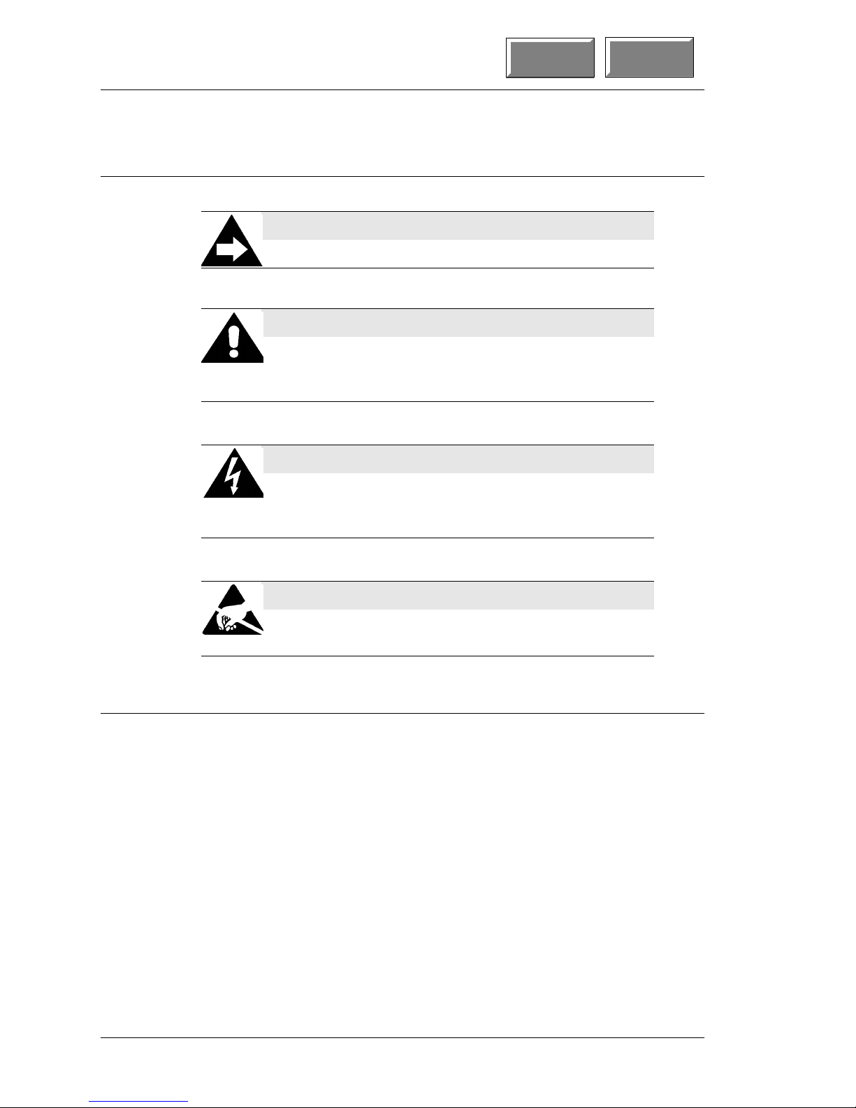
Symbols
NOTE
This symbol brings special attention to a related item.
WARNING
This symbol indicates that specific handling
instructions or procedures are required to prevent
damage to the hardware or loss of data.
SHOCK HAZARD
1st Pa ge
Contents
This symbol calls attention to a potential hazard that
requires correct procedures in order to a void personal
injury.
STATIC SENSITIVE DEVICES
This symbol indicates that specific ESD handling
procedures are required.
Document Design and Production
Desktop Publishing by Adobe FrameMaker 5.1.1.
Illustrations by Corel Draw!™ 7.0, and P aint Shop Pro 4.0,
running under Windows 95
xii
Page 11

The System
Contents
Chapter 1
This chapter provides an introduction to the PCWS Ultra and
accessories, lists care and handling instructions for the
hardware and shows you how to connect the components.
In this chapter
What is the PC Workstation? ...................................................1-2
Care and Handling....................................................................1-8
Connecting the Basic System .................................................1-10
PCWS Ultra Setup Guide 1-1
Page 12

Setup Utility
The PhoneixBIOS Setup Utility provides a central location for
configuring the PCWS Ultra system boar d ha rdw ar e. The BIOS
Setup Utility is stored in a Flash EPROM, so it is avail able even
if a hard disk or operating system is not installed. All settings
are retained in a battery protected CMOS RAM when power is
off.
Contents
Chapter 2
For information on the latest BIOS versions and upgrades, see
the hardware supp ort section o f th e MI C R OS web site at
micros.com.
In this Chapter
Starting the PhoenixBIOS Setup Utility.................................2-2
Main Menu ...................................................... .. .. .. ....................2-4
Advanced Menu.... ............... ................ ............... .......................2-5
Security Menu .........................................................................2-10
Power Menu.............. ................ ............... ............................. ...2-11
Boot Menu................................................................................2-13
Exit Menu ............... ............................. ............... ................ .....2-14
PCWS Ultra Setup Guide 2-1
Page 13

Setup Utility
1st Page Contents
Starting the Phoen ixB IOS Setup Utility
Starting the PhoenixBIOS Setup Utility
Requirements:
A PC Keyboard with a PS/2 style connector.
Procedure:
1. Powe r-up the PCWS
❏ You can power-up, or press the [CTRL]-[ALT]-[DEL] keys at
the same time.
2. Press the [F2] key when prompted.
❏ You should be at the PhoenixBIOS Setup Utility main
screen.
❏ For information on how to navigate around the each menu
and make selections, press [F1] or check the help
information at the bottom of the screen.
❏ There are six primary selections: the start-up menu, Main,
Advanced, Security, Power, Boot, and Exit. An overview of
each selection follows.
Main
This menu lets you set the system date and time, define the
type of floppy and hard disk installed, and displa y s the total
amount of memory installed on the system board.
Advanced
This menu provides access to many Ultra hardware features
including Plug and Play OS settings, IDE and PS/2 Mouse
configuration, PCI slot resource allocation/excl usio n, and IO
device configuration.
Security
From this menu you can enable the security features of the
BIOS, including password entry to enter BIOS setup, and or
boot the workstation.
Power
This menu provides access to the PCWS power saving modes. A
pre-configured power savings mode may be used or the user
may configure a power savings mode manually by defining
several parameters.
2-2
Page 14

1st Page
_
Contents
Starting the PhoenixBIOS Setup Utility
Setup Utility
Boot
This menu allow the user to select the PCWS boot device
priority. The boot device may be External Floppy Diskette Unit,
internal IDE hard disk, ATAPI compatible CD-ROM Drive or
Network Boot ROM.
Keys Used During Setup
Pressing the [F1] key at any time displays a help menu that shows
how to move and around and make selections from each screen.
PCWS Ultra Setup Guide 2-3
Page 15

Setup Utility
Main Menu
Main Menu
The following section describes the Main screen settings and lists the
recommended default where possible .
1st Page Contents
System Time:
System Date:
This pair of fields set the system time and date. Time is entered in
the 24-hour military time format. For example, 1PM is 13:00:00,
6PM is 18:00:00, and so forth. Use the -/+ keys to select a value,
then press enter to advance to the next field.
Legacy Diskette A:
This sub-menu determines if the External Floppy Diskette Unit is
installed. Select “1.44/1.25 Mb 3½” to enable the External Floppy
Diskette. To boot the workstation from a floppy, see the Boot Menu
for more information.
Primary Master
W e recommend you leave this field set to the de fault of “Auto” for all
drives. When you install a hard disk. the BIOS will automatica lly
detect the drive parameters and optimal settings for almost all
modern IDE hard drives. If you do not wish to use the Auto
selection, you may enter the drive parameters manually by
pressing [ENTER] and consulting the item specific help screen.
Refer to the “Installing a Hard Disk” section in Chapter 3.
Keyboard Features
This sub-menu provides access to several keyboard features such as
the power-on state of the num lock key, enabling/disabling a
keyboard “click”, and defines the Auto-repeat rate and delay.
System Memory
Extended Memory
These fields are display only. The size of “System Memory” will
typically be 640K. The size of “ Extende d Memory” is d etermined by
the size of the DIMM installed. The sum of the System Memory and
Extended Memory should equal the size of the DIMM installed on
the system board.
2-4
Page 16
1st Page
Contents
Advanced Menu
This menu provides several sub-menus where you access many of the
Ultra system board hardware features.
Plug & Play O/S
This selection determines if the operating system on the hard disk
supports the Plug and Play specification.
❏ If using Windows 95 or 98, select [Yes].
❏ If using any version of UNIX, or Windows NT Workstation
Version 4.00 select [No].
_
Setup Utility
Advanced Menu
WARNING:
If this field is not set to match the operating system as
described above, you may experience problems with
the on-board AMD Ethernet controller.
Reset Configuration Data
Selecting Yes resets the BIOS Plug and Play configuration data.
This field automatically resets to No after a re-boot.
Secured Setup Configurations
If Yes, prevents a Plug and Play operating system from changing
any system settings.
Local Bus IDE Adapter
This selection enables/disables the system board IDE interface. By
default, this selection is “Enabled” to ensure a hard disk can be
detected automatically when it is installed.
PS/2 Mouse
This selection enables or disables the rear panel PS/2 mouse port.
When set to [AUTO] (default), it is up to the operating system to
detect and use the mouse. [Disabled] disables the PS/2 mouse port
and frees up IRQ12 for other uses.
PCI Device Slot
This selection allows you to designate a PCI card installed in the
Ultra PCI/ISA Riser Card as a Master. Some very old PCI cards
may require this . Consult the documentation supplied with card.
PCWS Ultra Setup Guide 2-5
Page 17

Setup Utility
Advanced Menu
1st Page Contents
PCI/PNP ISA IRQ Resource Exclusion
This sub menu allows you to reserve specific IRQ(s) for use by
legacy devices and indicates if the IRQ has been assigned.
By default, all IRQ lines are set to [Available], which means they
are “available” to the PCI/PNP resource pool. At power up, the
BIOS assigns IRQs from this pool as required to the on-board PCI
devices (VGA controller, network controller, IDE controller, and
USB controller), as well as the system board COM and LPT ports.
If you install a legacy ISA such as a multi-port serial card that
requires one or more interrupts , set those IRQ lines to [Reserved] to
prevent the BIOS from assigning them to PCI devices.
If the message “Indicates a DMA, interrupt, I/O, or memory
resource conflict with another device” appears when you select
[Reserved], that IRQ has been assigned to a device in the pool. If
the message does not appear, it means the IRQ is available.
Once you know what resources are available , set the board jumpers
and set those IRQ lines to [Reserved].
I/O Device Configuration
This sub-menu allows enable/disable and manually configure the
on-board COM and LPT ports, as well as enable the floppy disk
controller.
Serial port A:
This selection configures the rear panel DB9 serial connector.
The Default setting is “Auto” which allows the BIOS to
determine the settings. Select “Disabled” to turn off the port
and use the resources elsewhere. Select “Manual”, to allocate
the resources manually. When you select a Manual
configuration, you must enter the following values.
Base I/O address:
The Base IO Address determines the COM port designation
with three available selections. 3F8 corresponds to COM1,
3E8 corresponds to COM3 and 2E8 corresponds to COM4.
Note: I/O address 2F8 (COM2) is reserved for the
touchscreen controller.
Interrupt
You must assign IRQ3 or IRQ4 to the COM port.
2-6
Page 18

1st Page
_
Contents
Advanced Menu
Setup Utility
Serial LCC Port: (Manual)
This selection configures the multi-function LCC port,
consisting of a rear panel RJ45 connector. Select “Disabled” to
turn off the port and use the resources elsewhere. Select “Auto”
to allow the BIOS to determine the port resources
automatically. When you select “Manual”, the default
configuration, you must enter the following value.
Base I/O address: (COM4)
The Base IO address determines the COM port designation.
Three selections are available. 3F8 corresponds to COM1,
3E8 corresponds to COM3 and 2E8 corresponds to COM4.
COM1 is already assigned to the rear panel DB9 connector
and COM2 is assigned to the touchscreen. The default
setting for this port is 2E8, or COM4.
Interrupt: (IRQ 11)
You must assign IRQ11 to this port.
Mode: (RS422+)
This field selects the operating mode of the port. The
[RS422+] (default, on BIOS release 1.00c or later) and
[RS422-] modes are a reference to sender (+) or receiver (-) o f
information in a MICROS Integrated Device Network (IDN).
The default setting is RS422+ which allows the workstation
to drive IDN devices in applications such as 3400 and 3700.
Selecting the [RS232] mode allows OPOS compatible serial
devices to attached to the workstation.
Parallel Port (Auto)
This selection configures the rear panel parallel port connector.
Select “Disabled” to turn off the port and use the resources
elsewhere. Select “Auto” (default) to allow the BIOS to
determine the port resources. Select “Manual”, to allocate the
resources manually. When you select a Manual configuration,
you must enter the following values.
Base I/O address:
The Base IO address determines the LPT port designation o f
the parallel port. 378 corresponds to LPT1 and 3BC
corresponds to LPT2.
PCWS Ultra Setup Guide 2-7
Interrupt:
You may assign IRQ5 or IRQ7 to the LPT port, if required.
Page 19
Setup Utility
Advanced Menu
1st Page Contents
Mode: (Bi-directional)
This selection defines the parallel port mode. In most cases,
the driver software for any device (a parallel port CD-ROM
drive for example) you install enables the fastest possible
parallel port configuration.
❏ “Output only” selects the Centronics parallel mode
❏ Bi-Directional (default) selects bi-directional mode, also
known as PS/2 mode
❏ “EPP” selects the Enhanced Parallel Port mode
❏ “ECP” selects the Extended Capabilities Parallel Port.
When this mode is selected, you must define a DMA
channel. Press enter to see a list of DMA c hannels. DMA
channels 1 or 3 are recommended.
Floppy disk controller (Enabled)
This selection enables/or disables the system board floppy
diskette interface. Always leave this set to enabled, then enter
the floppy diskette type in the Main Menu to enable the
external floppy.
Base I/O address:
Leave this selection set to “Primary.”
LCD Contrast
This selection allows the contr ast to be adjusted on passive LCD
panels. Use the -/+ keys to adjust the contrast setting.
Application programs adjust the LCD contrast through the
PCWS Application Programming Interface (API).
Minimum
Maximum
These fixed values correspond to the minimum and
maximum contrast values for a given LCD panel. These
values are determined by the BIOS based on the type of
passive LCD panel installed.
NOTICE:
The LCD contrast setting has no effect on active
matrix LCD panels.
UPS Interrupt Type
This field should be set to [Disabled].
2-8
Page 20

1st Page
_
Contents
Advanced Menu
The following fields are found only on BIOS Version 1.00d or
later.
Setup Utility
Mag Stripe Reader IRQ: (IRQ9)
This selection allows you to assign an IRQ resource to the
internal mag stripe reader. Press [Enter] to view a list of IRQ
lines. IRQ confli ct ch ecking is not implement ed. U se the de faul t
of IRQ 9 if possible.
Mag Stripe Reader Mode: (Special)
This field selects one of two operating modes for the internal
mag stripe reader.
Magtek
When this mode is selected, track 1 and track 2 card data is
converted into standard PC keyboard keystrokes to make it
appear as if the card data was entered on the keyboard.
However, this means that certain card data such as the LRC
(Longitudinal Redundancy Check) character will not be
available to applications that require it such as credit
authorization software.
Special
When this mode is selected, track 1 and 2 mag card data is
left intact and placed in a buffer where it can be accessed
through the PCWS API. This method is used for credit
authorization programs.
PCWS Ultra Setup Guide 2-9
Page 21

Setup Utility
Security Menu
Security Menu
This menu provides access to the security features of the Phoenix
BIOS.
Set User Password
This selection allows you to define a password that is required to
enter the BIOS Setup screens. If you select [Enter], you will be
asked to enter and then confirm a password that will be requir ed to
enter setup.
Password on boot:
This selection, if enabled, and if a pass word has been entered in the
selection above, requires password entry before the workstation
will attempt to boot from the selected boot device.
Fixed disk boot sector
This selection enables/disables write protection for the hard disk
boot sector to serve as basic anti-virus protection.
1st Page Contents
2-10
Page 22

1st Page
Power Menu
This menu provides access to the Ultra System Board power saving
features. These features are disabled in the default settings.
_
Contents
Power Menu
Power Savings:
This field selects the power management mode .
Disabled (Default)
Turns off all power management features. This setting is
recommended for most applications.
Maximum Power Savings
This selection provides the greatest amount of power savings
but may affect sy stem performance. Sets the Auto Suspend
Time-out field to 5 minutes.
Setup Utility
Minimum Performance
This selection conserves less power, but performance is not
affected. When enabled, sets the Auto Suspend Time-out fiel d to
15 minutes. The time-out can be adjusted as described below.
Customized
This selection lets you define a custom Auto Suspend Time-out
value.
Auto Suspend Time-out
User defined time period before power saving mode becomes
active. Default is 15 minutes.
Resume on PCI Bus Activity
This ON/OFF toggle determines if PCI bus activity will “wake-up”
the system from a power savings mode . This enable s PCI device s to
restart the system from Suspend Mode through a specific signal on
the PCI bus.
Resume on time
This selection enables/disables the system to wake up at a specific
time, defined below.
Resume Time
When Resume on time is enabled, enter the specific time to wake
up in this field. 24 hour time entry.
PCWS Ultra Setup Guide 2-11
Page 23

Setup Utility
Power Menu
1st Page Contents
IRQ activity monitoring
This sub-menu allows you to select one or more IRQ resources that
when active, can be used to wake-up the workstation. For example,
in the default configuration, any activity on IRQ3, IRQ4, or IRQ12
will “wake-up” the system.
IRQ3 or IRQ4 are typically assigned to the rear panel DB9 COM
port and touchscreen interface. IRQ12 is typically assigned to the
PS/2 mouse port. Activity on any of these ports will wake up the
workstation from a power-d own mode.
2-12
Page 24

1st Page
Boot Menu
This selection lets you select how the workstation will boot.
_
Contents
Setup Utility
Boot Menu
Boot On-Board LAN
This is the setting for a diskless workstation. When this field is set
to “enabled”, the workstation will power-up looking for a BOOTP
server running Windows NT or SCO UNIX. The default setting is
“Enabled”. When this field is set to enabled, the Boot Device
Priority settings, described below, are ignored.
When set to “Disabled”, the workstation will look to the Boo t Device
Priority settings, described below.
Boot Device Priority
When the workstation powers-up and finishes the P ower-On Self
Test (POST), it attempts to load the operating system. If the Boot
On-Board LAN field described above is disabled, this menu
determines the order of devices which the BIOS will search for the
operating system. This menu will also appear after a Flash BIOS
update. Press [Enter] to view the default list, shown below.
❏ 1. Diskette Drive (if installed)
❏ 2. Hard Drive
❏ 3. ATAPI CD-ROM Drive
❏ 4. Network Boot
In this example, the External Floppy Diskette will be c hec ked fir st,
then the hard disk. However, if a floppy disk is not installed, the
workstation will look for the operating system on the hard disk.
PCWS Ultra Setup Guide 2-13
Page 25

Setup Utility
Exit Menu
Exit Menu
1st Page Contents
This selection allows you to exit the system setup utility while saving
or discarding changes made in the various menus. [F10] saves changes
and exits with two ke y st ro ke s.
Exit Saving Changes
Exit system setup and save changes to CMOS RAM.
Exit Discarding Changes
Exit system setup without saving changes to CMOS RAM.
Load Setup Defaults
Load the setup defaults as shipped from the factory. This selection
can be used to recover from improper settings made in the
Advanced menu.
Discard Changes
Discard any changes you have made this session, but do not exit
setup.
2-14
Page 26
The System
What is the PC Workstation?
What is the PC Workstation?
The MICROS PC Workstations are a family of touchscreen based
personal computers designed expressly to meet the needs of the
food service, hotel and retail industries.
This is because the PCWS extends the PC fea ture set to inc orporate
point-of-sale functionality including such items as an integral mag
card reader, customer display, and cash drawer interfaces among
others. A Software Developers Kit is available that provides the
software and documentation required to leverage these unique
features for third party applications.
Like any personal computer, the PC Workstation is changing to
keep up with advances in processor, memory, and LCD technology.
The Ultra system board represents the latest development.
To continue our description, the MICROS PCWS (PC Workstation)
can be viewed from three dimensions: Profile, Display, and System
Board, detailed in the following pages.
1st Page
Contents
Profile
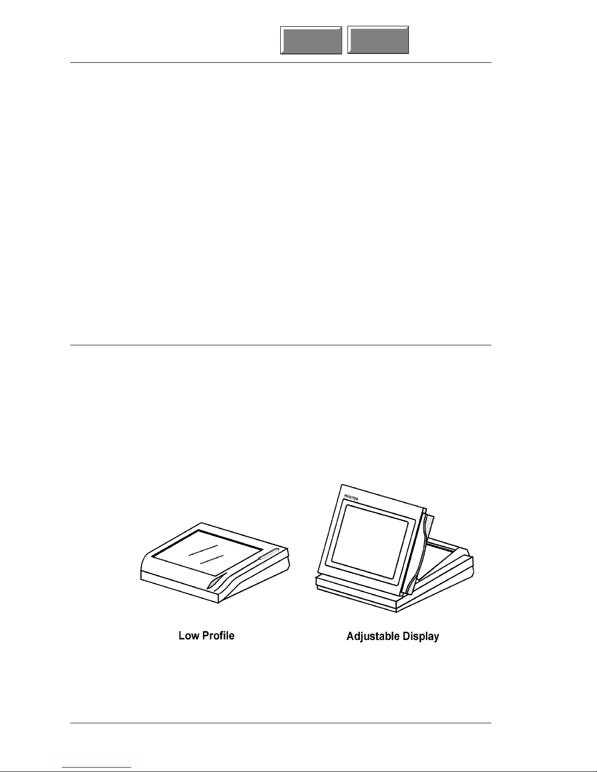
Low Profile and Adjustable Display Case
All PC Workstations are available in a Low Profile (LPs), or
Adjustable Display Sharp (ADs) case style. The AD case can use a
variety of 11.3” and 12.1” active and passive LCD panels. The LP
case does not support 12.1” LCD panels. Figure 1-1 shows an
example of the LPs (left) or ADs (right) casework.
Figure 1-1: The PCWS Low Profile and Adjustable Display
1-2
Page 27

1st Page Contents
Display and Touchscreen
PC Workstations support a variety of backlit active and passive
matrix LCD panels. The display is closely integrated with a highly
reliable, 5-wire t ouchscreen panel which c an replace the t raditional
mouse or other pointing devices.
The AD and LP casework influences the size of the LCD. The Low
Profile case supports only 11.3” LCDs. The AD case supports both
11.3” and 12.1” LCD panels. The Ultra system board adds support
for a 12.1” passive LCD.
Both the LP case, and the Sharp 11.3” passive LCD goes end-of-life
in mid 1999.
System Boards
With the introduction of the Ultra System Board, there are now
four PCWS System Boards in the field. A brief description of each
follows. These system boards can be installed in either the LP or
AD case.
The System
What is the PC Workstation?
Model 32R and 32L
The Model 32R and 32L system boards represent the 486/586
processor class. These system boards set the standards for those
that follow.
Model 64
The Model 64 System Board features the “Classic” Intel P54C
Pentium
features of the Model 32R and 32L System Boards.
®
processor while retaining all of the POS compatible
Ultra
The latest in the series of PC Workstation system boards, the Ultra
brings new flexibility to the PCWS family by supporting the
Pentium
number of active and passive LCD panels.
The Ultra system board is designed to fit into the existing LP and
AD casework without modifications. However, this does not mean
the Ultra system board is a drop-in replace ment for the M64 system
board.
®
MMX and AMD K6 processors, as well as a greater
PCWS Ultra Setup Guide 1-3
Page 28

The System
What is the PC Workstation?
PCWS Accessories
Each PC W o rkstation from the Model 32 through the Ultra uses t he
same basic set of accessories including:
❏ External AC Adapter
❏ External floppy diskette unit (o ptional)
❏ PC Keyboard (optional)
❏ Remote Customer Display (optional)
Details on connecting these devices to the workstation can be found
later in this chapter.
Expansion Capabilities
A half-size PCI or ISA expansion card can be installed if the
optional Ultra PCI/ISA Riser Card is used. This Riser Card is not
compatible with the Riser Card used for the Model 64 system
board.
1st Page
Contents
Diagnostics Utilities
There are two versions of diagnostics utilities designed to test the
POS extensions of the Ultra PC Workstation. The first,
WorkStation Diagnostics Te st (WSDT), is intended for the DOS or
Windows 95/98 command mode environments. Once installed on a
bootable floppy diskette, WSDT forms a complete stand-alone
diagnostics utility, used primarily to confirm basic functionality of
the workstation POS extensions.
The second version, DEMODIAG, runs in the Windows 95/98 and
Windows NT environments . Eac h diagnostics utility all ows you test
the LCD, backlight, mag stripe reader, customer display(s), and
other ports. Please note that neither diagnostics utility is intended
to replace off-the-shelf PC diagnostics utilities that test PC
functions such as memory, hard disk, and the processor.
Both diagnostics utilities are available in the hardware support
section of the MICROS web site, www.micros.com.
PCWS API
The PCWS Application Programming Interface (API) is a set of
services that resides between the application and oper ating system
(Windows 95/98 or Windows NT) and the unique POS hardware on
the system board. This allows the application programmer to use a
standard set of API calls to access such POS features as LCD
contrast, mag stripe data, and the cash drawers.
1-4
Page 29

1st Page Contents
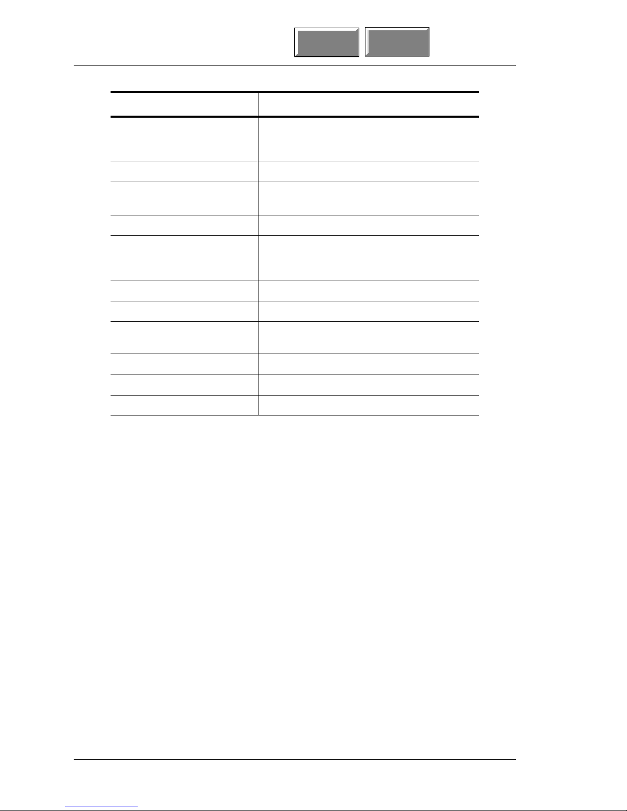
Specifications
Specification Parameters
Processors Intel P54C or P55C
Processor Socket 231-Pin Socket 7 ZIF Socket
Displays 11.3” passive or 12.1” active or passive
Touchscreen Elo five-wire resistive, 100 thousands points-
Backlight(s) Can be set to one three intensity levels by the
VGA Interface On-Board PCI based Chips and Technologies
The System
What is the PC Workstation?
The Ultra conforms to the following specifications.
per-inch resolution, screen life of over 35
million touches
API
65554 graphics accelerator with 1MB EDO
RAM supports VGA, or SVGA standards, and
displays up to 4096 colors on passive LCDs
and up to 16 million colors on active LCDs.
BIOS Plug ‘n Play, DMI 2.0 compliant in flash
EPROM, includes LAN boot software to
support diskless workstations.
BIOS Setup Utility Configures system time and date, floppy and
hard drive parameters, COM and LPT port
resources, and the boot priority device.
Spread Spectrum Bus Clock 60 or 66.8 Mhz, 50 kHz modulation
Real Time Clock Time-of-day clock: 100-year calendar with
alarm features and century roll-over, includes
256 bytes of battery backed CMOS RAM,
reserved for BIOS use.
Memory Single DIMM socket supports from 8 to 128
MB of 60ns EDO or SDRAM
External (L2) Cache 512 Kb on-board, write back PBSRAM
Mag Stripe Reader ABA compatible, operates in MAGTEK and
Special modes.
Customer Displays One-line 20 character display mounts to LP or
AD case, and or two-line 40 character remote
pole mount display
USB Port Two UHCI 1.1 compliant ports
PCWS Ultra Setup Guide 1-5
Page 30
The System
What is the PC Workstation?
Specification Parameters
LAN Interface On-board PCNet AMD AM79C970 PCI based
Parallel Port Supports centronics, EPP, and ECP standards
Riser Card Supports half-size ISA or PCI expansion card
Input Power 50W, max
Input Voltage +24VDC, +25%/-8% (+22VDC to +30VDC)
Input Current 0.21A to 2.1A
Storage Temperature -25°C (-13°F) to 85°C (185°F)
Operating Temperature 5°C (40°F) to 45°C (113°F), 90% relative
1st Page
Ethernet controller, with rear panel 10BaseT
modular connector
and future sound card
from an external AC adapter or future supplied
UPS
humidity max
Contents
Weight 5.5 kg. (12lb), approximately)
Case Material ABS Plastic
Physical Dimensions See Appendix A
1-6
Page 31

1st Page Contents
Approvals
The System
What is the PC Workstation?
The Ultra meets the following safety and environmental
certifications.
Certification Number Comments
Underwriters Laboratory, Inc., Standard for
Safety of Information Technology Equipment
CE European Union Declaration of
Conformity, Electromagnetic Compatibility
Directive
FCC Rules for Class A computing devi ces Part 15
Canadian Standards Association Standard 22.2
Test and Declaration of Conformity for CE
Mark of European Safety Approval
Test and Declaration of Conformity for CE
Mark of European EMI Approval
Test and Declaration of Conformity for CE
Mark of European ESD, RF, and Transient
Susceptibility
International Electrotechnical Commission,
Electromagnetic Compatibility for
Industrial-Process Measurement and Control
Equipment
UL-1950
89/336/EEC
EN60950
EN55022
EN50082-1
IEC801-2 8kV
IEC801-3 27-500MHz, 3V/cm
IEC801-4 0.5kV SIGNAL LINES,
(UNMOD)
1.0kV AC Mains
PCWS Ultra Setup Guide 1-7
Page 32

The System
Care and Handling
Care and Handling
Environmental Requirements
T o ensure proper operation of the equipment, consider the following
guidelines for placement of the PC Workstation.
Dimensional data for each workstation case and accessories can be
found in Appendix A of this manual. Before you decide on the space
each device should occupy, take measurements and compare them
to ours.
Location
Tile is the recommended floor surface for areas surrounding the
workstation. If the floor covering adjacent to the equipment is
carpeted, an anti-static grade is recommended. If the carpeting
surrounding the area containing the equipment is not composed of
anti-static material, the use of static-discharge mats should be
considered. The recommended type of anti-static mat is one that
incorporates a grounding clip with a cable to provide a disch a rge
path to ground.
1st Page
Contents
Foreign Materials
WARNING:
Do not use sharp objects such as a pen or pencil to
press keys on the touchscreen as this could damage t he
sensing layer.
Liquid spillage can cause damage to the circuits in the
unit. Do not place the equi pment near food prep eration
areas, disk racks, or water stations. The PCWS
includes a gasket seal around the touchscreen which
may afford some protection from liquid spillage. Also,
the mag card reader assembly is mounted to a tray
that is designed to prevent liquid spills from reaching
the system board.
If any type of liquid is spilled onto the touchscreen or
mag card reader slot, turn off power as quickly as
possible and remove the spillage. Do not power-up the
unit until it has been determined that no spillage
remains inside the unit.
1-8
Page 33

1st Page Contents
Cleaning
The System
Care and Handling
Electrostatic Discharge (ESD)
The occurrence of electrostatic discharge (ESD) usually takes the
form of a discharge from the operator’s hand to cash drawers, the
workstation, or other peripherals connected to the workstation.
ESD is more common in the dry climates during the winter, and
less common in the moist climates. The PCWS has good built- in
immunity to ESD in most environments. However, tile or anti-static
carpet should still be employed in the area near the workstation.
Temperature and Humidity
The continuous operating temperature for the PCWS is between
40°F and 113°F (5°C to 45°C). A constant humidity between 40%
and 90% is desired for proper operation of the equipment.
WARNING:
Always use a chamois or clean lint-free clo th to clean
the PCWS cabinet and touchscreen surface . Do not use
chemical, alcohol, or petro leum based cleaners that are
not recommended for plas tics.
Depending on how much they are used, floppy drives,
mag card readers and tape backup drives require
periodic cleaning. Cleaning kits are available from a
variety of sources. Be sure to follow the instructions
supplied with the cleaning kits.
Transporting the Workstation
If a hard disk is installed, always power down the workstation
before transporting it, even if you are just moving it across your
work surface. The high density hard drives used today are more
susceptible to damage if subjected to a sudden physical shock while
they are operating, especially if the heads happen to be reading or
writing to the disk surface. Powering off the workstation
automatically parks the heads, allowing you to move the unit
without risking damage to the hard disk.
PCWS Ultra Setup Guide 1-9
Page 34

The System
Connecting the Basic System
Connecting the Basic System
The following pages describe the rear panel conne ctors, then shows
how to connect and configure each external option.
To install or upgrade options within the workstation, refer to
Chapter 3.
Rear Connector Panel
The PCWS Ultra rear connector panel is shown in Figure 1-2,
below.
1st Page
Contents
Figure 1-2: The PCWS Ultra Rear Connector Panel
NOTICE:
This equipment shall only be connected to a public
telecommunications network by an external device
approved for use in the country in which the
equipment is installed.
LCC
This port has several uses depending on the application software.
In the LCC mode with applications that support it, this port
typically drives one or more MICROS Stand-alone IDN Roll and
Slip Printers. In RS232 mode, this port can support a growing
number of RS232 based peripherals such as roll and slip printers,
serial cash drawers, remote customer displays, etc.
Floppy Disk Drive
The External Floppy Diskette Unit is connected to this port. It
contains a high-density 1.44 Mbyte 3 1/2” drive and power supply.
1-10
Page 35

1st Page Contents
Parallel Port
The parallel port is an industry standard Centronics parallel
interface. In addition, the parallel port also supports the EPP and
ECP standards.
RS232 Serial
This industry standard DB9 male connector can be used for an
external modem, or other serial peripheral device. This port is
supported by a 16550 UART with a 16-byte receive buffer.
Power +24VDC
All PC Workstations use the same external AC adapter to provide
+24VDC @ 2.1A to a compact and efficient current mode switching
power supply located on the system board. The PCWS AC power
switch is located on the external AC adapter.
Cash Drawers 1 and 2
These connectors support standard and low profile MICROS cash
drawers with DIN style connectors.
The System
Connecting the Basic System
USB
The Universal Serial Bus (USB) interface supports the host
controller functions with a built-in Root Hub and 2 USB ports. The
USB circuitry is implemented based on OpenHCI, the Open Host.
Display
This connector supports a pole mount Remote Customer Display.
This display contains a two line 20 character alp ha numeric display
that can be mounted up to 6 feet from the workstation.
Ethernet
The Ultra system board includes a PCI based Ethernet controller.
The rear panel connector uses the 10BaseT version of Ethernet.
10BaseT networks are based on inexpensive and easy to install
twisted-pair cabling. See the MICROS Guide to Local Area
Networks, P/N 100038-152, or the 3400/3700 and 8700 Hardware
Site Preperation Guides for more information about 10BaseT
networks.
KYB
This port accepts a PC keyboard with a PS/2 style connector.
Mouse
New to the Ultra system board, this port accepts a standard PS/2
style mouse.
PCWS Ultra Setup Guide 1-11
Page 36

The System
Connecting the Basic System
External AC Adapter
The procedure below outlines how to connect the External AC
Adapter to the PCWS.
The PCWS Ultra does not include an AC power switch. This switch
is located on the external AC adapter.
Procedure:
1. Locate the power ON/OFF switch on the external AC adapter
and make sure it is set to OFF (O).
2. Plug the cable with the DIN connector from the external AC
adapter to the “P o wer +24VDC” c onnector as sho wn in Figur e 1-
3.
3. Connect an AC power cord between the AC adapter and a
properly grounded 3-wire AC outlet.
❏ The power supply is auto-sensing; a jumper is not required
for 230VAC operation.
1st Page
Contents
4. Turn the Power switch to th e ON po si t i on .
Figure 1-3: Connecting th e External AC Adapter
1-12
Page 37

1st Page Contents
PCWS Floppy Diskette Unit
The optional PCWS Floppy Diskette Unit is installed in the
procedure below.
WARNING:
Do not connect the external floppy diskette unit to the
PCWS when power is ON.
The recommended procedure is to alwa ys power -up the
PCWS first, then the external floppy disk drive unit.
When powering down, the recommended procedure is
to power -off external floppy diskette unit first, then
the PCWS.
Procedure:
1. Remove the external floppy diskette and AC power cord from
the shipping container.
The System
Connecting the Basic System
2. Locate the AC power switch on the external AC adapter and
make sure it is set to OFF.
3. Connect the data cable from the floppy diskette unit to the
floppy disk drive connector. Figure 1-4.
❏ Should you need to remove the connector at a later time,
press the tabs on the connector as shown.
4. Connect the external floppy diskette unit to a properly
grounded 3-wire AC outlet.
❏ The power supply is auto-sensing; a jumper is not required
for 230VAC operation.
Figure 1-4: Installing the PCWS Floppy Diskette Unit
PCWS Ultra Setup Guide 1-13
Page 38

The System
Connecting the Basic System
5. Connect a PC keybo a rd w i th a PS/2 style connect o r to the rear
panel if one is not already attached.
6. Power-up the PC Wor kstation.
7. Power-up the external floppy diskette unit.
8. Enter the Setup Utility by pressing [F2] when prompted.
9. From the PhoenixBIOS Setup Utility main screen, scroll down
to the “Legacy Diskette A:” field. Use the - or + keys to select
“1.44/1.25 Mb 3½.””
❏ The External Floppy Diskette Unit is now enabled. If you
wish to boot from the floppy disk, continue with the
procedure below.
10. Use the right arrow key to select the “Boot” menu. Highlight the
“Boot Device Priority” field and press [ENTER].
❏ A list of boot devices appears. The devic e the wo rkst ation
will boot from is [1]. T o boot fr om the external floppy, it must
be moved to the [1] selection as outlined below.
1st Page
Contents
11. Use the up or down arrow keys to select t he devi ce to boot fr om,
then use [-] or [+] keys to move the selection (in this case, the
Diskette Drive) to the 1 position.
12. Press [F10], then [Enter] to save the new configuration and
reboot the workstation.
1-14
Page 39

1st Page Contents
PC Keyboard
The System
Connecting the Basic System
The PC Workstation supports any IBM-PC compatible keyboard
that uses a PS/2 style connector. The following procedure describes
the optional Cherry ML 4100 Keyboard, but in fact applies to any
keyboard equipped with a PS/2 style mini-DIN connector.
CAUTION:
Do not connect or re mo ve th e PC Keyboard when th e
PC Workstation is powered-up.
Procedure:
1. Power-off the PC Workstation.
2. Connect the keyboard PS/2 connecto r to the bottom connector as
shown.
3. Power-up.
4. The system BIOS will automatically detect the keyboard; no
user intervention is required.
❏ However, you may through the Setup Utility, define several
operating para meters for the P C keybo a r d. See Chapter 2
for more information.
PCWS Ultra Setup Guide 1-15
Figure 1-5: Connecting a PC Keyboard
Page 40

The System
Connecting the Basic System
PS/2 Mouse
This procedure shows how to connect a PS/2 style mouse to the
Ultra.
CAUTION:
Do not connect or remove the mouse when power is on.
Procedure:
1. Power-off the PC workstation.
2. Connect the mouse to the connector labeled “mouse” (the top
most connector on the left side of the rear panel).
❏ If left at the factory default setting, the mouse will
automatically be detected by the operating system and does
not require further configuration.
❏ However, if the default setting has been changed, follow the
steps below to enable the mouse port.
1st Page
Contents
3. Power-up the workstation and enter CMOS Setup by pressing
[F2] when prompted.
4. From the PhoenixBIOS Setup Utility main screen, use the right
arrow key to select “Advanced.”
5. From the “Advanced” menu, move down to the “PS/2 Mouse”
field and press [ENTER] to view the selections.
❏ The “Auto” selection allows the BIOS to enable mouse
operation with respect to the operating system. Good ch oice
for DOS users.
❏ The “Enabled” selection allows the operating system to
detect and use the mouse when installed. Recommended for
Windows users.
❏ The “Disabled” setting prevents the mouse from working,
but frees up IRQ12 for other uses.
6. Press [F10] to save the settings and reboot the workstation.
1-16
Page 41

1st Page Contents
Remote Customer Display
The following procedure describes how to assemble and connect the
Remote Cust omer Display to the w or k station.
Procedure:
1. Remove the kit contents from the packing materials.
2. Select the location for the remote display.
❏ Since the hardware required to install the remote display
mounting plate will vary with the thickness and material
used for the counter thus, no hardware is supplied.
3. Use the mounting plate as a template to locate four #14 (.182”/
4.6mm) holes and one 1 1/4” hole.
4. Refer to Figure 1-6 and assemble the remote display.
❏ The inside of one end of the pole is threaded and has two
slots. This end faces the mounting plate.
❏ Loosen the set screw on the p ole to all ow th e displa y head t o
fit inside
❏ Route the cable from the display head through the pole,
mounting plate and nut
❏ Fasten the pole to the mounting plate by lining up the slots
on the pole with those on the mounting plate, then tighten
the nut
The System
Connecting the Basic System
❏ Rotate the display head to the desired location and fasten
the set screw.
CAUTION:
Do not connect or remove the Remote Pole Display
connector when the workstation power is on.
5. Be sure the power to the PCWS is off.
6. Plug the display connector into the customer display connector
on the workstation rear panel.
7. Power-up the PCWS. Setup configuration is not required.
PCWS Ultra Setup Guide 1-17
Page 42

The System
Connecting the Basic System
1st Page
Contents
Figure 1-6: Remote Pole Display Assembly
1-18
Page 43

Contents
PCWS Ultra Hardware
Configuration
This chapter includes a brief description of the Ultra system
board hardware and configuration instructions for the
processor, memory, and hard disk.
Chapter 3
In this chapter
Remove the Cover......................................................................3-2
What’s Inside? ................... ................ ............... ............... ..........3 -4
Processor.......... ... .. ............... ................ ............................ ........3-15
Main Memory ..........................................................................3-21
Hard Disk .. ............................ ................ ............... ...................3-24
Customer Displ ay.......... .. .. ................ ............... .......................3-2 9
LCD Configura t i o n............ .. ............................. ............... ........3-32
Expansion Card Installation ..................................................3-34
PCWS Ultra Setup Guide 3-1
Page 44

PCWS Ultra Hardware Configuration
Remove the Cover
Remove the Cover
Instructions for removing the low profile and adjustable display top
cover are shown on the following pages.
WARNING:
Turn the external AC adapter OFF and remove the
power connector before opening the cover.
PCWS Low Profile
As shipped from the factory, the cover is held in place with two
captive screws.
1. Loosen the two captive screws shown in Figure 3-1.
2. Lift the cover from the unit, setting it to the right as you stand
in front of the unit.
1st Page Content s
Figure 3-1: Removing/Securing the PCWS Low Profile Cover
3. When replacin g th e cove r, secure it with the two screws.
3-2
Page 45

1st Page Contents
PCWS Adjustable Display
The PCWS AD cover is held in place with two screws.
1. Remove the two scre ws fro m the lid ass embl y as s how i n F ig ure
3-2.
2. Lift the lid assembly up from the base and set it to the right as
you stand in front of the workstation.
PCWS Ultra Hardware Configuration
Remove the Co ver
Figure 3-2: Removing/Securing the PCWS AD Cover
3. When reinstalling the cover, if it does not fit securely, be sure
cables are routed properly.
PCWS Ultra Setup Guide 3-3
Page 46

PCWS Ultra Hardware Configuration
What’s Inside?
What’s Inside?
The PCWS Ultra Assembly
Figure 3-3 shows the PCWS Ultra with top cover removed to
illustrate the Ultra system board and inverter board.
1st Page Content s
3-4
Figure 3-3: The PC Workstation Ultra Assembly
Ultra System Board
The Ultra system board is the latest of the line of MICROS PC
W orksta tion system boards . W ith it’s Socket 7 compatible processor
socket, it supports Intel Pentium, Intel Pentium MMX and AMD
K6-2 processors at speeds up to 400MHz. The system board also
includes support for a single DIMM, a new chipset, and a spread
spectrum clock gen e rator to reduce em i ssi o n s. Howev er, the Ultra
system board retains the same form factor, PMW current mode
power supply, touchscreen interface , and LAN interface as the
previous PCWS system boards.
Like all previous PC Workstation system boards, the Ultra reports
its system board type and revision as well as the BIOS software
version at power-up.
Page 47

1st Page Contents
The dimensions of the Ultra system board allows it to be installed
in the existing Low Profile and Adjustable Display casework
without modifications.
Inverter Board
This board includes the DC-to-AC inverter to develop the high
voltage, low current AC for the LCD backlight(s). The system
speaker and local customer display connector now reside on the
Ultra system board. Thus, the inverter/speaker board used on
previous PC Workstations, and the Ultra inverter board are not
interchangeable.
Fan/Air Duct
This assembly consists of a single fan mounted to a sheet metal airduct which fits over the processor and power supply heat sinks . The
rear of the air duct fits in place over top of the existing rear fan
shroud, but a fan is not installed.
PCWS Ultra Hardware Configuration
What’s Inside?
The fan at the front of the air duct draws air in the front of the
workstation and moves it across the processor heat sink and power
supply components.
PCWS Ultra PCI/ISA Riser Card
The Optional Ultra PCI/ISA riser card allows a half-size PCI or ISA
card (but not both) to be installed within the Low Profile or
Adjustable Display case. The Ultra riser card i s not compatible with
the previous Model 64 PCI/ISA riser card.
CMOS Battery
Like any personal computer, the Ultra includes a battery to
maintain CMOS settings and run the real time c lock when power is
off. The Ultra system board uses a CR2032 Lithium battery
mounted in a holder for easy field replacement.
WARNING:
Danger of explosion if battery in incorrectly replaced.
Replace only with the same or equivalent type
recommended by the manufacturer. Dispose of used
batteries according to manufacturer’s or local
requirements.
In the next section, the major system board components are
examined more closely.
PCWS Ultra Setup Guide 3-5
Page 48

PCWS Ultra Hardware Configuration
What’s Inside?
Ultra System Board Components
Figure 3-4 poi nts out som e of the larger dev ices loc ated on th e Ultra
system board. In this view, the air duct, heat sink, and processor
have been removed to expose the underlying components.
1st Page Content s
Figure 3-4: The Ultra System Board Components
Power Supply
To reduce the footprint of the Low Profile or Adjustable Display
workstation, an external AC adapter or “bric k” converts a 110VAC 240VAC input to +24VDC @2.1A.
The Ultra system board includes a compact and reliable PWM
current mode switching power supply that derives all operating
voltages from the +24VDC input.
3-6
Page 49

1st Page Contents
Processor
The Ultra system board includes a “Socket 7” compatible Zer o
Insertion Force (ZIF) socket for the processor. In Figure 3-3, the
processor, processor heat sink, and air duct have been removed to
show the socket.
The Socket 7 architecture provides sup port for all Intel
Classic and P55C MMX Pentium
K6-2, and Cyrix 6x86 processors. The Ultra system board initially
entered production with a Intel Pentium P54C 166 MHz processor.
The processor shipped currently is the Intel Pentium P55C 233
MHz. T e sting and ce rtific ation of AMD K6-2 processo rs is currentl y
under way.
Pipeline Burst Cache
The Ultra system board is currently shipped with 512 kbytes of L2
pipelined burst cache. Pipeline burst cache is composed of a special
type of high-speed static RAM designed to take advantage of the
pipelined architecture of the Pentium processor.
PCWS Ultra Hardware Configuration
What’s Inside?
®
®
Processors as well as the AMD
P54C
Main Memory
The Ultra system board supports a single Dual In Line Memory
Module (DIMM) socket for main memory. A DIMM resembles two
SIMMs placed end-to-end and have replaced SIMMs in a large
number of desktop and tower PCs. Approved DIMMs are listed in
the section on installing memory.
SiS 5581Chipset
The term “chip set” in this case, refers to a single chip, the Silicon
Integrated Systems Corp SiS5581. A short list of functions
includes:
❏ L2 cache controller
❏ DRAM controller for main memory
❏ Host-to-PCI bridge
❏ PCI-to-ISA bridge
❏ PCI IDE Controller
❏ Keyboard Controller
❏ USB Controller
❏ Real Time Clock
❏ Power Management Controller
PCWS Ultra Setup Guide 3-7
Page 50

PCWS Ultra Hardware Configuration
What’s Inside?
System and Video BIOS
The PhoenixBIOS system and video BIOS are integrated into a
single flash device. In addition, the BIOS supports diskless
workstation operation without installing a separate Boot ROM
device.
The PhoenixBIOS incorporates an extensive set of beep codes and
POST error codes, det ailed in Chapter 4.
FPVGA Controller
The Ultra system board includes a Chips and Technologies
C&T65554 Flat Panel VGA Controller. This device is designed for
notebook and laptop computers and therefore supports a wide
variety of active matrix (TFT) and passive matrix (STN) LCD
panels. In addition, the Ultra system board includes two LCD
connectors to increase support for LCD panels .
Video memory consists of a pair of 256K x 16 EDO Page Mode
CMOS Dynamic RAM arranged as 1M x 8.
1st Page Content s
The Ultra system board can use the same 11.3” passive, and 12.1”
active LCD panels as the Model 64. In addition, the Ultra system
board adds support for a 12.1” STN LCD panel installed in the AD
case. LCD panels are configured through a system board DIP
Switch and jumper setting.
Configuration and Control Registers
The Configuration and Control Registers perform the majority of
the Ultra POS related functions. It is composed of U23, a
EPF6016A144 Programmable Logic Device from Altera, a more
advanced version of the AMD MACH part used on previous system
boards. In addition to the programmable IO pins and registers , this
device adds two UARTs.
Touchscreen Controller
The Ultra system board uses the same Elo Graphics Touchscreen
Controller and 5-wire touch panel as the Model 32 and Model 64
workstations. The touchscreen controller communicates to the
system board through COM2.
PCI Ethernet Interface
The Ultra Ethernet interface is based on an AMD 79C970 PCI
based Ethernet controller. The workstation includes a rear panel
10BaseT modular connector.
3-8
Page 51

1st Page Contents
Spread Spectrum Clock Generator
A typical Pentium based system board produces clock pulses with
rise times that result in greater higher-order harmonic energy than
those in previous designs. Spre ad spectrum clocking modulates the
clock signal’s frequency at a 50 KHz rate, spreading the energy of
the clock fundamental to minimize energy peaks at harmonic
frequencies. The clock signal radiates the same amount of energy,
but is spread across a wider range of frequencies without affec ting
the rise and fall times.
Spread spectrum clocking ensures t he Ultra system board will more
readily comply with EMI standards while at the same time greatly
reducing the number of passive components required for EMI
suppression. This, combine d wi th the SiS 5581 core logic device,
reduces number of system board layers from ten to six, increasing
reliability.
Serial/Parallel Ports
PCWS Ultra Hardware Configuration
What’s Inside?
The Ultra system board includes two high-speed serial ports and
one enhanced parallel port. One RS232 Port is based on the
industry standard DB9 connector an d is backed by a 16550 buffer ed
UART.
The second port, also based on the 16550 device, can provide either
an RS422 or RS232 interface via a rear panel 8-pin modular
connector. In RS232 mode, this port supports simple TX/RX
interface lacking hardware hand-shaking support.
In RS422 mode, when used with certain MICROS applications , t his
port is designed to support MICROS IDN devices. The function of
this port is controlled by application soft ware or through the Setup
Utility.
PCWS Ultra Setup Guide 3-9
Page 52

PCWS Ultra Hardware Configuration
What’s Inside?
Ultra System Board Connectors
Figure 3-5 shows all connectors on all revisions of the Ultra system
board. The processor, processor heat sink, and air duct have been
removed.
1st Page Content s
Figure 3-5: PCWS Ultra System Board Connectors
Note the pair of LCD connectors. The 51-pin VESA style connector
may be used for both passive and active matrix LCD panels while
the 41-pin VESA style connector is reserved for passive LCD
panels.
J1, the local customer display connector is now mounted on the
Ultra system board. It was previously mounted on the M32/M64
Inverter/Speaker board.
J12 is a new connector that terminates a ground wire either the LP
cover or the AD pedestal.
3-10
Page 53

1st Page Contents
PCWS Ultra Hardware Configuration
Ultra System Board Jumpers and DIP Switches
Figure 3-6 shows all of the configuration jumper and DIP switch
settings for the Ultra system board.
What’s Inside?
Figure 3-6: Ultra System Board Jumpers and DIP Switches
PCWS Ultra Setup Guide 3-11
Page 54

PCWS Ultra Hardware Configuration
1st Page Content s
What’s Inside?
Ultra System Board Memory Map
The Ultra system board memory map is shown in the Table below.
From To Size Desc ription
0000-0000 0009-FFFF 640Kbytes Conventional Memory
000A-0000 000B-FFFF 128Kbytes Reserved - VGA Display Buffer
000C-0000 000C-FFFF 64Kbytes Reserved - VGA BIOS
000D-0000 000D-FFFF 64Kbytes Available for expansion cards
000E-0000 000F-FFFF 128Kbytes Reserved - System BIOS
0010-0000 07FF-FFFF 127Mbytes Extended Memory (DRAM)
0800-0000 FFFD-FFFF 4 Gigabyte Unused, available for Video
Acceleration Area
FFFC-0000 FFFF-FFFF 256Kbytes System BIOS Ethernet Boot ROM
Figure 3-7: Ultra System Board Memory Map
3-12
Page 55

1st Page Contents
Ultra System Board IO Port Map
IO Address Device/Location Description
0000-000F SiS5581 (U31) DMA Controller 1 (8-bit)
0020-0021 SiS5581 (U31) Interrupt Controller 1
0040-0043 SiS5581 (U31) Timer Control Registers
0060, 0064 M513X (U22) Keyboard/Mouse Data Port
0061 Sis5581 (U31) 8255 Port B
0064 M513X (U22) Keyboard/Mouse Status Port
0070-0071 SiS5581 (U31) RTC/CMOS Registers
0080-008F SiS5581 (U31) DMA Page Registers
PCWS Ultra Hardware Configuration
What’s Inside?
00A0-00A1 SiS5581 (U31) Interrupt Controller 2
00C0-00DF SiS5581 (U31) DMA Controller 2 (16-bit)
00F0-00FF Processor (STK1 ) Numeric Co-process or
01F0-01F7 SiS5581 (U31) IDE Interface
0278-027A EPF6016 (U23) Customer Display (LPT2)
02E8-02EF M513X (U23) LCC COM Port
02F8-02FF EPF6016 / 16450 Touchscreen Port COM2
0330-033F EPF6016 (U23) Config/Status DIP Switch S1
0340-0345 EPF6016 (U23) Mag Stripe Reader Registers
0378-037F M513X (U2 2) LPT 1
03B0-03BF 65554 (GU4) VGA Controller (Mono)
03C0-03CF 65554 (GU4) VGA Controller (EGA/VGA)
03D0-03DF 65554 (GU4) VGA Controller (CGA)
03E8-03EF M513X (U22) Super IO
03F0-03F7 M513X (U22) Floppy Disk Controller
03F8-03FF M513X (U22) Comm Port 1
0CF8-0CFC SiS5581 (U31) PCI Host Bridge Config Registers
Figure 3-8: Ultra System Board IO Port Addresses
PCWS Ultra Setup Guide 3-13
Page 56

PCWS Ultra Hardware Configuration
What’s Inside?
Ultra System Board IRQ Assignments
The table below shows the default IRQ assignments on the Ultra
system board.
IRQ Description
NMI IO Channel Check
0 Reserved - System Interval Timer
1 Reserved - Keyboard
2 Reserved - Cascade from IRQ 9
3 Reserved - Touchscreen Controller (COM2)
4 Reserved - Rear Panel DB9 connector (COM1)
5 Available 6 Reserved - Floppy Diskette
1st Page Content s
7 Reserved - Parallel Port (LPT1)
8 Reserved - Real Time Clock
9 Reserved - Mag Stripe Interface
10 Reserved - Ethernet Controller, USB Port (PCI)
11 Reserved - LCC Port (COM4)
12 Reserved - PS/2 Mouse Port.
13 Reserved - Processor FPU
14 Reserved - Primary IDE Controller
15 Available -
Figure 3-9: Ultra System Board IRQ Assignments
The chart above shows IRQ2, IRQ3, IRQ7, as reserved. However
these ports can be disabled in the I/O Device Configuration Subscreen in the Advanced Setup Utility, freeing these IRQ lines for
other purposes.
IRQ12 is another example. Due to the touc hscreen, t he workstation
in many situations does not require a mouse, You can disable the
mouse port and make IRQ12 available for your expansion card.
3-14
Page 57

1st Page Contents
Processor
PCWS Ultra Hardware Configuration
Processor
The PCWS Ultra system board currently supports the Intel Classic
Pentium
speeds up to 233 MHz. Support has now been added for AMD K6-2/
300 and K6-2/400.
®
(P54C) and Pentium with MMX Processors (P55C) at
WARNING
Never operate the Ultra system board without the
processor heatsink and air duct/fan assembly install ed
and the fan operating.
STATIC SENSITIVE DEVICES
Follow ESD Procedures when replacing or upgrading
the processor.
Processor Configuration Jumpers
Intel and AMD processors utilize a fractional bus operation where
the incoming bus frequency is multiplied to set the processor core
operating frequency. This allows the processor core to operate at
higher frequency while communicating to the system bus running
at a lower frequency.
JP6 sets the bus multiplier input to the processor and JP4
determines the processor supply voltage. For example, the P54C
“classic” Pentium processor requires a supply voltage of +3.54V,
while the Pentium MMX requires +2.84V. Note the alternative
setting for the AMD K6-2/233MHz through K6-2/366MHz. The
alternate setting may be required f or stable operati on due to power
supply tolerances.
JP4 presents a 5-bit binary input to a programmable voltage
regulator, known as the VCORE regulator.
Settings for JP4 and JP6 can be found in Figure 3-16.
AMD Processor Note:
To fully support the AMD K6-2 processors, BIOS
Version 1.00d or later is required. BIOS versions prior
to 1.00d will report an AMD K5 processor is installed,
and does not report the operating speed.
PCWS Ultra Setup Guide 3-15
Page 58

PCWS Ultra Hardware Configuration
Processor
Processor Heat Sink and Air Duct Assembly
The processor is mounted in a 321-pin Zero Insertion Force (ZIF)
Socket 7 compatible socket. The processor heat sink assembly
consists of the heat sink itself, the clip which fastens it to the
processor socket, and a thermal pad between the heat sink and
processor.
The fan is mounted to sheet metal which is formed into a threesided air-duc t or channel. The air duct is attached to the processor
heat sink and fits over the power supply heatsink, and rear fan
shroud. The heatsink is attached to the processor socket by a clip,
with a hinge at one end. A thermal pad is mounted to the bottom of
the heat sink. Heat sink compound is currently not used.
The fan pulls fresh air in through the gap between the base and the
lid, moves it across the processor heat sink, through the air duct,
and out through a shroud at the rear of the base. The shroud is the
same as used in previous workstations, but a fan is not installed.
1st Page Content s
A side view of this arrangement is shown in Figure 3-10, below.
Figure 3-10: The Processor Heat Sink and Air Duct (side view)
If you must replace or upgrade the processor, we recommend that
you do not remove the air duct from the heatsink. It is possible t hat
the air duct will be deformed, and will not fit properly when
reinstalled.
The following procedure describes how to remove and replace the
heat sink and air duct as single unit.
3-16
Page 59

1st Page Contents
Remove and Replace the Processor
1. Remove AC Power from the workstation.
2. Remove the LP or AD cover.
3. Remove the hard disk and bracket, if installed.
4. Remove the fan power cable from J5 as shown in Figure 3-11.
PCWS Ultra Hardware Configuration
Processor
Figure 3-11: Remove the Fan Power Cable
5. Remove the heat sink clip. Refer to Figure 3-12. Press down on
the hinged end to release the clip from the socket.
Figure 3-12: Releasing the Heat Sink Clip
PCWS Ultra Setup Guide 3-17
Page 60

PCWS Ultra Hardware Configuration
Processor
6. Lift the heat sink/air duct up and out. Figure 3-13.
Figure 3-13: Removing the Air Duct and Heat Sink
7. T o remove the pro cesso r from t he soc ket, pull the s oc ket r elease
handle outward, then upward to rotate it to its fully vertical
position as shown in Figure 3-14A.
8. Lift the processor out of the ZIF socket.
1st Page Content s
9. To install a replacement/upgrade processor, make sure the
release lever is in the fully vertical position. Orient the pin-1
indicator as shown in Figure 3-14B, and carefully insert its pins
into the socket.
10. Rotate the release lever to its fully closed position.
Figure 3-14: Remove/Re place the Processor
3-18
Page 61

1st Page Contents
11. Re-install the heat sink/air duct. Figure 3-15.
❏ Fit the assembly into place. The rear of the air duct should
fit over the power supply heat sink and the plastic shroud at
the rear of the base.
❏ Hook the clip to the front of the sock et. Then press down on
the hinged end of the clamp while at the same time hooking
the clamp to the socket,
PCWS Ultra Hardware Configuration
Processor
Figure 3-15: Re-installing the Heat Sink/Air Duct Assembly
12. Reconnect the fan power cable connector to J5 on the system
board.
13. If you upgraded the processor, refer to Figure 3-16 and set JP4
and JP6 to match the processor type and speed.
NOTE:
The markings on current Ultra system boards do not
have the correct voltage settings for all AMD K6-2
processor speed settings.
14. Replace the hard disk.
15. Replace the cover.
PCWS Ultra Setup Guide 3-19
Page 62

PCWS Ultra Hardware Configuration
Processor
1st Page Content s
Figure 3-16: Jumper Settings for Intel and AMD Processors
3-20
Page 63

1st Page Contents
Main Memory
The PCWS Ultra system board main memory consists of single
Dual-In-Line-Memory-Module (DIMM) socket. A DIMM is roughly
the same as a pair of SIMMs connected end-to-end. DIMMs have
been replacing SIMMs in most desktop and tower PCs in the last
few years, and therefore have become inexpensive and readily
available.
The table below shows the available configurations. The Ultra
BIOS and chip set will automatically detect and size the DIMM.
PCWS Ultra Hardware Configuration
Main Memory
DIMM Type Memory
1M x 64 8MB
2M x 64 16MB
4M x 64 32MB
8M x 64 64 MB
16M x 64 128MB
The Ultra system board is designed to use 168-pin, +3.3V,
unbuffered 100MHz Synchronous DRAM (SDRAM) DIMMs. Like
the SIMMs used on the M32 and M64 system boards, the DIMM
must be less than 1 inch in height. Standard PC100 SDRAMs are
taller than 1 inch, preventing the top cover from installing pro perly.
The table below shows the DIMMs currently approved for use in
the Ultra system board. These are devices are custom made for the
PCWS to ensu re a pr o pe r fit.
Size Mfg P/N MICROS P/N
16MB
16MB
32MB
64MB
PNY - 89000193 700502-150
Samsung KMM366S203BTL- 60 700502-150
PNY - 89000214 700502-151
PNY - 89000215 700502-152
PCWS Ultra Setup Guide 3-21
128MB
PNY - 89000247 700502-157
Page 64

PCWS Ultra Hardware Configuration
Main Memory
STATIC SENSITIVE DEVICES
Follow ESD procedures when handling DIMMs.
DIMM Orientation
Figure 3-17, below, shows a DIMM designed for the Ultra system
board. Note that the individual memory chips on the DIMM are
installed horizontally to keep the overall height of the DIMM to less
than 1 inch. The illustrat ion also point s out th e notches that denote
its operating voltage and other parameters.
1st Page Content s
Figure 3-17: DIMM Orientation
DIMM Installation
1. Power off and remove the workstation cover.
❏ If you must remove a DIMM, see Figure 3-19, on the next
page.
2. Line up the notches in the DIMM to match the socket, then
insert the DIMM in the socket. The end clips will snap into
place.
Figure 3-18: Installing a DIMM
3-22
Page 65

1st Page Contents
Removing a DIMM
1. If you need to remove a DIMM already installed, Refer to Figure
3-19, below and gently release the clips on each side of the
socket. Lift the DIMM out.
PCWS Ultra Hardware Configuration
Main Memory
Figure 3-19: Removing a DIMM
PCWS Ultra Setup Guide 3-23
Page 66

PCWS Ultra Hardware Configuration
Hard Disk
Hard Disk
The PCWS Ultra supports a single E-IDE hard disk installed within
the LPs or ADs case.
STATIC SENSITIVE DEVICES
Follow ESD procedures when handling the hard disk.
Requirements
❏ PCWS Hard Drive Kit, available with or without Windows 95 or
Windows NT pre-loaded.
❏ PC Compatible keyboard
❏ PCWS Floppy Diskette.
Procedure:
1. Carefully remove the hard disk and mounting bracket from it’s
packing material.
1st Page Content s
2. If you are installing a hard drive kit from MICROS, you can
skip this step. Otherwise, check the drive select jumpers.
❏
All IDE drives include a set of jumpers that designate one of
several configurations including “master”, “slave”, “single”,
or “cable select”. The master, slave, or cable select settings
are required when two drives share a common interface
cable.
In a single drive installation such as the PCWS, this jumper
must be set to “single”. When you purchase a new drive from
MICROS or elsewhere, this is the default setting.
However, should you “borrow” a hard disk from a desktop
PC with two hard drives installed, one drive will be
configured as a “master” and the other as a “slave”. In some
cases, the cable select function may be used. None of these
settings will function in the PCWS. Consult the
documentation supplied with the hard drive for the jumper
settings of a single hard drive installation.
3. Power off and remove the LPs or ADs cover.
4. If you are not installing a kit from MICROS, make sure you are
using the correct hard disk bracket. Figure 3-20.
3-24
Page 67

1st Page Contents
❏ Note the cutouts in the bracket. They leave room for system
board components. In addition, a new bracket with a
thumbscrew is now being shipped. This bracket is
compatible with all system boards, but only the Ultra
system board can use the thumbscrew because there is a
matching boss on the sheet metal bracket.
PCWS Ultra Hardware Configuration
Hard Disk
5. Mount the drive in the bracket as shown in Figure 3-21.
PCWS Ultra Setup Guide 3-25
Figure 3-20: The Hard Disk Bracket
❏ Attach the power and data cables to the drive as shown.
❏ Connect the power cable to J2 and the data cable to J3 on
the system board.
WARNING:
Exercise care when installing J2. Figure 3-21. While
this connector is keyed, it is possible to force it on
backwards. Be sure to orient the connector as shown.
Damage to the hard disk and or the system board
could result from an improper connection.
Page 68

PCWS Ultra Hardware Configuration
Hard Disk
1st Page Content s
Figure 3-21: Assembling the hard disk bracket
6. Refer to Figure 3-22 and install the drive assembly. For clarity,
the drive itself is not shown.
3-26
Page 69

1st Page Contents
❏ Slide the bracket in from the rear until the front slots line
up with the slots in the base. Then snap the rear clamps in
place outside of the slots as shown.
PCWS Ultra Hardware Configuration
Hard Disk
Figure 3-22: Mounting the Drive Assembly
❏ Twist the thumbscrew clockwise to fasten the hard disk
bracket to the system board.
7. Replace the cover, power-up, and enter the Setup Utility.
❏ The Phoenix BIOS will automatically detect and size the
hard disk.
❏ If the BIOS does not detect the hard disk, re-check the
installation of the cables and the drive select jumpers as
described in Step 2. If the hard d isk cannot be de tected, Ste p
8.
8. Manually configure the hard disk. This step is necessary only if
the hard disk was not automatically detected at power-up.
9. Power up the PCWS and enter Setup by pressing [F2] when
prompted.
❏ The Phoenix BIOS Main screen should be displayed.
❏ Move to the “Primary Master” field, and press [ENTER].
PCWS Ultra Setup Guide 3-27
Page 70

PCWS Ultra Hardware Configuration
Hard Disk
❏ Enter the values for the number of cylinders, heads, and
bytes per sector. This information should appear on a label
on the hard disk case.
❏ Press [F10], then [Enter] to save the new configura tion and
reboot the workstation.
❏ If the workstation still fails to detect the hard disk, try a
new data cable.
1st Page Content s
3-28
Page 71

1st Page Contents
Customer Display
Both the Low Profile and Adjustable Display case styles support an
optional Customer Display that mounts directly to the rear of the
workstation. The LP version consists of a display board and
housing, assembled and ready to attach to the rear of the
workstation base. The AD version consists of the display board only,
which mounts to the AD support bracket at the rear of the base.
LP Procedure:
1. Power-off the workstation, remove all cables from the rear
connector panel, then remove the cover.
2. Remove the shipping materials from the customer display.
3. Refer to Figure 3-23 and attach the customer display assembly
to the case at the points shown.
❏ Route the cable through the slot on the PCWS case, behind
PCWS Ultra Hardware Configuration
Customer Display
the rear fan shroud, then connect it to J1 on the system
board.
Figure 3-23: Attaching the Customer Display (Low Profile Case)
4. Power-up the workstation.
5. The Customer Display is ready to run.
PCWS Ultra Setup Guide 3-29
Page 72

PCWS Ultra Hardware Configuration
Customer Display
AD Procedure:
1. Refer to Figure 3-24 and remove the screws that hold the cover
in place.
1st Page Content s
Figure 3-24: Removing the PCWS AD Cover
2. Lift the cover up and set it to the right side.
3. Remove the Customer Display assembly and cable from its
shipping container.
4. Orient the base so that the AD support bracket on the rear of
the unit is visible.
3-30
Page 73

1st Page Contents
5. Orient the board so that the display is facing you and the cable
is on the right. Refer to Figure 3-25, and hook the two holes at
the top of the displa y board to the mounting tab s on the bracket,
then rotate the display in place.
PCWS Ultra Hardware Configuration
Customer Display
Figure 3-25: Mounting the Customer Display Board
6. Route the cable through the slot in the base, behind the shroud,
and connect it to J2 on the system board.
7. Replace the AD cover.
8. Power-up.
PCWS Ultra Setup Guide 3-31
Page 74

PCWS Ultra Hardware Configuration
LCD Configuration
LCD Configuration
Currently, the Ultra system board supports three LCD
configurations.
❏ Sharp 11.3” (640x480) Passive
❏ Sharp 12.1” (800x600) Passive*
❏ Sharp 12.1” (800x600) Active
* Standard display configuration
Note that the Low Profile (LPs) case supports only 11.3” LCDs. The
Adjustable Display Sharp (ADs) case can accommodate any of the
LCDs listed above. Per PMA99-565, the LP case went end-of-life in
mid 1999.
The LCD type is selected through DIP switch S1. The operating
voltage of the LCD panel (+3.3V or +5V) is determined by GJP2.
Settings for current LCD configurations can be found in Figure 3-
27.
1st Page Content s
The Ultra system board is accompanied by a new backlight inverter
board, shown in Figure 3-26, below.
Figure 3-26: Ultra Backlight Inverter Board
This board contains the backli ght inverter circuit only. In Model 32
and Model 64 workstations, this board also hosted the system
speaker and the connector for the rear mounted customer display.
These items now reside on the Ultra system board.
3-32
Page 75

1st Page Contents
PCWS Ultra Hardware Configuration
LCD Configuration
Figure 3-27: LCD Configuration Jumpers and DIP Switches
PCWS Ultra Setup Guide 3-33
Page 76

PCWS Ultra Hardware Configuration
Expansion Card Installation
Expansion Card Installation
This section provides an overview of Plug and Play, describes the
Ultra PCI/ISA Riser Card, and provides instructi ons for installing a
PCI or ISA expansion card.
Plug and Play
The following information is not intended to repeat the details of
the Plug and Play specification, but merely to pr ovide an overview
of its operational concepts and how they affect you, the installer
adding peripheral ca rds to the PC workst ation . It a lso import ant t o
note that at the time this Setup Guide was written, true Plug and
Play compatibility was available only on the Windows
operating system.
Plug and Play (PNP) is aimed at one of the shortcomings of the
open and extensible architecture of the AT class personal
computers: management and allocation of system resources such as
IO Ports, interrupt requests lines, DMA requests lines, etc. These
resources are in limited supply but are required for almost all
peripheral add on cards. As more add-on cards are added to the AT
bus, the possibility of device conflicts increases because in most
cases, these resources cannot be shared.
1st Page Content s
®
95 or 98
Although the pool of resources is finite, it is still quite extensive.
This is why it makes sense to manage them more efficie ntly than to
simply add more. In fact, the Peripheral Component Interconnect
(PCI) bus represents a step towards better management of
resources at the BIOS and chipset level, but does not include the
operating system. The PCI bus maintains its own set of internal
interrupts associated with each PCI card or system board device . T o
manage these resources, they are combined and placed in a PCI/
PNP “resource pool” where they can be assigned as needed to PCI
or Plug and Play devices.
Legacy ISA Card
The term Legacy ISA card is used to denote older ISA bus cards
that do not conform to PNP specifications. To install these cards,
the technician must know the resource requirements of the card as
well as what resources are available. Configuration of these cards is
typically performed by setting DIP switches to decode IO port
addresses and or setting jumpers to steer IRQ and DMA request
lines to the proper bus pins. Legacy ISA cards may also be
configured by a softw are utili ty. Still , the in staller must kno w what
resources are available and enter them into the configuration
software.
3-34
Page 77

1st Page Contents
Plug and Play spreads the burden of resource management
between the BIOS and chip set, the operating system, and the
manufacturer of the add-in card or chip.
With PNP, the installer simply plugs in the card, turns on the PC,
and lets the BIOS, chipset, and operating system determine the
resource requirements, then assign them.
Thus, the PNP compatible BIOS assumes the role of resource
manager. It is responsible for configuring PNP cards and system
board devices during the Power On Self Test. Once the POST is
complete, and the operating system starts up, it becomes
responsible for managing PNP devices with the BIOS providing
run-time services for the operating system.
Ultra PCI/ISA Riser Card
You can install a half-size PCI or ISA expansion card in the Ultra
workstation by using the optional Ultra PCI/ISA Riser Card. See
the illustration below.
PCWS Ultra Hardware Configuration
Expansion Card Installation
PCWS Ultra Setup Guide 3-35
Figure 3-28: The Ultra PCI/ISA Riser Card
NOTE:
The Ultra PCI/ISA Riser Card is not compatible with
the Model 64 PCI/ISA Riser Card.
Page 78

PCWS Ultra Hardware Configuration
Expansion Card Installation
Installing Expansion Cards in the Ultra PCI/ISA Riser Card
The following procedure describes how to install a PCI or ISA
expansion card in the Ultra PCI/ISA Riser Card. The procedur e
consists of three steps: Installing the expansion card, install ing the
PCI/ISA Riser Card in the workstation, and using the Setup Utility
to configure the add-on card if required.
Procedure:
1. Remove all cables from the rear connector panel, then remove
the cover.
2. From inside the unit, remove the red plastic bracket covering
the rear card slot.
3. Install an ISA card in the Riser Card.
❏ If you are installing a legacy ISA card, select a non-
conflicting IRQ (if required) resource and set the jumpers
❏ Install the ISA card in the socket with the solder side up as
shown in Figure 3-29
1st Page Content s
❏ Secure the ISA card bracket to the riser card bracket with a
screw as shown in the illustration
❏ Proceed to the section entitled “Installing the Riser Card in
the System Board.”
Figure 3-29: Installing an ISA Card
4. Install a PCI card in the Ultra PCI/ISA riser card.
❏ Jumper settings are not required for a PCI card
❏ Install the PCI card with the component facing up as shown
in Figure 3-30
❏ Secure the PCI card bracket to the riser card bracket
3-36
Page 79

1st Page Contents
❏ Proceed to the section entitled “Installing the Riser Card in
the System Board”.
PCWS Ultra Hardware Configuration
Expansion Card Installation
Figure 3-30: Installing a PCI Card
Installing the Riser Card in the System Board
After installing the expansion card, follow the procedure below to
install the Ultra PCI/ISA Riser Card in t he dedi cate d system boar d
connector .
1. Insert the riser card bracket rear tab under the plastic cutout in
the base as shown in Figure 3-31
Figure 3-31: Installing the PCI/ISA Riser Card
PCWS Ultra Setup Guide 3-37
Page 80

PCWS Ultra Hardware Configuration
Expansion Card Installation
❏ Install the PCI/ISA riser card in socket J37, along the left
side of the unit. It should slide most of the way into the
connector. When you feel some resistance, re-check the
alignment at each end of the soc ket , and pr ess firmly t o seat
the board in the socket.
2. From the rear of the unit, install a screw as shown in Figure 332 to secure the Riser Card to the chass is.
1st Page Content s
Figure 3-32: Securing the Riser Card
3. Replace the workstation top cover.
4. Reconnect all external cables. Check the headings below to
configure the device in CMOS Setup.
5. Connect a PC Keyboard to the workstation if one is not already.
6. Proceed to “System Configuration”, below.
3-38
Page 81

1st Page Contents
Expansion Board Configuration
Depending on the type of card you installed, you may have to enter
the Setup Utility and configure it.
Legacy ISA Card
If you installed a legacy ISA card, for each IRQ line it requires,
you must reserve an IRQ in the “PNP/PCI IRQ Resource Pool
Exclusion” screen of the Setup Utility.
The primary question when installing a legacy ISA card is
“what IRQs are available for use with this card?” One way to
find out is to change each IRQ from [Available] to [Reserved] in
the IRQ Resource Pool Exclusion scree n. The BIOS will report if
the IRQ has been assigned to a PCI/PNP device and is not
available for a legacy ISA card. If you are running Windows
95, 98, or NT, you can also see the IRQ assignments through the
control panel.
By default, IRQ3, IRQ4, and IRQ7 are assigned to the system
board COM and LPT Ports. IRQ10 is assigned to the AMD
Ethernet controller. IRQ12 is assigned to the PS/2 Mouse.
IRQ14 is assigned to the primary IDE channel. Otherwise, the
remaining IRQ lines should be available for the legacy ISA card.
PCWS Ultra Hardware Configuration
Expansion Card Installation
®
Should you need to remove an IRQ line from the PnP/PCI
resource pool, proceed as described below.
❏ Power-up the workstation and enter the Setup Utility by
pressing [F2] when prompted
❏ Use the right cursor key to select the Advanced Menu
❏ Cursor down to the “PCI/PnP ISA IRQ Resource Exclusion”
field and press [Enter]
By default, all IRQ resources are made “available” to the
PNP/PCI resource pool
❏ Cursor down to the IRQ line you wish to reserve for the
legacy ISA card and press the [-] key to select [Reserved]
If the message “Indicates a DMA, interrupt, I/O, or memory
resource conflict with another device” appears when you
attempt to reserve an IRQ, it means the IRQ line has been
assigned to a PnP or PCI device by the BIOS. Try another
IRQ line.
PCWS Ultra Setup Guide 3-39
Page 82

PCWS Ultra Hardware Configuration
Expansion Card Installation
ISA PNP Card
If you installed a PNP compliant ISA card such as a modem, no
further configuration is necessary.
PCI Card
If you installed PCI based expansion card, no further
configuration is required unless the documentation states that
PCI card must be designated as a “Master”. If the PCI card
requires this:
❏ Power-up the workstation and enter the Setup Utility by
pressing [F2] when prompted
❏ Use the cursor keys to select the Adv anced Menu
❏ Cursor down to th e “P C I D e vice Sl o t” and press [Ent e r]
❏ Press the [-] key once to select [Enabled]
❏ Press [F10], then [Enter] to save the c hanges to CMOS RAM
and re-boot the workstation.
1st Page Content s
3-40
Page 83

Contents
PCWS Ultra Diagnostics
Chapter 4
This chapter includes diagnostics information on the Ultra
system board.
In this chapter
Basic Troubleshooting...............................................................4-2
Diagnostics LE D s. ............................. ............... ............... ..........4 -4
POST Error Messages...............................................................4-6
PCWS Ultra Setup Guide 4-1
Page 84

PCWS Ultra Diagnostics
Basic Troubleshooting
Basic Troubleshooting
This section provides a brief troubleshooti ng chart for the PCWS Ultra .
Problem Possible Cause Solution
1st Page Contents
PCWS is dead. LCD
is blank, LCD
backlight is off,
fan(s) not running
System Boots from
Floppy Diskette.
Does not boot from
or read from hard
disk.
No Power to PCWS Check AC power
switch on AC
adapter. Make sure
cable from AC
outlet to the AC
adapter and cable
from AC adapter to
PCWS is secure.
Bad power or data
cable to hard disk.
Disk parameters
lost in CMOS Setup.
Boot Priority not
set correctly.
See Chapter 3 and
check the
connections to the
hard disk.
Restarting should
restore hard disk
parameters.
Check Boot Priority
setting in Setup
Utility (Chapter 2)
System Boots from
Floppy Diskette.
Does not boot from
hard disk, but you
can read hard disk
directories and
access data files
System Boots from
Hard Disk. Does not
boot from Floppy
Diskette.
4-2
Hard disk boot
sector lost
No Power to Floppy
Diskette. Cable not
connected.
Floppy Diskette not
enabled in Setup
Utility
Backup all files
and reformat drive.
Restore all files
Check power and
data cable to
Floppy Diskette.
Set Legacy Diskette
A: to “[1.44/1.25
Mb 3½]”
Page 85

1st Page Contents
Problem Possible Cause Solution
PCWS Ultra Diagnostics
Basic Troubleshooting
The LCD is too
light or dark
PS/2 Mouse
installed but not
detected.
LCD Contrast not
adjusted
PS/2 Mouse port not
enabled.
PS/2 Mouse not
fully connected or
connected to
keyboard port.
Defective mouse
Run one of the
contrast adjustment
utilities or use
the “IO Device
Configuration sunmenu” to change LCD
contrast.
Set “PS/2 Mouse”
field in Advanced
menu to [AUTO],
reboot.
Check the mouse
connection to make
sure it is secure.
Mouse connector is
above keyboard
connector.
Replace the mouse
PCWS Ultra Setup Guide 4-3
Page 86

PCWS Ultra Diagnostics
Diagnostics LEDs
Diagnostics LEDs
The Ultra System Board contains several LEDs, used to indic ate
various conditions about the system board. The location of each LED is
shown in the illustration below.
1st Page Contents
4-4
Figure 4-1: Ultra System Board Diagnostics LEDs
When DS1 is ON , this is an in dication t hat the Over Voltage Protection
(OVP) circuit has shut down the on-board power supply.
❏ This condition occurs should the +5V output become shorted to a
higher voltage such as +12V. This could be the result of a
component failure in the power supply, or through a foreign object/
spillage on the system board.
D12, D13, D16 and D17 are part of the 10BaseT interface and have the
following functions.
❏ D17 is active when the interface is transmitting data.
❏ D12 is active if the cable transmit and receive polarity is reversed.
The polarity check function is active after a reset or Link Fail. See
the explanation for D13. The controller has the ability to inver t the
polarity of the signal appearing on the RXD+/- pair if the polarity of
the received signal should be reversed due to an improperly wired
connector.
Page 87

1st Page Contents
❏ D16 is active when the interface is receiving data.
❏ D13 is active when the interface has a good link status.
When the transmit pair is inactive, “link beat pulses” are
periodically sent over the twisted pair cable by all devices to
monitor cable integrity.
The absence of link beat pulses and receive data on the RXD+/- pair
will cause the controller to enter the link fail state and illuminate
D13. While in the link fail state, all data transmission, reception,
loopback and collision detection fun ctions are disabled and will
remain so until valid data or more the 5 consecutive link beat
pulses appear at the RXD+/- pair.
❏ D22, when blinking, indicates that the Touchscreen Controller, U30
is functional and ready to receive input from the touc hscreen.
❏ D9, when illuminated, indicates the system is accessing the hard
disk.
PCWS Ultra Diagnostics
Diagnostics LEDs
PCWS Ultra Setup Guide 4-5
Page 88

PCWS Ultra Diagnostics
POST Error Messages
POST Error Messages
Here is a partial list of non-fatal error messages that may appear as
the workstation completes it’s Power-On Self Test. These messages will
be accompanied by two beeps at the completion of the POST.
COM A configuration error - device disabled
COM B configuration error - device disabled
Parallel Port Configuration error - device disabled
Each of these errors indicates an IRQ conflict in the I/O Device
Configuration menu of the Setup Utility. This can happen when ports
are configured manually. Using the [A UTO] selection for the COM and
LPT ports helps to prevent device resource conflicts beca use the system
assigns them automatically.
1st Page Contents
4-6
Page 89

1st Page Contents
POST Error Beep Codes
The following table shows a partial list of fatal Phoenix BIOS beep
codes.These are related to the keyboard, Flash BIOS, VGA, CMOS
RAM, VGA interface, DRAM, and the IDE interface.
PCWS Ultra Diagnostics
POST Error Beep Codes
Beep
Code
1-2-2-1 14 Error initalizing keyboard controller
1-2-2-3 16 BIOS ROM Checksum Error
1-3-3-1 28 Error A utosi zing DRAM (D IMM is def ect ive or not inst alled)
1-4-2-1 34 CMOS RAM read/write failure
2-1-3-3 4A Error initalizing VGA controller
2-2-4-1 5C Error testing RAM between 512 and 640k (DIMM is
2-3-1-1 60 Error testing expanded memory (DIMM is defective)
2-3-1-3 62 Error testing extended memory address lines (DIMM is
2-4-2-1 74 Error testing Real Time Clock
3-1-4-1 8C Error testing floppy disk interface
3-2-1-2 91 Error init alizing local-bus hard disk controller
POST
Code
Description
defective).
defective)
Figure 4-2: Phoenix BIOS 4.0 Fatal POST Beep Codes
Not all tests will be executed on all systems, nor will they always be
executed in the order shown.
For a more complete list see the Ultra POST Code Reference Guide.
PCWS Ultra Setup Guide 4-7
Page 90

PCWS Ultra Diagnostics
POST Error Beep Codes
4-8
Page 91

Contents
Glossary of Terms
10BaseT
An implementation of the Ethernet IEEE (802.3) based on shielded or
unshielded twisted pair cable. 10BaseT uses the star wiring topology
based on a centrally located hub.
All MICROS PC Workstations include an Ethernet 10BaseT port.
Active Matrix LCD
A type of LCD that uses a transistor at each pixel to produce a high
quality image without the temporary visual loss of the screen pointer
associated with passive matrix displays. Active displays are brighter,
crisper, can be viewed from greater angles than passive matrix
displays, and they do not tend to produce ghost images, or trails when
motion is displayed.
See Passive Matrix
ASCII
Abbreviation for American National Standard Code for Computer
Information Exchange. The standard ASCII code consists of a predefined set of alphanumeric , control, and graphics ch aracters . The 7-bit
coded characters allow information to be exchanged between
computers an d pe r i ph e r al de vi c es.
Adapter Card
A printed circuit card that c an be installed in the expansion connec tors
of an IBM Compatible PC to extend or enhance its operation. An
internal modem board is an example of an adapter card. See Also: ISA
Riser Card.
Adapter ROM
The read-only memory on some expansion boards which contains code
to control the device. The contents of Adapter ROMs are normally
appended to the system BIOS ROM at start-up.
PCWS Ultra Setup Guide G-1
Page 92

Glossary of Terms
Analog
A term used to describe any device that represents values by a
continuously varied physical property suc h as voltage or current.
API
Abbreviation for Application Programming Inter face (API). The PCWS
API is a hardware API that resides between the application and the
hardware, providing a set of hardware services that the programmer
can call upon to access the POS features of the PCWS.
For example, to open a cash drawer, the programmer calls an API
function. The API determines which system board is installed and
selects the appropriate register and bit in the Configuration and
Control register to open the dr awer. Changes to a register port addres s,
or a new version of the system board is handled by the API and thus
are transparent to the programmer. The current PCWS API supports
all PCWS system boards.
1st Page Contents
PCWS APIs are unique to the operating system where they will be
used. In the Windows 3.1 and Windows 95/NT environments, the API
is implemented as a virtual device driver. In a DOS environment, a
terminate and stay resident program is used.
AUTOEXEC.BAT
A special start-up file executed by MS-DOS at power-up if present on
the root directory of the boot di sk. It defines op erating parameters such
as PATH and PROMPT and executes memory resident programs such
as mouse drivers.
AT Bus
Part of the ISA bus architecture, the 16-data and 24-bit address path
used to interconnect the process or to peripheral devices.
AT Compatible PC
Any computer that can run software programs written for the IBM AT
computer. The AT bus signals and standards are collectively referred t o
as the Industry Standard Bus (ISA).
G-2
Page 93

1st Page Contents
BIOS
Abbreviation for Basic Input Output System (BIOS). A layer of
firmware in the PC that resides between the hardware and the
operating system and application programs . The BIOS is store d in nonvolatile EPROM or Flash EEPROM so that it is always available to
start the computer.
The BIOS provides the following services:
❏ The POST (Power On Self Test). The POST initializes and tests
Glossary of Terms
the CPU, RAM, AT chipset, detects and tests any optional hardw are
installed, and assigns resources to Plug and Play devices if
installed. A copy of the current hardwar e configuration is compar ed
with that stored in CMOS RAM. If the current hardware
configuration differs from that stored in CMOS, the BIOS produces
an error message. In either case, the POST then turns control over
to a bootstrap loader to start the operating system from a floppy,
hard disk, or network boot ROM.
Bit
Boot[strap]
❏ The Setup Utility. Consisting of a series of menus, the Setup
Utility provides a central location where the majority of PCWS
Ultra IO Port s are enabled and resources applied. It allows the user
to define such basic items as the type of floppy and hard disk
installed, and the current time and date.
❏ Runtime support. After the PC has booted and is running an
operating system and application software, the BIOS remains
active to handle requests by these programs to use hardware
devices. The BIOS receives these instructions from the operating
system as a software interrupt and translates them into a form the
hardware unde rstands.
A bit is the smallest unit of information the computer can process. The
binary value can either be a 0 or a 1.
Often referred to as the act of booting or re-booting the PC, this term
describes the process of bringing the machine into the desired state by
means of its own actions. Boot[strap] generally refers to the BIOS
software routine whose first few instructions are dedicated to finding
and loading the operating system from a floppy diske tte, a hard disk, or
a network boot ROM.
PCWS Ultra Setup Guide G-3
Page 94

Glossary of Terms
Boot ROM
An EPROM, that when installed on the System Board, allows the
PCWS to load its operating system, start-up files, and network files,
directly from image files located on a network sever running either
SCO-UNIX, or Windows NT. This allows the workstation to function in
a Client/Server environment such as 3700 RES without a hard disk.
On the Ultra System Board, the Boot ROM is not implemented as a
separate device. It is included in the System Flash BIOS chip an d
enabled as needed through a Boot Menu. See Chapter 2 for more
information.
Buffer
An area of memory set aside to temporarily store data until it can be
processed, printed, or displayed.
1st Page Contents
Burst Cycles
Refers to the ability of the Pentium® Processor to access up to 16
sequential memory locations during read or write cycles. Burst cycles
are the fastest means of transferring data between the memory and
processor when the data or instructions are located at contiguous
memory addresses.
See Cache and Pipelining.
Bus
A set of electrical conductors used for communication between two or
more devices, a bus is a shared hiway that connects the CPU with
memory and peripheral devices.
Bus Mastering
A device that takes control of the ISA or PCI Bus in order to mediate
its own data transfers. The device that receives data from the bus
master is designated the bus slave or target. A process called bus
arbitration determines which device takes control of the bus.
Byte
A unit of data made up of eight contiguous bits. A byte is the smallest
unit of memory that can be addressed.
G-4
Page 95

1st Page Contents
Cache
A method of speeding access to information in a slower device by
temporarily storing the information in a faster devic e. Consisting of a
small block of high speed static RAM placed be tween the processor and
main memory, the cache hold copies of the most recently requested code
and data. A dedicated SRAM, the Tag RAM, contains the addresses of
main memory that are stored in the cache.
The processor can access code and data s tored in the c ache m uch fa ster
than when it is stored in main memory. A caching algorithm, built into
the chip set cache controller, determines what data is stored in the
cache. Memory caches differ in size, location, logical arrangement, and
operation.
Glossary of Terms
CD-ROM
An internal cache (also referred to as on-chip, primary, or L1) refers to
the 16 kbytes of cache located inside the Pentium
An external cache (also referred to as secondary, or L2) resides outside
of the processor between it and system DRAM controller.
A write-through cache forces the processor to bypass the cache and
write directly to main memory during memory write cycles.
In a write-back cache, the processor writes data to the faster cache
instead of main memory.
The Ultra System Board is equipped with 512 KB of external write
back pipeline burst cache. Pipeline burst cache refers to a special type
of cache chip designed to take advantage of both the burst cycle
capability and the pipelined arc hitecture of the Pentium processor.
See Burst Cycles and Pipelining.
Abbreviation for Compact Disk Read Only Memory. A device that uses
laser optics in place of magnetic heads to read data. To use a CD-ROM
player with the Ultra, you must use an external parallel port version.
®
processor.
Centronics Parallel Interface
An industry standard PC IO port, the Centronics Parallel Interface
provides eight parallel data lines plus additional control signals. The
original parallel port was designed as a printer output, thus the data
flow is from PC-to-Printer. A few signals were returned from the
printer to the PC to monitor printer status.
Over time, this port has evolved from a relatively slow unidirectional
port to a much faster bidirectional port capable of bus mastering. The
Ultra System Board supports all enhanced version s of the par allel port.
PCWS Ultra Setup Guide G-5
Page 96

Glossary of Terms
Checksum
An error checking mechanism for a range of data. The sum of a data
block is compared with the sum of another data block. The carry is
ignored. A discrepancy indicates an error.
Chip
An Integrated Circuit.
Chipset
One or more integrated circuits that when combined, comprise all of
the original support circuitry of the IBM AT PC. The original
implementation included a clock generator, bus controller, memory/
cache controller, real time clock, counter/timers, interrupt controller,
and DMA controller. In addition, modern chips sets add DRAM, cache,
PCI-to-ISA host controllers and power management features.
1st Page Contents
Client
CMOS
CMOS RAM
The PCWS Ultra System Board uses a Silicon Integrated Systems
Corp. SiS5581.
A workstation or personal computer that requests services from a
server over a network. The server is usually a high speed
microcomputer, minicomputer, or mainframe, providing access to a
database. The client p rovides the user inte rface and ma y perform some
or all of the application processing.
Abbreviation for Complementary Metal Oxide Semiconductor. A
method of fabricating integrated circuits. CMOS RAM chips typically
consume very little energy which allows a battery to maintain the
contents.
A small amount of memory located in every IBM AT Compatible PC
that stores system configuration information. Information is stored or
retrieved from the CMOS RAM by the system BIOS Setup Utility. The
CMOS RAM is backed-up with a battery to preserve the contents when
the system is turned off.
G-6
Page 97

1st Page Contents
COM Port
A type of IO Port that is generally ref erred to as a serial interface or
asynchronous communications port. This type of IO port transmits
information to and from the computer in a serial fashion, one bit at a
time.
Conventional Memory
Refers to the 640 kbytes of user memory below 1 Mbyte, managed by
MS-DOS.
Cylinder
A vertical column of tracks on a disk arranged so that they can be
accessed without moving the read/write heads. One of the three
parameters required by the BIOS to properly address an IDE Hard
Disk.
Glossary of Terms
Default
Device Driver
DIMM
See Sector, Track.
A predefined value , option, or setting.
A program that is linked with and extends the operating system to
provide an interface to a hardware de vice not originally part of the PC
hardware standard. Device drivers are typically included with add-on
hardware devices such as CD-ROM and tape backup drives to allow
them to be mapped into the operating system as another disk drive.
Abbreviation for Dual-In-Line-Memory Module . To the processor, BIOS
and chip set, a DIMM is equivalent of a pair of SIMMs placed end-toend, but occupies less board space. Therefore, when installing them, it
is not necessary to add or remove DIMMs in pairs.
The Ultra System Board uses a single 168-pin, +3.3V, 100MHz,
unbuffered Synchronous (SDRAM) DIMMs. See Chapter 3 for more
information.
PCWS Ultra Setup Guide G-7
Page 98

Glossary of Terms
DMA
Abbreviation for Direct Memory Access. Refers to a technique of
moving information from one place to another without the inter vention
of the CPU. A device called a DMA Controller assumes control of the
system address, data, and co ntrol busses to manage the data transfer.
The AT Bus architecture supports 7 DMA channels, one of which is
used for the floppy disk interface. The remainder are made available to
ISA and PCI bus cards. The IDE interface uses PCI bus mastering to
transfer data to and from the hard disk, without requiring a DMA
channel.
See Bus Mastering.
DRAM
Abbreviation for Dynamic Read Only Memory. The most common form
of memory in a PC. A reasonably fast inexpensive Random Access
Memory, a DRAM stores each bit of information in a capacitor. To
maintain the charge in the capacitor, it must be refreshed. DRAM is a
volatile type of memory, meaning that when power is lost, the contents
of the device is also lost.
1st Page Contents
Driver
EDO RAM
EEPROM
See SRAM.
See Device Driver.
Abbreviation for Extended Data Out. A newer type of FPM memory
designed for Pentium systems that speeds up memory access by
allowing pipelined memory reads. It does this by holding data on its
output from the previous read cycle as its addr ess input changes for the
next read cycle, allowing data to be read as the address for the next
read cycle settles down. EDO RAM speed s up the memory cycle, with
improvements in memory performance of as much as 40% over other
types of memory such as Fast Page Mode (FPM) RAM. EDO RAM is
effective only up to bus speeds of 66MHz.
Abbreviation for Electrically Erasable Programmable Read Only
Memory. EEPROMs differ from EPROMs in that they can be erased
and reprogrammed without being removed from the circuit.
G-8
Page 99

1st Page Contents
EIDE
Abbreviation for Enhanced Integrated Drive Electronics. An extension
of the Integrated Drive Electronics that supports more devices at
higher transfer rates. EIDE supports multiple channels, each able to
connect to two devices at transfer rates up to 11 MB/s and hard disks
with capacities greater than 528 Mbytes . It supports at A T Attachment
Pac ket Inteface, which also allows access to CD-ROMs , tape drives, and
optical disks.
EPROM
Abbreviation for Erasable Read Only Memory. EPROMs are basically
used for storing information that is not likely to change, at least not
very often. Unlike DRAM or SRAM, when the power is turned off, an
EPROM retains its contents. However, once programmed, the device
can only be erased and reused by removing it from the circuit and
placing it under a strong ultra-violet light source. Programming is
accomplished by placing the device in an EPROM programmer.
Glossary of Terms
An EPROM is typically used to hold the BIOS in most personal
computers. The BIOS must be stored in non-volatile me mor y since the
computer may be turned off for long period s of time but must be
available to start up the computer and load the ope rating system.
See Flash EEPROM
Expansion Bus
Refers to a connector on the original IBM PC’s System Board that
houses expansion cards. The optional Ultra PCI/ISA Riser Card
supports one ISA or PCI expansion card.
External Cache
See Cache.
File
A collection of similar data organized in the same for mat. A file is kept
on a disk drive rather than random access memory.
Flash EEPROM
A Flash EEPROM is a special type of EEPROM that can be electrically
erased and reprogrammed while remaining in the circuit. The Ultra
BIOS is contained in Flash EEPROM. Should it be require d, a softwa re
utility is used to update the contents of Flash EEPROM from diskette.
PCWS Ultra Setup Guide G-9
Page 100

Glossary of Terms
Floppy Disk Drive
A flexible, removable mass storage device consisting of a thin round
piece of plastic, coa ted with magnetic particles and enclosed in a rigid
plastic container. The PCWS Floppy Diskette Unit houses one 3 1/2”
floppy disk drive.
FPM RAM
Abbreviation for Fast Page Mode RAM. Fast Page Mode devices have
faster memory access times within a memory address that defines the
address of a single row of cells (of memory page boundary). The row
address is held fixed while the column address changes to allow faster
access times within a boundary.
Gate
A combinational logic circuit having one output channel and one or
more input channels that conform to the rules of Boolean logic. The
state of the output channel is determined by the state of the input
channels.
1st Page Contents
Gigabyte
Abbreviation for 1,073,741,824 bytes.
Hard Disk Drive
A rigid non-removable mass storage device. Hard disks are typically
much faster and capable of storing larger amounts of data than a
Floppy Diskette.
Head
A small electromagnetic device inside a disk drive that reads, records,
and erases the data on the media. The number of heads on a hard disk
is one of the factors that determines disk size.
G-10
 Loading...