

Page 1
micros
®
Systems, Inc.
PC Workstation 2015
Setup Guide
Copyright 2011
By MICROS Systems, Inc.
Columbia, Mary land USA
All Rights Reserved
Part Number 100016-178 (2nd Edition)
Page 2

ii
Declarations
Warranties
Although the best efforts are made to ensure that the information
contained in this manual is comple te and cor re ct, MICROS Systems, Inc.
makes no warranty of any kind with regard to this material, including but
not limited to the implied warranties of marketability and fitness for a
particular purpose. Information in this manual is subject to change
without notice. MICROS Systems, Inc. shall not be liable for errors
contained herein or for i ncidental or conse quential dama ges in connectio n
with the furnishing, performance, or use of this material.
Trademarks
MICROS is a registered trademark of MICROS Syst ems, Inc.
Microsoft, Windows, and POS Ready, Embedded CE, are trademarks of Microsoft
Corporation in the United States of America and in other countries.
Adobe, Photosho p, and FrameMaker are either registered trademarks or tr ademarks of
Adobe Systems, Incorporated in the United States of America and/or other countries.
All other trademarks found herein are the property of thei r respective owners.
Printing History
New editions of this manual incorporate new and changed material since
the previous edition. Minor corrections and updates may be incorporated
into reprints of the current edition without changing the date or edition
number.
1st Edition: May, 2011
2nd Edition: December 2011
Page 3

iii
Table of Contents
Preface
Why Read This Manual? . . . . . . . . . . . . . . . . . . . . . . . . . . . . . . . . . . . . . . . . . x
Purpose . . . . . . . . . . . . . . . . . . . . . . . . . . . . . . . . . . . . . . . . . . . . . . . . . . . . . . . x
How This Manual is Organized . . . . . . . . . . . . . . . . . . . . . . . . . . . . . . . . . . . . x
Notation Conventions . . . . . . . . . . . . . . . . . . . . . . . . . . . . . . . . . . . . . . . . . . xi
Symbols . . . . . . . . . . . . . . . . . . . . . . . . . . . . . . . . . . . . . . . . . . . . . . . . . . . . xii
Document Design and Production . . . . . . . . . . . . . . . . . . . . . . . . . . . . . . . . . xii
Chapter 1: What is The PCWS 2015
The System
Operator Features . . . . . . . . . . . . . . . . . . . . . . . . . . . . . . . . . . . . . . . . . . 1-2
15” TFT LCD and Resistive Touchscreen . . . . . . . . . . . . . . . . . . . . . . . 1-2
Operator LED . . . . . . . . . . . . . . . . . . . . . . . . . . . . . . . . . . . . . . . . . . . . 1-3
Power Button . . . . . . . . . . . . . . . . . . . . . . . . . . . . . . . . . . . . . . . . . . . . . 1-3
3-Track Magnetic Card Reader . . . . . . . . . . . . . . . . . . . . . . . . . . . . . . . 1-3
Cooling System . . . . . . . . . . . . . . . . . . . . . . . . . . . . . . . . . . . . . . . . . . . 1-3
Internal Speakers . . . . . . . . . . . . . . . . . . . . . . . . . . . . . . . . . . . . . . . . . . 1-3
Mass Storage . . . . . . . . . . . . . . . . . . . . . . . . . . . . . . . . . . . . . . . . . . . . . 1-4
2.5” SATA Drive Bay . . . . . . . . . . . . . . . . . . . . . . . . . . . . . . . . . . . 1-4
eUSB Flash Drive . . . . . . . . . . . . . . . . . . . . . . . . . . . . . . . . . . . . . . 1-5
Compact Flash Card . . . . . . . . . . . . . . . . . . . . . . . . . . . . . . . . . . . . . 1-5
Memory Expansion . . . . . . . . . . . . . . . . . . . . . . . . . . . . . . . . . . . . . . . . 1-5
AC Input . . . . . . . . . . . . . . . . . . . . . . . . . . . . . . . . . . . . . . . . . . . . . . . . 1-6
IO Door . . . . . . . . . . . . . . . . . . . . . . . . . . . . . . . . . . . . . . . . . . . . . . . . . 1-6
VESA 100 . . . . . . . . . . . . . . . . . . . . . . . . . . . . . . . . . . . . . . . . . . . . . . . 1-6
Features
Expansion Capabilities . . . . . . . . . . . . . . . . . . . . . . . . . . . . . . . . . . . . . . 1-7
Serial Ports . . . . . . . . . . . . . . . . . . . . . . . . . . . . . . . . . . . . . . . . . . . . 1-7
USB Ports . . . . . . . . . . . . . . . . . . . . . . . . . . . . . . . . . . . . . . . . . . . . 1-7
Type A USB Ports . . . . . . . . . . . . . . . . . . . . . . . . . . . . . . . . . . . . . . 1-7
Powered USB Ports . . . . . . . . . . . . . . . . . . . . . . . . . . . . . . . . . . . . . 1-7
System Board USB Headers . . . . . . . . . . . . . . . . . . . . . . . . . . . . . . 1-8
USB Port Security . . . . . . . . . . . . . . . . . . . . . . . . . . . . . . . . . . . . . . 1-8
Mini-PCI Socket . . . . . . . . . . . . . . . . . . . . . . . . . . . . . . . . . . . . . . . 1-9
Workstation Mounting Options . . . . . . . . . . . . . . . . . . . . . . . . . . . . . . 1-10
The Adjustable Stand . . . . . . . . . . . . . . . . . . . . . . . . . . . . . . . . . . . 1-10
Power Supply Compartment . . . . . . . . . . . . . . . . . . . . . . . . . . . . . 1-11
LCD Customer Display Options . . . . . . . . . . . . . . . . . . . . . . . . . . . . . 1-12
240x64 LCD Customer Display . . . . . . . . . . . . . . . . . . . . . . . . . . 1-12
Protege LCD Customer Display System . . . . . . . . . . . . . . . . . . . . 1-13
Page 4

iv
Table of Contents
Software Platform
BIOS . . . . . . . . . . . . . . . . . . . . . . . . . . . . . . . . . . . . . . . . . . . . . . . . . . 1-14
Operating Systems . . . . . . . . . . . . . . . . . . . . . . . . . . . . . . . . . . . . . . . . 1-14
PCWS API and MICROS OPOS Drivers . . . . . . . . . . . . . . . . . . . . . . 1-14
PCWS 2015 Diagnostics Utility . . . . . . . . . . . . . . . . . . . . . . . . . . . . . 1-14
MICROS CAL32 . . . . . . . . . . . . . . . . . . . . . . . . . . . . . . . . . . . . . . . . . 1-15
Simphony Prerequisite Software . . . . . . . . . . . . . . . . . . . . . . . . . . . . . 1-15
POS Application . . . . . . . . . . . . . . . . . . . . . . . . . . . . . . . . . . . . . . . . . 1-15
Intel AMT . . . . . . . . . . . . . . . . . . . . . . . . . . . . . . . . . . . . . . . . . . . . . . 1-15
Power Management States
Introduction . . . . . . . . . . . . . . . . . . . . . . . . . . . . . . . . . . . . . . . . . . . . . 1-16
UNPLUGGED . . . . . . . . . . . . . . . . . . . . . . . . . . . . . . . . . . . . . . . . . . . 1-16
NOPOWER . . . . . . . . . . . . . . . . . . . . . . . . . . . . . . . . . . . . . . . . . . . . . 1-16
ON. . . . . . . . . . . . . . . . . . . . . . . . . . . . . . . . . . . . . . . . . . . . . . . . . . . . . 1-16
Standby and Hibernate . . . . . . . . . . . . . . . . . . . . . . . . . . . . . . . . . . . . . 1-16
Last Power State Retention . . . . . . . . . . . . . . . . . . . . . . . . . . . . . . . . . 1-16
PCWS 2015 Power Management Table . . . . . . . . . . . . . . . . . . . . . . . 1-17
Specifications . . . . . . . . . . . . . . . . . . . . . . . . . . . . . . . . . . . . . . . . . . . . . . . 1-18
Approvals . . . . . . . . . . . . . . . . . . . . . . . . . . . . . . . . . . . . . . . . . . . . . . . . . . 1-19
Chapter 2: PCWS 2015 BIOS
PCWS 2015 BIOS Version and System Board Compatibility. . . . . . . . . . . 2-2
System Board Revision C . . . . . . . . . . . . . . . . . . . . . . . . . . . . . . . . . . . 2-2
System Board Revision D . . . . . . . . . . . . . . . . . . . . . . . . . . . . . . . . . . . 2-2
Starting the BIOS Setup Utility . . . . . . . . . . . . . . . . . . . . . . . . . . . . . . . 2-3
System Information Screen . . . . . . . . . . . . . . . . . . . . . . . . . . . . . . . . . . . . . 2-4
BIOS Version and Build Time . . . . . . . . . . . . . . . . . . . . . . . . . . . . . . . . 2-4
Processor Type and Speed . . . . . . . . . . . . . . . . . . . . . . . . . . . . . . . . . . . 2-4
System Memory Speed . . . . . . . . . . . . . . . . . . . . . . . . . . . . . . . . . . . . . 2-5
L2 Cache RAM . . . . . . . . . . . . . . . . . . . . . . . . . . . . . . . . . . . . . . . . . . . 2-5
Memory Mode . . . . . . . . . . . . . . . . . . . . . . . . . . . . . . . . . . . . . . . . . . . . 2-5
Memory Channel A Slot 0 . . . . . . . . . . . . . . . . . . . . . . . . . . . . . . . . . . . 2-5
Memory Channel B Slot 0 . . . . . . . . . . . . . . . . . . . . . . . . . . . . . . . . . . . 2-5
Advanced . . . . . . . . . . . . . . . . . . . . . . . . . . . . . . . . . . . . . . . . . . . . . . . . . . . 2-6
Select Language . . . . . . . . . . . . . . . . . . . . . . . . . . . . . . . . . . . . . . . . . . . 2-6
Boot Configuration . . . . . . . . . . . . . . . . . . . . . . . . . . . . . . . . . . . . . . . . . . . 2-7
ACPI Configuration . . . . . . . . . . . . . . . . . . . . . . . . . . . . . . . . . . . . . . . . . . . 2-9
Processor Configuration . . . . . . . . . . . . . . . . . . . . . . . . . . . . . . . . . . . . . . 2-11
HDD Configuration . . . . . . . . . . . . . . . . . . . . . . . . . . . . . . . . . . . . . . . . . . 2-14
IMC Configuration . . . . . . . . . . . . . . . . . . . . . . . . . . . . . . . . . . . . . . . . . . 2-16
South Bridge Configuration . . . . . . . . . . . . . . . . . . . . . . . . . . . . . . . . . . . . 2-19
Network Configuration . . . . . . . . . . . . . . . . . . . . . . . . . . . . . . . . . . . . . . . 2-24
Winbond Configuration . . . . . . . . . . . . . . . . . . . . . . . . . . . . . . . . . . . . . . . 2-25
Special Configuration . . . . . . . . . . . . . . . . . . . . . . . . . . . . . . . . . . . . . . . . 2-26
AMT Configuration . . . . . . . . . . . . . . . . . . . . . . . . . . . . . . . . . . . . . . . . . . 2-28
Page 5

v
Table Of Contents
ME Configuration . . . . . . . . . . . . . . . . . . . . . . . . . . . . . . . . . . . . . . . . . . . . 2-30
Security . . . . . . . . . . . . . . . . . . . . . . . . . . . . . . . . . . . . . . . . . . . . . . . . . . . . 2-31
Boot . . . . . . . . . . . . . . . . . . . . . . . . . . . . . . . . . . . . . . . . . . . . . . . . . . . . . . 2-33
Exit . . . . . . . . . . . . . . . . . . . . . . . . . . . . . . . . . . . . . . . . . . . . . . . . . . . . . . . 2-35
Chapter 3: What’s Inside?
Disassembling the PCWS 2015 . . . . . . . . . . . . . . . . . . . . . . . . . . . . . . . . . . 3-2
Resistive Touchscreen . . . . . . . . . . . . . . . . . . . . . . . . . . . . . . . . . . . . . . 3-4
Capacitive Touchscreen . . . . . . . . . . . . . . . . . . . . . . . . . . . . . . . . . . . . . 3-4
The PCWS 2015 Base . . . . . . . . . . . . . . . . . . . . . . . . . . . . . . . . . . . . . . . . . 3-4
System Board Revision C . . . . . . . . . . . . . . . . . . . . . . . . . . . . . . . . . . . . 3-5
System Board Revision D . . . . . . . . . . . . . . . . . . . . . . . . . . . . . . . . . . . . 3-6
Power Supply Cover and Fans . . . . . . . . . . . . . . . . . . . . . . . . . . . . . . . . 3-7
Removing the Power Supply Cover/Air Duct. . . . . . . . . . . . . . . . . . . . . 3-8
Drive Bay . . . . . . . . . . . . . . . . . . . . . . . . . . . . . . . . . . . . . . . . . . . . . . . . 3-9
CF Riser Cards . . . . . . . . . . . . . . . . . . . . . . . . . . . . . . . . . . . . . . . . . . . 3-10
SATA CF Riser XBRG15 (Revision C System Board Only). . . . . . . . 3-10
DMA Enabled CF Card XBRB36 (Revision D or later System Board) 3-11
System Board Description . . . . . . . . . . . . . . . . . . . . . . . . . . . . . . . . . . . . . 3-10
PCWS 2015 Revision C System Board /w Resistive Touchscreen . . . 3-12
PCWS 2015 Revision C System Board /w Resistive Touchscreen . . . 3-13
PCWS 2015 Revision D System Board /w Resistive Touchscreen . . . 3-14
PCWS 2015 System Board Revision C Primary Components . . . . . . . 3-15
PCWS 2015 System Board Revision C Connectors . . . . . . . . . . . . . . . 3-16
PCWS 2015 System Board Revision D Primary Components . . . . . . 3-17
PCWS 2015 System Board Revision D Connectors . . . . . . . . . . . . . . . 3-18
PCWS 2015 System Board Revision C and D Jumpers and Switches . 3-19
System Board Jumper Configuration . . . . . . . . . . . . . . . . . . . . . . . . . . . . . 3-20
SLSW1 Touchscreen Select . . . . . . . . . . . . . . . . . . . . . . . . . . . . . . . . . 3-20
J20 - TFT Panel Color Depth Mode . . . . . . . . . . . . . . . . . . . . . . . . . . . 3-20
J22 - LCD Size Select (Revision D System Board Only) . . . . . . . . . . . 3-21
J30 - Management Engine Firmware MFG/Debug . . . . . . . . . . . . . . . 3-21
SW3 - Recovery Button . . . . . . . . . . . . . . . . . . . . . . . . . . . . . . . . . . . . 3-22
J26 CMOS Clear . . . . . . . . . . . . . . . . . . . . . . . . . . . . . . . . . . . . . . . . . . 3-22
System Board Technical Description . . . . . . . . . . . . . . . . . . . . . . . . . . . . . 3-23
Intel i5 General Features . . . . . . . . . . . . . . . . . . . . . . . . . . . . . . . . . . . 3-23
System Memory Support . . . . . . . . . . . . . . . . . . . . . . . . . . . . . . . . . . . 3-24
Intel HD Graphics Controller . . . . . . . . . . . . . . . . . . . . . . . . . . . . . . . . 3-24
Intel Flexible Display Interface (FDI) . . . . . . . . . . . . . . . . . . . . . . . . . 3-25
QM57 General Features . . . . . . . . . . . . . . . . . . . . . . . . . . . . . . . . . . . . 3-25
USB 2.0 Ports . . . . . . . . . . . . . . . . . . . . . . . . . . . . . . . . . . . . . . . . . 3-26
PCI Express . . . . . . . . . . . . . . . . . . . . . . . . . . . . . . . . . . . . . . . . . . . 3-26
SPI (Serial Peripheral Interface) . . . . . . . . . . . . . . . . . . . . . . . . . . . 3-26
SATA (Serial Attached ATA) . . . . . . . . . . . . . . . . . . . . . . . . . . . . 3-27
PCI Bus . . . . . . . . . . . . . . . . . . . . . . . . . . . . . . . . . . . . . . . . . . . . . . 3-27
Page 6

vi
Table of Contents
Ethernet . . . . . . . . . . . . . . . . . . . . . . . . . . . . . . . . . . . . . . . . . . . . . 3-27
HD Audio . . . . . . . . . . . . . . . . . . . . . . . . . . . . . . . . . . . . . . . . . . . . 3-27
GPIO . . . . . . . . . . . . . . . . . . . . . . . . . . . . . . . . . . . . . . . . . . . . . . . 3-28
LPC . . . . . . . . . . . . . . . . . . . . . . . . . . . . . . . . . . . . . . . . . . . . . . . . 3-28
SMBus . . . . . . . . . . . . . . . . . . . . . . . . . . . . . . . . . . . . . . . . . . . . . . 3-28
LCD and Touchscreen Assembly . . . . . . . . . . . . . . . . . . . . . . . . . . . . 3-29
Resistive Touchscreen Details . . . . . . . . . . . . . . . . . . . . . . . . . . . . 3-29
Optional Capacitive Touchscreen Details . . . . . . . . . . . . . . . . . . . 3-30
Installing Options . . . . . . . . . . . . . . . . . . . . . . . . . . . . . . . . . . . . . . . . . 3-31
Mag Stripe Reader . . . . . . . . . . . . . . . . . . . . . . . . . . . . . . . . . . . . . 3-31
DDR3 SO-DIMMs . . . . . . . . . . . . . . . . . . . . . . . . . . . . . . . . . . . . . 3-32
Approved SO-DIMM List . . . . . . . . . . . . . . . . . . . . . . . . . . . . . . . 3-32
SO-DIMM Configuration . . . . . . . . . . . . . . . . . . . . . . . . . . . . . . . 3-32
Removing the IO Door . . . . . . . . . . . . . . . . . . . . . . . . . . . . . . . . . 3-34
Installing the Rear LCD Customer Display . . . . . . . . . . . . . . . . . . 3-35
Pole LCD Customer Display . . . . . . . . . . . . . . . . . . . . . . . . . . . . . 3-36
PCWS 2015 and Adjustable Stand and Pole Display. . . . . . . . . . . 3-38
Protege Customer Display System - Integrated . . . . . . . . . . . . . . . 3-39
Protege Customer Display System - Pole Mount . . . . . . . . . . . . . . 3-40
Hard Drive Installation . . . . . . . . . . . . . . . . . . . . . . . . . . . . . . . . . 3-41
Installing a Second Hard Disk . . . . . . . . . . . . . . . . . . . . . . . . . . . . 3-42
Configuring the 2nd Drive . . . . . . . . . . . . . . . . . . . . . . . . . . . . . . . 3-44
RAID Overview . . . . . . . . . . . . . . . . . . . . . . . . . . . . . . . . . . . . . . . 3-45
Building the RAID Array . . . . . . . . . . . . . . . . . . . . . . . . . . . . . . . 3-46
Reassembling the PCWS 2015 . . . . . . . . . . . . . . . . . . . . . . . . . . . 3-48
Chapter 4: Installing and Operating the Workstation 4
Care and Handling . . . . . . . . . . . . . . . . . . . . . . . . . . . . . . . . . . . . . . . . . . . . 4-2
Equipment Placement . . . . . . . . . . . . . . . . . . . . . . . . . . . . . . . . . . . . . . 4-2
Location . . . . . . . . . . . . . . . . . . . . . . . . . . . . . . . . . . . . . . . . . . . . . . 4-2
Proximity to Foreign Materials . . . . . . . . . . . . . . . . . . . . . . . . . . . . 4-2
Noise Induction . . . . . . . . . . . . . . . . . . . . . . . . . . . . . . . . . . . . . . . . 4-2
Electrostatic Discharge (ESD) . . . . . . . . . . . . . . . . . . . . . . . . . . . . . 4-3
Temperature and Humidity . . . . . . . . . . . . . . . . . . . . . . . . . . . . . . . 4-3
AC Power and Data Cabling Requirements . . . . . . . . . . . . . . . . . . 4-3
Cleaning the KWS4 Display, Cabinet, and Magnetic Stripe Reader 4-3
Magnetic Card Reader . . . . . . . . . . . . . . . . . . . . . . . . . . . . . . . . . . . 4-4
The IO Panel . . . . . . . . . . . . . . . . . . . . . . . . . . . . . . . . . . . . . . . . . . . . . 4-5
Line Out - Mic In . . . . . . . . . . . . . . . . . . . . . . . . . . . . . . . . . . . . . . . 4-5
+5V/+12V/+24V Select - USB5. . . . . . . . . . . . . . . . . . . . . . . . . . . . 4-5
USB1 - USB4 . . . . . . . . . . . . . . . . . . . . . . . . . . . . . . . . . . . . . . . . . . 4-5
Customer Display . . . . . . . . . . . . . . . . . . . . . . . . . . . . . . . . . . . . . . 4-5
Cash Drawer #1 - Cash Drawer #2 . . . . . . . . . . . . . . . . . . . . . . . . . . . . 4-6
CF/Express Card . . . . . . . . . . . . . . . . . . . . . . . . . . . . . . . . . . . . . . . . . . 4-6
CF Card . . . . . . . . . . . . . . . . . . . . . . . . . . . . . . . . . . . . . . . . . . . . . . 4-6
Page 7

vii
Table Of Contents
Express Card . . . . . . . . . . . . . . . . . . . . . . . . . . . . . . . . . . . . . . . . . . . 4-6
Tips for using the optional Recovery CF Card . . . . . . . . . . . . . . . . . 4-6
Rear Display . . . . . . . . . . . . . . . . . . . . . . . . . . . . . . . . . . . . . . . . . . . . . . 4-7
COM2 . . . . . . . . . . . . . . . . . . . . . . . . . . . . . . . . . . . . . . . . . . . . . . . . . . . 4-7
COM1 +5V/+9V/+12V Select . . . . . . . . . . . . . . . . . . . . . . . . . . . . . . . . 4-7
OPT . . . . . . . . . . . . . . . . . . . . . . . . . . . . . . . . . . . . . . . . . . . . . . . . . . . . . 4-7
VGA . . . . . . . . . . . . . . . . . . . . . . . . . . . . . . . . . . . . . . . . . . . . . . . . . . . . 4-7
+5V/+12V Select - USB6 . . . . . . . . . . . . . . . . . . . . . . . . . . . . . . . . . . . . 4-7
IDN . . . . . . . . . . . . . . . . . . . . . . . . . . . . . . . . . . . . . . . . . . . . . . . . . . . . . 4-7
COM5 . . . . . . . . . . . . . . . . . . . . . . . . . . . . . . . . . . . . . . . . . . . . . . . . . . . 4-8
+12V Out . . . . . . . . . . . . . . . . . . . . . . . . . . . . . . . . . . . . . . . . . . . . . . . . 4-8
Installation. . . . . . . . . . . . . . . . . . . . . . . . . . . . . . . . . . . . . . . . . . . . . . . . . . . 4-9
Cabling the Adjustable Stand . . . . . . . . . . . . . . . . . . . . . . . . . . . . . . . . . 4-9
Operation . . . . . . . . . . . . . . . . . . . . . . . . . . . . . . . . . . . . . . . . . . . . . . . . . . 4-12
PCWS 2015 Operator Features . . . . . . . . . . . . . . . . . . . . . . . . . . . . . . 4-12
Turing the Workstation from NOPOWER to ON. . . . . . . . . . . . . . . . . 4-13
Backlight Control . . . . . . . . . . . . . . . . . . . . . . . . . . . . . . . . . . . . . . . . . 4-14
Windows 7 Professional . . . . . . . . . . . . . . . . . . . . . . . . . . . . . . . . . 4-14
POSReady 2009 . . . . . . . . . . . . . . . . . . . . . . . . . . . . . . . . . . . . . . . 4-14
Troubleshooting . . . . . . . . . . . . . . . . . . . . . . . . . . . . . . . . . . . . . . . . . . 4-14
Turing the Workstation from ON to NOPOWER . . . . . . . . . . . . . . . . 4-15
Controlling the IO Panel USB Ports . . . . . . . . . . . . . . . . . . . . . . . . . . . 4-16
System Board Revision C . . . . . . . . . . . . . . . . . . . . . . . . . . . . . . . . 4-16
System Board Revision D . . . . . . . . . . . . . . . . . . . . . . . . . . . . . . . . 4-17
Image Recovery . . . . . . . . . . . . . . . . . . . . . . . . . . . . . . . . . . . . . . . . . . 4-19
Using the Magnetic Stripe Reader . . . . . . . . . . . . . . . . . . . . . . . . . . . . 4-22
Calibrating the Touchscreen . . . . . . . . . . . . . . . . . . . . . . . . . . . . . . . . . 4-23
Chapter 5: PCWS 2015 Diagnostics
Basic Troubleshooting . . . . . . . . . . . . . . . . . . . . . . . . . . . . . . . . . . . . . . . . . 5-2
PC Workstation 2015 Diagnostics Utility . . . . . . . . . . . . . . . . . . . . . . . . . . 5-4
Running the Diagnostics Utility . . . . . . . . . . . . . . . . . . . . . . . . . . . . . . . 5-4
System Information Screen . . . . . . . . . . . . . . . . . . . . . . . . . . . . . . . . . . . 5-4
Diagnostics Version . . . . . . . . . . . . . . . . . . . . . . . . . . . . . . . . . . . . . . . . 5-5
Workstation Model . . . . . . . . . . . . . . . . . . . . . . . . . . . . . . . . . . . . . . . . . 5-5
Hardware Revision . . . . . . . . . . . . . . . . . . . . . . . . . . . . . . . . . . . . . . . . . 5-5
Operating System Version . . . . . . . . . . . . . . . . . . . . . . . . . . . . . . . . . . . 5-5
RAM Size . . . . . . . . . . . . . . . . . . . . . . . . . . . . . . . . . . . . . . . . . . . . . . . . 5-5
Size of Drive C . . . . . . . . . . . . . . . . . . . . . . . . . . . . . . . . . . . . . . . . . . . . 5-5
PCWS Driver Version . . . . . . . . . . . . . . . . . . . . . . . . . . . . . . . . . . . . . . 5-6
OS Build Version . . . . . . . . . . . . . . . . . . . . . . . . . . . . . . . . . . . . . . . . . . 5-6
CAL Version . . . . . . . . . . . . . . . . . . . . . . . . . . . . . . . . . . . . . . . . . . . . . 5-6
BIOS Version . . . . . . . . . . . . . . . . . . . . . . . . . . . . . . . . . . . . . . . . . . . . . 5-6
Activity Counter . . . . . . . . . . . . . . . . . . . . . . . . . . . . . . . . . . . . . . . . . . . 5-7
Testing Cash Drawers . . . . . . . . . . . . . . . . . . . . . . . . . . . . . . . . . . . . . . . 5-8
Page 8

viii
Table of Contents
Controlling the IO Panel USB Ports . . . . . . . . . . . . . . . . . . . . . . . . . . . 5-9
Appendix A: Equipment Dimensions
PC Workstation 2015 Low Profile . . . . . . . . . . . . . . . . . . . . . . . . . . . . . . . . A-2
PC Workstation 2015 Low Profile with Customer Facing Display . . . . . . . A-3
PC Workstation 2015 on Adjustable Stand . . . . . . . . . . . . . . . . . . . . . . . . . A-4
PC Workstation 2015 on Adjustable Stand /w Protege . . . . . . . . . . . . . . . . A-5
LCD Pole Display . . . . . . . . . . . . . . . . . . . . . . . . . . . . . . . . . . . . . . . . . . . . A-6
Cash Drawers . . . . . . . . . . . . . . . . . . . . . . . . . . . . . . . . . . . . . . . . . . . . . . . . A-7
Appendix B: Connector and Cable Diagrams
IO Panel Connectors . . . . . . . . . . . . . . . . . . . . . . . . . . . . . . . . . . . . . . . . . . B-2
IDN Port . . . . . . . . . . . . . . . . . . . . . . . . . . . . . . . . . . . . . . . . . . . . . . . . . B-2
IDN Port - Driving IDN Printers . . . . . . . . . . . . . . . . . . . . . . . . . . . B-2
IDN Port - RS232 Peripheral . . . . . . . . . . . . . . . . . . . . . . . . . . . . . . B-3
COM 5 . . . . . . . . . . . . . . . . . . . . . . . . . . . . . . . . . . . . . . . . . . . . . . . . . . B-3
DB9 RS232 Connectors . . . . . . . . . . . . . . . . . . . . . . . . . . . . . . . . . . . . . B-4
Cash Drawer 1 and 2 Connectors . . . . . . . . . . . . . . . . . . . . . . . . . . . . . B-5
Remote Customer Display Connector . . . . . . . . . . . . . . . . . . . . . . . . . . B-5
System Board Connectors . . . . . . . . . . . . . . . . . . . . . . . . . . . . . . . . . . . . . . B-6
Magnetic Stripe Interface . . . . . . . . . . . . . . . . . . . . . . . . . . . . . . . . . . . . B-6
Hook-up Cables . . . . . . . . . . . . . . . . . . . . . . . . . . . . . . . . . . . . . . . . . . . . . . B-7
IDN Port RS232 Cables . . . . . . . . . . . . . . . . . . . . . . . . . . . . . . . . . . . . . B-7
COM5 RS232 Cables . . . . . . . . . . . . . . . . . . . . . . . . . . . . . . . . . . . . . . . B-9
LCD Customer Display Cables . . . . . . . . . . . . . . . . . . . . . . . . . . . . . . . B-8
Page 9

PCWS 2015 Setup Guide - 2nd Edition iii
Preface
In this preface, you’ll find information about this manual. Refer to the
preface if you have questions about the organization, conventions, or
contents of this manual.
In this section
Why Read This Manual?..........................................................................iv
How This Manual Is Organized................................................................v
Notation Conventions...............................................................................vi
Page 10

iv PCWS 2015 Setup Guide - 2nd Edition
Preface
Why Read This Manual?
Why Read This Manual?
Purpose
This guide is intended for those who will be setting up, installing and
operating the MICROS PC Workstation 2015. It is not specific to a
particular software application.
Page 11

PCWS 2015 Setup Guide - 2nd Edition v
Preface
How This Manual is Organized
How This Manual is Organized
This manual is divided into five Chapters, briefly discussed below.
Chapter 1 describes the workstation and each of its hardware and software
components. The chapter also provides product specifications, care and
handling recommendations, and information on how to connect
peripherals to the IO Connector Panel.
Chapter 2 describes the BIOS Setup screen and fields in detail..
Chapter 3 covers the PCWS 2015 System Unit hardware configuration.
Topics include how to open the unit, identify and remove/replace the
major comp onents.
Chapter 4 covers the ope rat io nal aspects of the unit from using the power
button and mag stripe reader to arra nging cables at th e connector panel for
the optional Adjustable Stand. A detailed description of the start-up
screens and a discussion of how to use the Client Application Loader to
connect to the system POS server and obtain application software.
Chapter 5 provides basic t roubleshoo ting data an d overview of the PCWS
2015 Diagnostics Utility.
A Reference section consisting of a Equipment Dimensions, Connector/
Cable Diagrams, and FCC Statement can be found at the end of this
document.
SHOCK HAZARD
No user serviceable parts inside.
Refer servicing to qualified personnel.
Page 12
vi PCWS 2015 Setup Guide - 2nd Edition
Preface
Notation Conventions
Notation Conventions
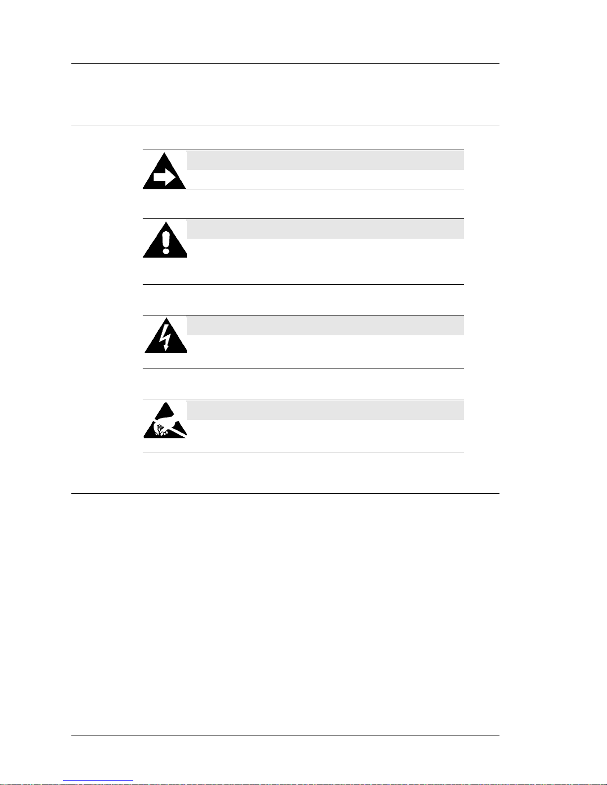
Symbols
Document Design and Production
Desktop Publishing by Adobe FrameMaker
Digital Images: Canon, Nikon
Image Processing: Paint Shop Pro
Line Drawings: CorelDraw
NOTE
This symbol brings special attention to a related item.
WARNING
This symbol indicates that specific handling instructions or
procedures are required to prevent damage to the hardware or
loss of data.
SHOCK HAZARD
This symbol calls attention to a potential hazard that requires
correct procedures in order to avoid personal injury.
STATIC SENSITIVE DEVICES
This symbol indicates that specific ESD handling procedures
are required.
Page 13

PCWS 2015 Setup Guide - 2nd Edition 1-1
Chapter 1
What is the PCWS 2015
This chapter describes the basic hardware and options, then goes on to
describe the software platform.
In this chapter
The System ........................................................................................ 1-2
Features..............................................................................................1-7
Software Platform............................................................................1-14
Power Management States...............................................................1-16
Specifications...................................................................................1-18
Approvals.........................................................................................1-19
Page 14
1-2 PCWS 2015 Setup Guide - 2nd Edition
What is the PCWS 2015
The System
The System
The MICROS PCWS 2015 sets a new standard for performance in a Point of
Sale terminal. Based on the Intel Calpella mobile platform, it provides the
processing power demanded by the latest applications, while at the same time
maintaining a low thermal output and minimal power consumption.
Two dual-core mobile processors from this family are available: the Intel
Celeron P4505 or Core i5-520.
The PCWS 2015 is designed to operate along side the Workstation 5A,
retaining similar styling and compatibility with existing stands, customer
displays, magnetic card readers, biometric devices and other peripherals.
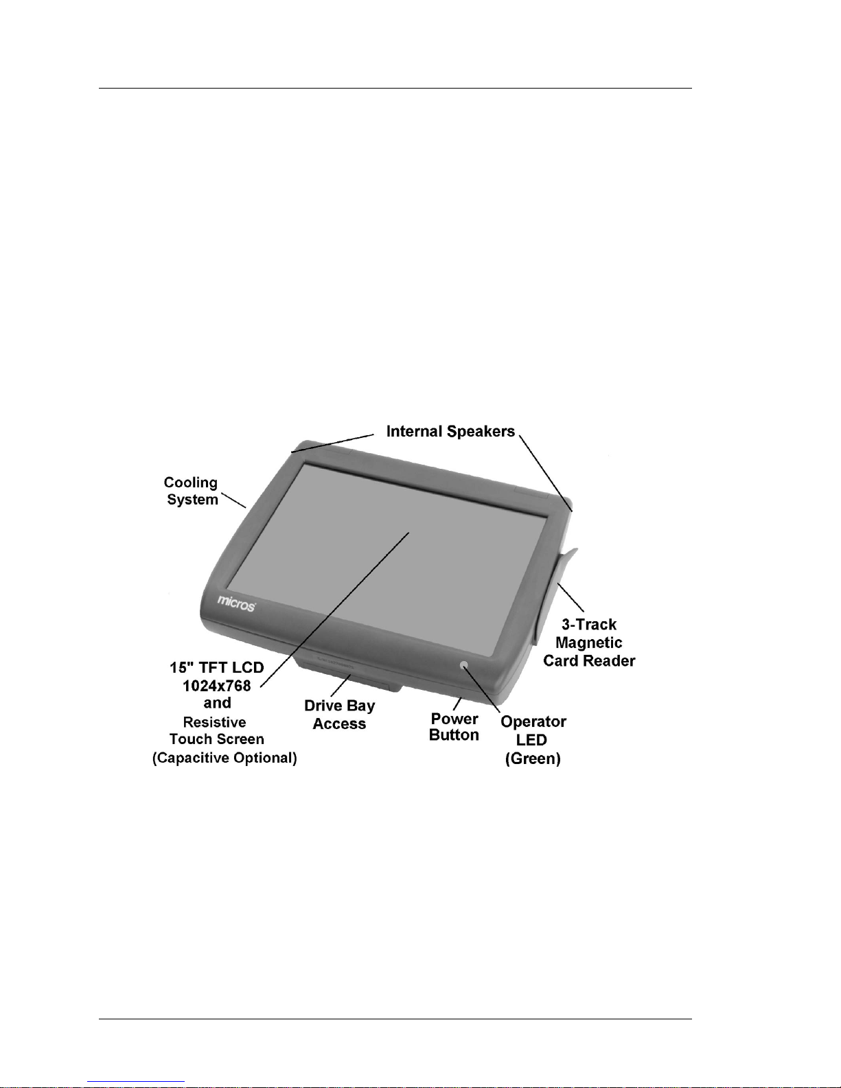
Operator Features
Figure 1-1 points out the primary external operator controls.
Figure 1-1: The PCWS 2015 - Operator Features
15” TFT LCD and Resistive Touchscreen
The Operator LCD consists of a 15” TFT LCD, at a fixed resolution of
1024x768 and is capable of supporting up to 262K colors. Placed over the
LCD is a five-wire resistive touchscreen. An optional capacitive touchscreen
will be available after release.
Page 15

PCWS 2015 Setup Guide - 2nd Edition 1-3
What is the PCWS 2015
The System
Operator LED
The PCWS 2015 Operator LED is Green to easily distinguish the unit from the
Workstation 5A, which shares similar casework.
The Operator LED blinks two times per second as the workstation starts-up
and performs the Power On Self T est (POST). After the operating system starts
and loads the PCWS API, the Operator LED turns solid Green.
Power Button
The recessed illuminated power button is located on the lower right of the base.
It is used to power the PCWS 2015 on and off. The illuminated power button is
identified by the international symbol for power on/off.
3-Track Magnetic Card Reader
The low profile 3-Track Mag Card Reader is the same as used in the
Workstation 5A.
Cooling System
The dual-core Celeron and i5 processor selections consume sufficient power to
require active cooling. After conducting extensive thermal simulations, heat
pipe cooling technology was selected for the PCWS 2015.
Heat Pipes combine the principles of thermal conductivity and phase transition
to efficiently manage the transfer of heat between ‘warm’ and ‘cold’ surfaces.
A heat pipe consists of a sealed pipe or tube made of copper, connected to both
the ‘hot’ and ‘cold’ ends. A vacuum pump is used to remove all air from the
empty heat pipe, and then it is filled with a small amount of coolant chosen to
match the operating temperature.
On the PCWS 2015, the ‘warm’ end of the heat pipe is heatsink attached to the
processor and the ‘cold’ end of the heat pipe is located under the power supply
cover. The power supply cover is shaped to form a ‘cooling tunnel.’
The 60mm CPU fan pulls ambient air through the front of the base, across the
heat pipe radiator and power supply, before it exits from the left side of the
workstation base. This is illustrated in Chapter 3.
The CPU fan runs at full speed when you start the workstation, then slow to
about 2500 RPM in about two minutes. The fan continues to run at this speed
as long as the workstation is on. If the CPU fan temperature sensor exceeds
47°C, the CPU fan will increase speed to compensate.
Internal Speakers
The PCWS 2015 introduces Intel High Definition Audio capability. The digital
audio controller in the PCH is coupled to the analog RealTek ALC268-VB1
High Definition codec.The IO Panel includes a Line-Out audio jack for driving
external powered speakers.
Page 16
1-4 PCWS 2015 Setup Guide - 2nd Edition
What is the PCWS 2015
The System
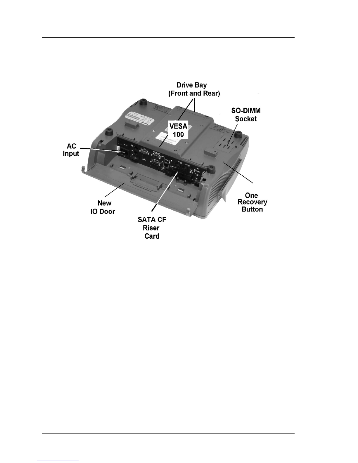
The illustration below points out features located on the bottom of the
workstation.
Figure 1-2: PCWS 2015 Features - Bottom View
Mass Storage
The PCWS 2015 can use standard 2.5” form factor SATA drives, but is also
capable of booting from a USB Hard Drive.
2.5” SATA Drive Bay
The PCWS supports one or two laptop form factor (2.5”) SATA drives,
accessed from the front and rear of the base. The PCWS 2015 ships with a
single 2.5” SATA drive installed in bay 0, near the IO panel. A second
drive can be added for expansion or two drives can be used in combination
to build a RAID 0 or RAID 1 array.
2.5” SATA Solid State Drives (SSD) are available, but are currently
substantially more expensive than spinning drives and not yet available in a
standard PCWS 2015 configuration.
Each bay is secured by access panels with captive allen head screws.
Chapter 3 contains more information about adding and removing hard
drives.
Page 17

PCWS 2015 Setup Guide - 2nd Edition 1-5
What is the PCWS 2015
The System
eUSB Flash Drive
The PCWS 2015 includes a dedicated 2x5 header reserved for an eUSB
flash drive, similar to that used in the Workstation 5 and 5A. This device
can be installed for additional storage and backup purposes. It can also be
configured as boot device and primary storage for POSReady 2009 or
Linux images. eUSB Flash Drives are available in multiple capacities as
described in the PMA.
Compact Flash Card
Like most MICROS workstations, the PCWS 2015 includes an externally
accessible T ype 1 C ompact Flash Card Socket. It is s ecured by a plate held
in place by allen head screws.
Like the USB Flash Drive, a CF card can be used for additional storage and
backup. However, it is not recommended that the CF Card be used as the
primary storage device as this prevents the socket from being used for an
optional Recovery CF.
Optional Recovery CF Cards are available for both POSReady 2009 and
Windows 7 that can return the unit to an out-of-box condition within
minutes. The Recovery CF ships with a current factory image, but
customer specific images can be substituted by simply editing a text file.
Pressing the Recovery Button, accessed through a hole in bottom of the
workstation is detected by the BIOS. On the next power cycle, the BIOS
changes the boot order to boot from the Recovery CF. A recovery script
automatically starts GHOST to transfers the image to the primary storage
device.
Once the image transfer is complete, the unit automatically reboots, the
default boot order is restored and the workstation boots from the primary
storage device.
The PCWS 2015 uses a new CF Riser Card, called the SATA to CF Riser
Card. The new riser card installs in the same physical location as the
original CF Riser Card so that it is accessible from the IO panel, but does
not use the same system board connector used by the original CF Riser
Card, which it replaces.
See Chapter 3 for more information about the SATA to CF Riser Card.
Memory Expansion
Current PCWS 2015 configurations ship with a single 2GB DDR3 SO-DIMM
installed in socket SO-DIMM1, located on the top of the system board.
Removing a small door on the bottom of the workstation exposes the second
SO-DIMM socket. Adding a second 2GB DDR3 SO-DIMM can increase the
total memory size to 4GB.
Page 18

1-6 PCWS 2015 Setup Guide - 2nd Edition
What is the PCWS 2015
The System
AC Input
The IO Panel AC Input connector is similar to that used on the Workstation
5/5A, and uses the same angled AC input connector compatible with the
Workstation 5 and 5A Adjustable Stand.
IO Door
To accommodate the 10mm increase the overall height of the base, the 2015
uses a new IO Door. The new door features a flexible tab on one end to ease
removal and installation.
VESA 100 Mount
The VESA 100 compatible mount on the base of the PCWS 2015 can support
virtually any mounting from under a shelf to wall mount or an adjustable arm.
Page 19

PCWS 2015 Setup Guide - 2nd Edition 1-7
What is the PCWS 2015
Features
Features
This section discusses the standard IO capabilities and expansion options
available for the PCWS 2015.
Expansion Capabilities
This section lists both IO Panel and system board expansion connectors.
Serial Ports
The PCWS 2015 features a total of 4 serial ports, configured in the following
manner.
2 DB9 Serial Ports, COM1 and COM2.
• COM1 offers BIOS selectable +5V, +9V and +24V outputs.
• COM2 is a non-powered DB9 serial port.
COM4 IDN Port. RJ45 Modular Connector combines an RS422/RS232
Interface. This port can be used for IDN printers, serial printers or other serial
peripherals.
COM5 Modular RS232 Port. RJ45 ‘full-featured’ RS232 interface supports a
number of peripherals and interfaces.
USB Ports
The PCWS 2015 features a wide selection of available external USB ports on
the IO Panel and internal headers located on the system board.
Type A USB Ports
A total of four Type A USB connectors (USB1 - USB4) are available at the
IO Panel for general purpose use. With the addition of the USB Extension
Cable option one USB port can be made available at the front of the
optional Adjustable Stand.
Powered USB Ports
The PCWS 2015 IO panel includes two unique powered USB ports. Unlike
standard powered USB, these ports are not constrained to a single voltage
and are smaller than traditional powered USB ports.
The port voltage is determined by the dongle connected to it. One port can
provide either +5V, +12V, or +24V ; the second port can provide either +5V
or +12V.
Typical uses for these ports are powered USB peripheral such as the
Protege Display System. MICROS has tested the Epson TM-T88V
Powered USB Printer on port USB5. This implementation is shown on the
next page.
Page 20
1-8 PCWS 2015 Setup Guide - 2nd Edition
What is the PCWS 2015
Features
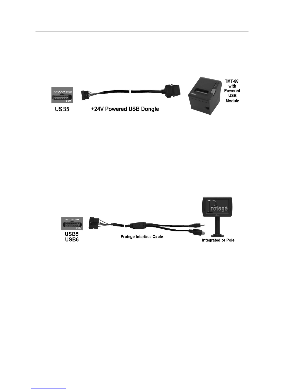
Figure 1-3 shows the proprietary Powered USB implementation with a six
foot custom powered USB Cable connected between the workstation and
the USB module of the Epson TM- T88V thermal printer.
Figure 1-3: Powering the TM-T88V from the optional +24V Powered USB Dongle
+5V and +12V Powered USB Dongles are also available. See the
Specifications page for more details on voltages and available power.
Figure 1-4, below shows the optional MICROS Protege Customer Display
System connected to the USB5 or USB6 ports using a custom cable that
carries both USB port data and +12V to operate a new class of intelligent
USB peripheral devices.
Figure 1-4: MICROS Protege Customer Display Connected USB5 or USB6
System Board USB Headers
A total of seven 2x5 USB headers are located on the System Board. One is
dedicated to the optional eUSB flash drive, and one port is dedicated to the
resistive or capacitive touch controller. This leaves additional headers
available for options such as the integ rated biometric fingerprint reader and
or an 802.11 compatible USB WiFi card.
USB Port Security
All IO Panel USB ports can be individually disabled to prevent the use of
keyboards, flash drives or other USB devices. USB per-port control is
currently implemented in the BIOS. Future versions of the 2015 will allow
USB per-port control through the PCWS API.
Page 21

PCWS 2015 Setup Guide - 2nd Edition 1-9
What is the PCWS 2015
Features
Mini-PCI Socket
The System Board Mini-PCI socket can accommodate one of two available
options, listed below.
• 802.11 a/b/g/n Wireless Card.
• Mini-PCI Modem
The Mini-PCI Modem can be used with WIN32 operating systems, and is
certified for use in North America.
• Future Products.
Page 22
1-10 PCWS 2015 Setup Guide - 2nd Edition
What is the PCWS 2015
Features
Workstation Mounting Options
The mounting options available for the Workstation 5 and 5A also apply to the
PCWS 2015.
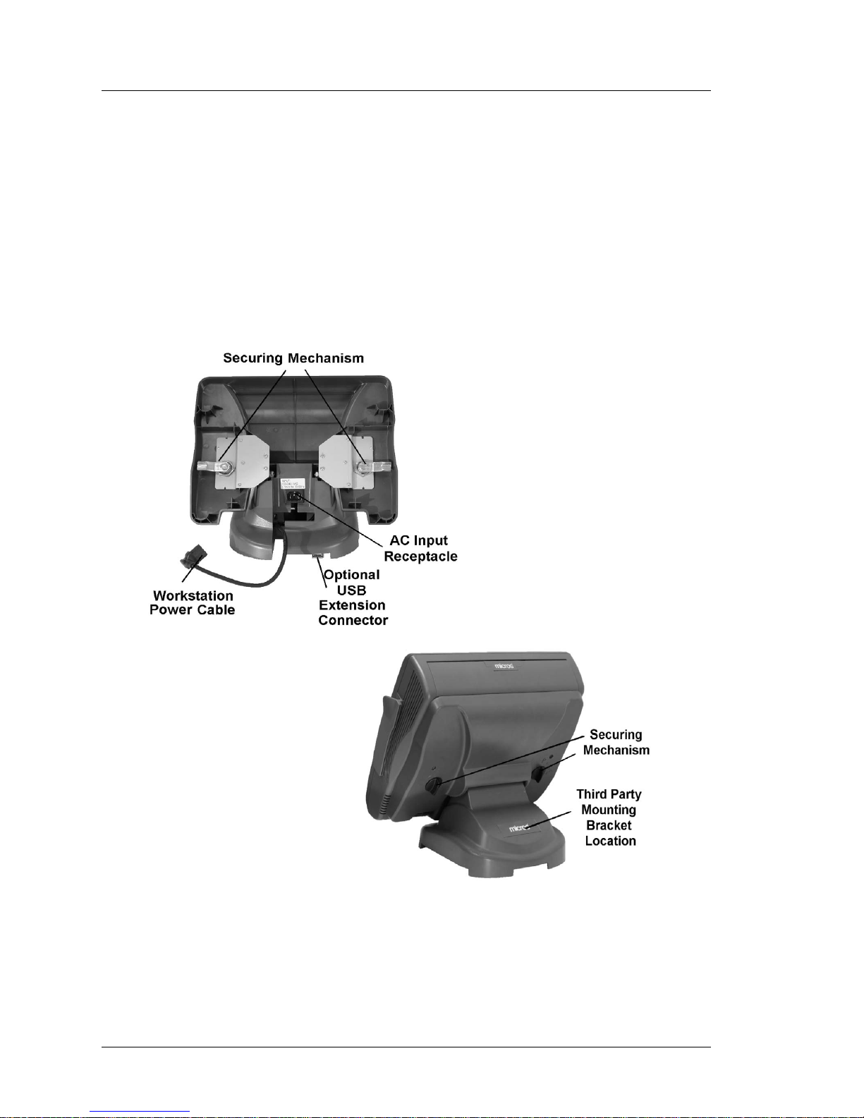
The Adjustable Stand
The Adjustable Stand converts the low profile PCWS 2015 into an
adjustable display design. The stand has a weighted base for stable
operation, generous cable area, a compartment for storing a printer power
supply, and locking hinges to allow the workstation to be positioned
between 25° and 70°.
Figure 1-5: The Adjustable Stand
The rear of the stand includes a pair of knobs that secure the workstation to the
stand. The base includes a knock-out for a custom bracket that supports third
party peripherals.
Page 23
PCWS 2015 Setup Guide - 2nd Edition 1-11
What is the PCWS 2015
Features
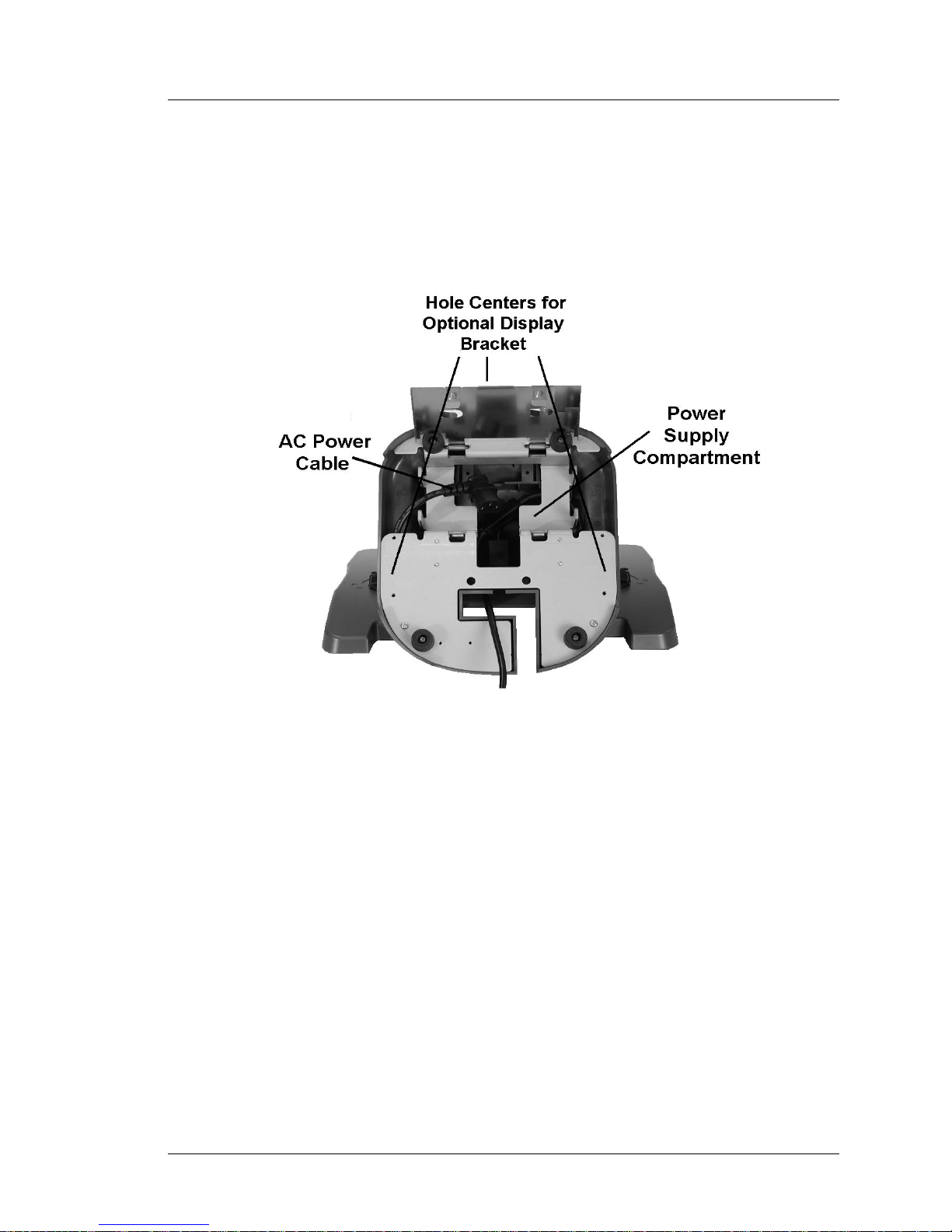
Power Supply Compartment
Figure 1-6, below shows a view of the stand base plate and the
compartment for housing an optional Printer Power Supply. AC power is
connected to a receptacle in the throat of the stand using a low profile
angled connector. An internal ‘Y’ cable distributes power to both the
workstation and printer power supply compartment.
Figure 1-6: Adjustable Stand - Power Supply Compartment
Three pairs of mounting holes are provided at the left, right and rear of the
plate sized for optional Adjustable Stand Mounting Bracket.
Page 24
1-12 PCWS 2015 Setup Guide - 2nd Edition
What is the PCWS 2015
Features
LCD Customer Display Options
The PCWS 2015 supports the 240x64 LCD Customer Display and the Protege
Customer Display System. Integrated, Pole and Adjustable Stand Mounted
versions are available, as detailed in the following pages.
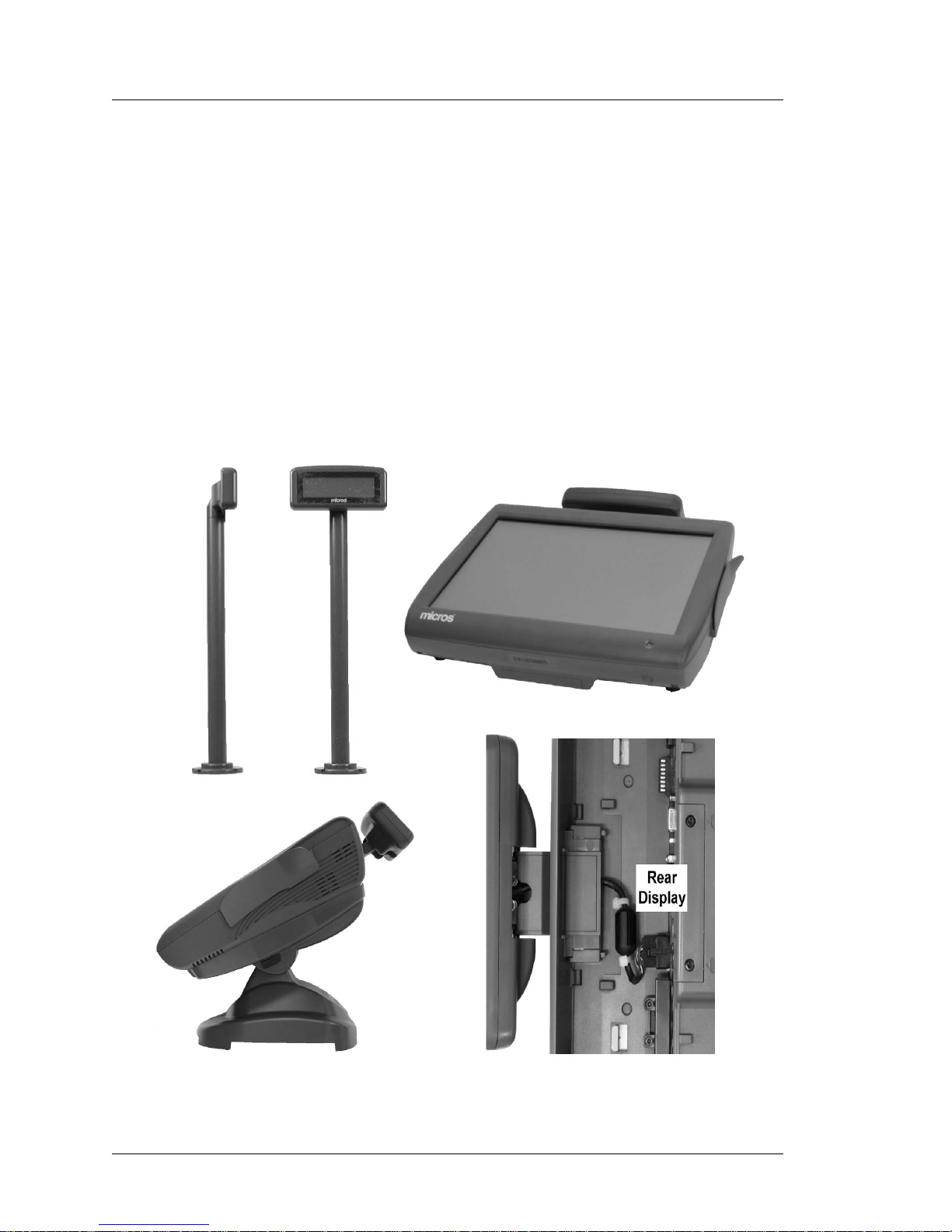
240x64 LCD Customer Display
This display is based on a 240x64 monochrome STN LCD and companion
LCD control board. It can emulate the 2x20 VFD Customer Display or
operate in full graphics mode.
Figure 1-7 displays Integrated and Pole versions of the 240x64 LCD
Customer Display. The lower right hand corner shows how the integrated
version receives power and data through the IO Panel Remote Display
Connector.
Figure 1-7: The 240x64 LCD Customer Display
Page 25
PCWS 2015 Setup Guide - 2nd Edition 1-13
What is the PCWS 2015
Features
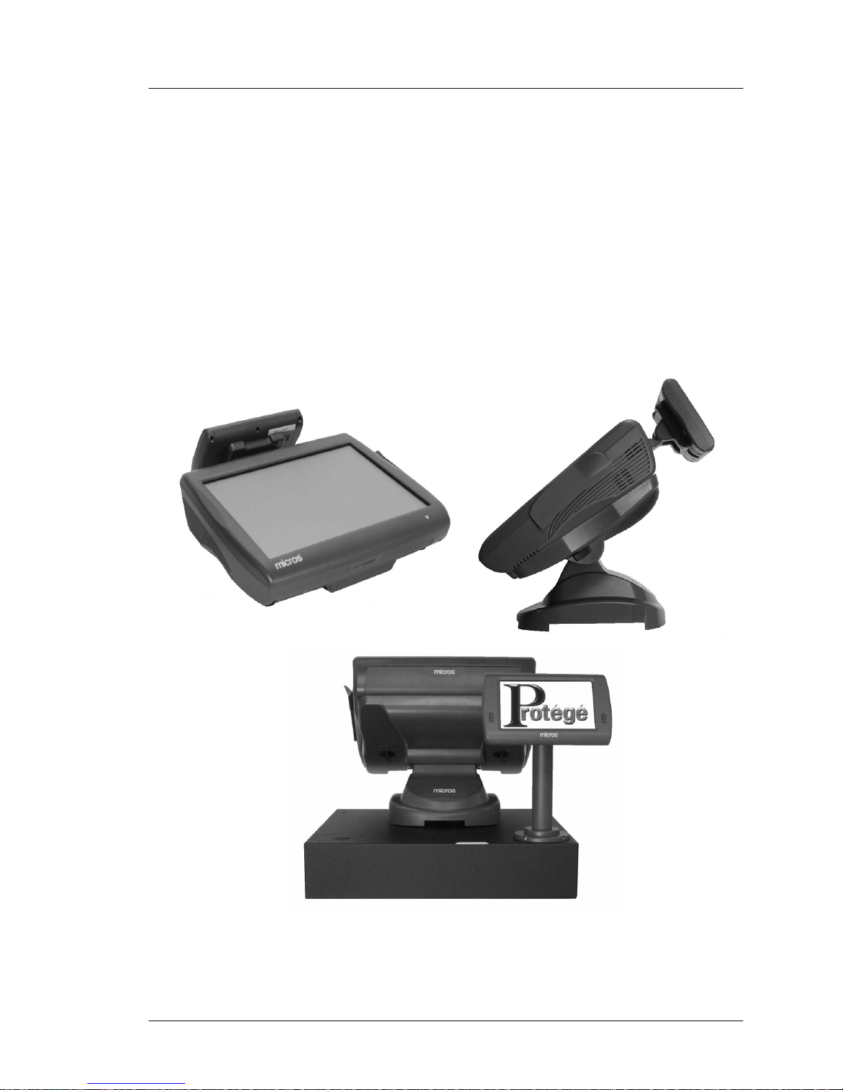
Protege LCD Customer Display System
The MICROS Protege Customer Display System is a customer facing 7”
LCD, providing a greater level of detail than traditional 2x20 VFD or the
MICROS 240x64 graphical LCD.
The Protege is an intelligent display, featuring a microprocessor, internal
Flash and RAM storage, and LCD controller. For the user, the Protege is
equipped with a 7” 800x400 TFT LCD, 4-wire resistive touch screen,
stereo speakers, internal microSD Card, and room for future expansion.
The Protege displays full transaction detail, allowing customers to c onfirm
accuracy and improve speed of service in fast transaction environments.
During idle times, the Protege can display customized visual content (e.g.
slide shows), for use as a marketing and advertising tool.
Figure 1-8: The Protege Customer Display System
Page 26

1-14 PCWS 2015 Setup Guide - 2nd Edition
What is the PCWS 2015
Software Platform
Software Platform
Software components include the BIOS, Operating System, the PCWS API,
platform specific drivers, and utilities. These components are pre-installed on
each unit to create a foundation upon which POS applications are installed
using the Client Application Utility (CAL).
BIOS
The PCWS 2015 is based on the Phoenix SecureCore Tiano (SCT) BIOS. It is
built on a decade of support for industry initiatives to handle the widest
possible range of processors chip set and IO interfaces. The BIOS includes a
pre-boot environment called UEFI (Unified Extensible Firmware Interface) to
provide optional features such as CF Recovery.
Operating Systems
Operating Systems supported by the PCWS 2015 includes both 32 and 64-bit
versions Windows 7 Professional Embedded or Windows Embedded
POSReady 2009. Formerly known as Windows Embedded for Point of Service
(WEPOS), Windows Embedded POSReady 2009 is derived from W indows XP
Professional, and tailored for the point of service environment.
Additionally, a Windows XP Professional image will be available for those
who wish to downgrade from Windows 7 Professional.
PCWS API and MICROS OPOS Drivers
The PCWS API is used by MICROS applications to control MICROS specific
ports such as the cash drawers, IDN printers, customer displays and mag card
reader. The API also controls the operator display brightness and operator
LED, while the most recent version included with the PCWS 2015 adds the
ability to enable/disable the external USB ports.
Third party application designers can choose to utilize the PCWS API to
directly control these ports or use the MICROS OPOS (Open POS) drivers.
The MICROS OPOS drivers provide third party application developers an
industry standard structure for controlling point of sale peripherals. The OPOS
drivers interact with the PCWS API in place of controlling the ports directly.
The MICROS OPOS drivers are included in the POSReady 2009 and W indows
7 Professional images, but not installed.
PCWS 2015 Diagnostics Utility
Utilities included with the PCWS 2015 include the WIN32 Client Application
Loader (CAL), and an updated Diagnostics Utility for testing the unit.
Page 27

PCWS 2015 Setup Guide - 2nd Edition 1-15
What is the PCWS 2015
Software Platform
MICROS CAL32
The MICROS CAL32 provides many of the same application level
functionality as the MICROS CE based CAL Client, but does not perform
operating system or platform updates. CAL32 can be used to install MICROS
client applications and updates, as well as PCWS 2015 drivers and utilities.
CAL 32 is included with all factory images, but is not installed.
Simphony Prerequisite Software
To simplify the installation of Simphony applications, the MICROS PCWS
2015 platform is pre-loaded with most of the prerequisite required by
Simphony, including SQL Express, Visual C++ 2008 Runtime, and POS for
.NET.
POS Application
The PCWS 2015 is shipped without a Point of Sale application installed. The
MICROS Client Application Loader (CAL) included with each unit can
connect to any MICROS application server and download the application in
minutes.
The table below summaries the applications that have tested.
Disk images for MICROS PC Workstations are posted in the Member Login
Area of the MICROS Web Site: Members -> Product Support -> Hardware ->
Downloads, Disk Images.
Intel AMT
Intel Active Management Technology is the next generation of advanced
manageability features developed as a direct result of IT customer feedback
gained through market research. Intel AMT reduces the TCO Total Cost of
Ownership (TCO) through features such as asset tracking and remote
manageability. Intel AMT extends the manageability capability for IT through
Out Of Band (OOB) operation, allowing asset information, remote diagnostics,
and recovery on client systems even when they are in the ACPI S5 (Soft-Off)
state, or in situations where the operating system hangs.
Operating
System
RES/3700 LES/9700 Simphony
POSReady
2009
All 4.X as Client &
Server
RES 5.0 Client Only
9700 V3.6
Client
As Client on
Simphony
1.x and 2.x
Windows 7
Professional
RES 5.0 as Client &
Server
TBA As Client on
Simphony
2.X
Page 28

1-16 PCWS 2015 Setup Guide - 2nd Edition
What is the PCWS 2015
Power Management States
Power Management S tates
Introduction
This section introduces the PCWS 2015 power management states.
References to power management states are specified in bold capital letters,
e.g., NOPOWER, and ON. See chapter 3 for more information about operating
the PCWS 2015.
UNPLUGGED
• The AC power cord is not connected to a wall outlet. This state is also
referred to as “ACPI G3 Mechanical Off.”
• The Operator LED is Off.
• The Operator LCD is blank.
The workstation can be safely disassembled when in this state.
NOPOWER
• The AC power cable is attached, but the operating system and applications
are not running. RAM contents are undefined.
• The Operator LED is Off.
• The Operator LCD is Blank.
This is the ACPI S5 ‘soft-off’ state where the power supply remains active,
delivering minimal power to several key circuits in order to detect the
power-button, recovery button or Wake-On-Lan event.
It is not safe to disassemble the workstation when in this state. Power supply
components remain energized, presenting a shock hazard. Always remove the AC
power cord from the IO Panel before disassembling the PCWS 2015.
ON
• The Operating System and POS application are operating. RAM contents
are maintained.
• The Operator LED is solid Green.
Standby and Hibernate
Standby is available with POSReady and the more advanced Hibernate is
available with Windows 7 Professional. Both power saving modes are
supported at the hardware level, but may not be supported in some POS
applications.
Last Power State Retention
The PCWS 2015 retains the last power state (ON or NOPOWER) in non-volatile
memory . In B IOS Setup, the Power Failure Resto ration field in the Advanced Special Configuration menu determines how the unit behaves when AC power
to the workstation fails and then returns.
Page 29

PCWS 2015 Setup Guide - 2nd Edition 1-17
What is the PCWS 2015
Power Management States
The default setting of ‘Last State’ means that if the workstation is ON and AC
power fails, it returns to ON when AC power is restored with no action required
by the operator. See Chapter 3 for more information.
PCWS 2015 Power Management State Ta ble
Figure 1-9: PCWS 2015 Power Management States
Current State Event Source Scenario New State
1 UNPLUGGED AC Power AC Power becomes
available and the last
recorded state was not the
ON state.
NOPOWER
2 NOPOWER Operator The operator presses the
power button for less than 1
seconds.
ON
3 NOPOWER Operator The operator presses the
power button for more than
4 seconds.
ON
4 NOPOWER Server
Application
A server application sends a
‘Wake On LAN’ command.
ON
5ON Operator The operator presses the
power button for more than
4 seconds.
NOPOWER
6ON Application The application shuts down
the workstation.
NOPOWER
7ON Server
Application
A server application sends a
“Wake On LAN” command.
ON
8ON Application Warm boot is called by the
CAL.
NOPOWER
then ON
9 NOPOWER AC Power
Failure
AC Power fails and restored NOPOWER
10 ON AC Power
Failure
AC Power fails and is
restored
ON
Page 30

1-18 PCWS 2015 Setup Guide - 2nd Edition
What is the PCWS 2015
Specifications
Specifications
The PCWS 2015 conforms to the following specifications.
Specification Parameters
Processor Selections Intel Celeron P4505, Dual Core 1.8GHz, or
Intel i5-520, Dual Core, 2.4GHz
IO Controller QM57 Platform Controller Hub
Display 15” TFT LCD (1024x768)
Touchscreen EloTouchSystems Five-wire resistive, 100
thousand points-per-square inch resolution
rated at a screen life of over 35 million
touches in one location.
Capacitive option available.
Display Backlights LED Backlights with three intensity settings
programmable through the PCWS API.
Real Time Clock 100-year calendar with alarm features and
century roll-over, includes 242 bytes of battery
backed CMOS RAM.
Memory 2 SO-DIMM Sockets - Max 8GB DDR3 1066
Mag Stripe Reader 3-Track ABA compatible.
Optional Customer Displays 240x64 STN graphics based LCD
Protege Customer Display System
USB Ports Fourteen USB 2.0 Ports
> Eight Internal
> Six external (Four USB type A, two MICROS
Powered USB). External USB ports can be
disabled.
LAN Interface 10/100/1000 Ethernet - Modular RJ45
Serial Ports 1 DB9 RS232 Powered Serial w/ handshake
1 DB9 RS232 Serial /w handshake
1 Modular RS232 Serial /w handshake
1 Modular RS422/RS232 Serial (IDN)
Input Voltage Universal Input - 85 to 264VAC, 47 to 63Hz.
Input Power 35W Typical
BTU/Hour 120 Typical, 290 Maximum
Storage Temperature -25°C (-13°F) to 80°C (176°F)
Operating Temperature 0°C (32°F) to 45°C (113°F), 90% relative
humidity max
Page 31

PCWS 2015 Setup Guide - 2nd Edition 1-19
What is the PCWS 2015
Approvals
Approvals
The PCWS 2015 meets the following safety and environmental certifications.
Weight 10.5 lbs. (4.7 kg) / Shipping weight 14.0 lbs.
(6.35 kg)
Case Material PC-ABS Plastic
Physical Dimensions See Appendix A
Directive Specification Year
Safety EN 60950-1:2006+A11+A1 2010
(2006/95/EC) IEC 60950-1:2005+A1 2010
EMC EN 55022:2006 2006
(2004/108/EC) EN 55024:1998+A1+A2 2003
EN 61000-3-2:2006 2006
EN 61000-3-3:2008 2008
Specification Parameters
Page 32

1-20 PCWS 2015 Setup Guide - 2nd Edition
What is the PCWS 2015
Approvals
Page 33

PCWS 2015 Setup Guide 2-1
Chapter 2
PCWS 2015 BIOS
This chapter describes the PCWS 2015 BIOS. Supported BIOS
Versions include:
• O1201r (Revision C System Board Only)
• O1301 (Revision C System Board Only)
• O1301g (Revision D or later System Boards Only)
In this chapter
Starting BIOS Setup Utility...............................................................2-2
System Information Screen................................................................2-4
Advanced ...........................................................................................2-6
Boot..................................................................................................2-33
Exit...................................................................................................2-35
Page 34

2-2 PCWS 2015 Setup Guide - 2nd Edition
PCWS 2015 BIOS
St arting BIOS Setup Utility
Starting BIOS Setup Utility
This section describes how to start and use the Phoenix SecureCore Tiano
Setup Utility.
Warning: Many of the Setup Screens contain fields which could cause the
workstation to malfunction if set incorrectly. MICROS recommends you do
not change BIOS fields unless specifically instructed to do so.
• PCWS 2015 specific settings are contained in the Advanced -> Special
Menu.
• To control the IO Panel USB Ports through the BIOS, refer to page 2-20.
PCWS 2015 BIOS Version and System Board Compatibility
The table below describes BIOS compatibility with system board revision.
System Board Revision C
• Requires BIOS Versions O1201r or O1301.
These versions can only be used System Board Revision C. Not compatible
with System Board Revision D.
System Board Revision D (or later)
• Requires BIOS Version O1301g or later.
The Revision D System Board includes the following hardware changes
that require the new BIOS.
• USB Port Switches controlled by GPIO lines to manage the IO Panel
USB Ports from the Diagnostics Utility or BIOS.
• The Powered USB voltages on USB5 and USB6 are cycled on-off-on
when the workstation is rebooted.
O1201r O1301 O1301g
Revision C Revision C Revision D
Page 35

PCWS 2015 Setup Guide - 2nd Edition 2-3
PCWS 2015 BIOS
Starting BIOS Setup Utility
Starting BIOS Setup
1. Connect a USB Keyboard to one of the USB ports located on the IO panel.
2. Power-up or restart the PCWS 2015 using the power button.
3. Just as the BIOS Splash screen with MICROS logo appears, press the [F2]
key.
The current MICROS BIOS Version is displayed in the upper left hand
corner of the splash screen.
A section of the Phoenix SecureCore Tiano Setup Main screen shown
below appears.
Figure 2-1: PCWS 2015 BIOS Setup Main Screen (O1301g or later)
4. To adjust the System Date and Time, follow the help instructions shown at
the bottom of the screen.
5. T o vi ew the System In formation Screen, scroll to the ‘System Information’
selection and press Enter.
Page 36

2-4 PCWS 2015 Setup Guide - 2nd Edition
PCWS 2015 BIOS
System Information Screen
System Information Screen
The System Information Screen for each processor configuration is shown in
Figure 2-2.
Figure 2-2: PCWS System Information Screen (i5 Core and P4505 Processors)
BIOS Version and Build Time
The MICROS BIOS Version and build time are displayed.
Processor Ty pe an d Spee d
The Processor Number and Clock Speed are displayed in this field. Two
processors are available, listed below .
• i5 520E @ 2.40GHz.
• Celeron P4505 @ 1.8GHz.
Page 37

PCWS 2015 Setup Guide - 2nd Edition 2-5
PCWS 2015 BIOS
System Information Screen
System Memor y Speed
Displays the Memory ‘Front Side Bus’ speed.
L2 Cache RAM
Displays the L2 Cache size.
Memory Mode
The processor selections feature a dual channel memory controller for
improved performance. The memory controller runs in the Dual-Channel
symmetric or interleaved configuration when two SO-DIMMs are
installed. In this configuration, memory, addresses are ping-bonged
between each channel after each cache line.
Memory Channel A Slot 0
This field displays the SO-DIMM installed in the SO-DIMM1 socket.
Memory Channel B Slot 0
This field displays the SO-DIMM installed in the SO-DIMM2 socket.
Page 38

2-6 PCWS 2015 Setup Guide - 2nd Edition
PCWS 2015 BIOS
Advanced
Advanced
The Advanced tab contains the majority of BIOS settings listed under a
number of headings shown in Figure 2-3, below.
Figure 2-3: PCWS 2015 BIOS Advanced Menu (Version O1201r)
Note: All PCWS 2015 specific fields are contained in the ‘Special
Configuration’ Menu.
Select Language
Three selections are available.
Page 39

PCWS 2015 Setup Guide - 2nd Edition 2-7
PCWS 2015 BIOS
Advanced
Boot Configuration
The Boot Configuration menu contains fields that determine how information
is displayed at boot time, provide support for legacy USB devices, and enables
console redirection for debugging.
Figure 2-4: Advanced - Boot Configuration
Quick Boot [Disabled]
Enables time-optimized POST, causing certain pre-configured OEM
optimizations to be made when the system boots.
High Resolution Graphics [Enabled]
Enables High Resolution Graphics BIOS Splash Screen.
Diagnostics Splash Screen [Disabled]
Enables a Graphical POST, including animation, sound, icons,
advertisements, and other multi-media objects that may be configured by
the OEM. On the PCWS 2015, this is confined to the Blue splash screen
with MICROS logo. The BIOS Version is displayed in the upper left corner
of the splash screen.
Diagnostics Summary Screen [Disabled]
Enables the diagnostic summary screen. The default setting of [Disabled]
decreases the boot time.
BIOS Level USB [Enabled]
Enables BIOS support for USB Keyboards and Mice.
Page 40

2-8 PCWS 2015 Setup Guide - 2nd Edition
PCWS 2015 BIOS
Advanced
USB Legacy [Enabled]
Enables support for USB devices such as keyboards and mice, but adds
support for mass storage.
Console Redirection [Disabled]
Console Redirection is a debug feature where the display console is
redirected over a serial port.
[Enabled] - causes the BIOS to always use the serial port as the
console, without testing for the presence of the terminal emulation
program.
[Disabled] - causes the BIOS to never invoke console redirection, but
instead always use the main keyboard and video display.
UEFI Boot [Enabled]
This selection enables the Unified Extensible Firmware Interface, a
specification that defines a software interface between an operating system
and platform software. The UEFI Specification is developed by the Unified
EFI Platform Forum, an industry-wide organization. UEFI specification
2.3, was approved in May 2009.
UEFI is not restricted to a partic ular processor architecture, and can run on
top of or in place of traditional BIOS implementations. The Phoenix
SecureCore Tiano BIOS fully supports the UEFI implementation.
UEFI includes a pre-boot environment capable of selecting a boot device
and booting to the operating system, a key feature for using the Recovery
CF.
Legacy Boot [Enabled]
When Enabled, this option will skip some tests to speed up the POST.
Load OPROM [On Demand]
Load all Option ROMs or on demand according to the boot device.
Boot Priority [UEFI First]
Select the priority of the boot option between UEFI and legacy devices.
Page 41

PCWS 2015 Setup Guide - 2nd Edition 2-9
PCWS 2015 BIOS
Advanced
ACPI Configuration
The PCWS 2015 defines two thermal zones, SYS and CPU. Each zone
contains a sensor coupled to fan controllers located in the Super IO. At
start-up, the BIOS configures the fan controllers using the default active trip
points for the CPU and SYS fans.
Figure 2-5: Advanced - ACPI Configuration Fields
Active Trip Point SYS Fan
This field displays the temperature at which the SYS thermal zone
activates the SYS fan. The SIO SYS fan controller continuously compares
the system zone temperature to the SYS Active Trip Point. When the
system temperature reaches 55°C (131°F), the fan starts. As the fan runs,
the SYS fan thermal zone will cool to below 55°C and the fan slows down.
Note: the SYS Fan may not be installed on later production units.
Active Trip Point CPU Fan
This field displays the temperature at which CPU thermal zone increases
the CPU fan speed. At start-up, the BIOS programs the controller to run the
CPU fan at a continuous speed of about 2500RPM.
When the CPU zone temperature (as measured by T2, located near the
CPU) exceeds the trip point value of 47°C, the CPU fan speed increases.
When the increased fan speed brings the zone temperature below 47°C, the
CPU fan speed returns to about 2500RPM.
Page 42

2-10 PCWS 2015 Setup Guide - 2nd Edition
PCWS 2015 BIOS
Advanced
Passive Trip Point [95C]
If the processor exceeds the Passive Trip Point Temperature the passive
cooling policy is implemented. This may result in processor clock speed
throttling.
Passive TC1 Value [1]
The Passive Thermal Compares Value is used as a constant for the TC1
Passive Cooling formula.
Passive TC2 Value [5]
The Passive Thermal Compares Value is used as a constant for the TC2
Passive Cooling formula.
Passive TSP Value [10]
The Passive Thermal Sampling Period value (in tenths of seconds) is used
used to implement the Passive cooling equation. TSP along with TC1 and
TC2, enables the proper hysteresis required by the system to accomplish an
effective passive cooling policy.
Critical Trip Point [POR]
The Critical Trip Point is the temperature at which the operating system
performs a critical, but orderly shutdown of the system. The default value
‘POR’ is the Plan of Record for the installed processor.
HPET Support [Enabled]
The PCH contains two High Precision Event Timers (HPET) used for
ACPI Interrupt Mapping.
HPET Memory Map BAR (Base Address Registe r) [0FED0000]
Indicates the HPET Memory Map Base Register Address.
Enabled PTID [Disabled]
Enable or Disable Power and Temperature Instrumentation Details.
FACP - PM Timer Flag Value [Disabled]
FACP (Fixed ACPI Description Table) includes various fixed length
entries that describe the ACPI features of the hardware.
The Fixed ACPI Description Table starts with the FCAP signature. The
FADT describes the implementation and configuration details of the ACPI
hardware registers on the platform.
Page 43

PCWS 2015 Setup Guide - 2nd Edition 2-11
PCWS 2015 BIOS
Advanced
Processor Configuration
This screen contains many processor related settings summarized in Figure
2-6, below.
Figure 2-6: Processor Configuration and Power Management
Active Processor Cores [All]
Enable all available processors and threads.
Intel (R) HT Technology [Enabled]
Hyper-Threading Technology allows an execution core to function as two
logical processors. The feature must be enabled in the BIOS and requires
operating system support.
Some execution resources such as caches, execution units, and busses are
shared, each logical processor has its own architectural state and its own set
of general purpose registers and control registers.
Enabled XD [Enabled]
Enable or Disable Memory segregation for improved security.
Machine Check [Enabled]
Enable or Disable Machine Check exception handling.
Page 44

2-12 PCWS 2015 Setup Guide - 2nd Edition
PCWS 2015 BIOS
Advanced
Fast Strings [Disabled]
Enable or Disable Processor Fast Strings.
Intel (R) Virtualization Technology [Disabled]
Intel Virtualization Technology (Intel VT) makes a single system appear as
multiple independent systems to software. This allows multiple,
independent operating systems and applications to be running
simultaneously on a single system.
Intel VT comprises technology components to support virtualization of
platforms based on Intel architecture microprocessors and chip-sets.
Virtualization allows the creation of one or more partitions on a single
system. This could be multiple partitions in the same operating system, or
there can be multiple operating systems instances running on the same
system, offering benefits of consolidation, legacy migration, activity
partitioning or security.
Processor Power Management
Scroll to the Processor Power Management selection and press Enter to
view the following fields.
P-States (GV3) [Enabled]
Enable or Disable Processor Performance States. ACPI supports
placing the system processor cores into one of four power states while
in the working (G0) state.
Boot Performance Mode [Auto]
Configures the max performance state at power up.
C-States [Enabled]
Enable or Disable Processor C-States.
When the processor is idle, low power idle states (C-states) are used to
save power. The higher the c-state, the more power saving actions are
performed.
Systems like the PCWS 2015 implement C-states by having the
processor control the states. The chipset exchanges messages with the
processor as part of the C-state flow.
Extend C-States [Disabled]
Enable or Disable ACPI 2.0 or later support for extended power states
beyond C3. C States are processor power management states.
C6 - State [Disabled]
Enable or Disable deep power saving mode.
Page 45

PCWS 2015 Setup Guide - 2nd Edition 2-13
PCWS 2015 BIOS
Advanced
FACP - RTC S4 Flag Value [Enabled]
Controls the value for the RTC S4 flag in the FACP table.
Enabled - The RTC alarm can wake the system from the S4 state.
Disabled - The RTC alarm can wake the system from the S1, S2, or
S3 sleep states.
APIC - IO APIC Mode [Enabled]
Enable or Disable the Advanced Programmable Interrupt Controller
(APIC) - IO APIC Mode.
ALS Support [Legacy]
Specifies the type of ACPI support.
Legacy - ALS support through the IGT INT10 function.
ACPI - ALS support through an ACPI ALS driver.
EMA Support [Disabled]
Enable or Disable the EMA device in an ACPI environment.
MEF Support [Disabled]
Enable or Disable the ‘Mobile East Fork’ support in an ACPI
environment.
ACPI 3.0 T-States [Disable]
Enables all ACPI 3.0 T-States.
Peripheral Configuration
The Peripheral Configuration fields are listed below.
Spread Spectrum Clock [Disabl ed]
Enable or Disable the Spread Spectrum clock chip feature.
Enable CRID [Disabled]
The CRID (Compatible Revision ID) is an 8-bit hard-wired value assigned
by Intel during the manufacturing process. Normally, the value assigned as
the CRID will be identical to the SRID (Stepping Revision ID) value of the
previous stepping of the product with which the new product is deemed
compatible.
PCIe SR-IOV Support [Disabled]
Enables support for a ‘Single Root I/O Virtualization’ which enables
sharing of a single I/O device among multiple virtual machines.
Page 46

2-14 PCWS 2015 Setup Guide - 2nd Edition
PCWS 2015 BIOS
Advanced
HDD Configuration
The entire HDD Configuration screen is shown in Figure 2-7, below. Scroll
down to view the drives installed in each Serial ATA port.
Figure 2-7: HDD Configuration Screen (BIOS O1201r and O1301)
SATA Device [Enabled]
Enables the SATA Controller in the QM57 PCH.
Interface Combination [AHCI]
Determines the SATA Controller’s operational mode. Three selections are
supported.
IDE - Integrated Device Electronics. Legacy Disk standard, supported
by the BIOS for compatibility with older operating systems.
AHCI - Advanced Host Controller Interface. A new SATA
programming interface developed through a joint industry effort. AHCI
defines transactions between the SATA controller and software and
requires an operating system such as Windows 7 to support all features.
Page 47

PCWS 2015 Setup Guide - 2nd Edition 2-15
PCWS 2015 BIOS
Advanced
RAID - Redundant Array of Inexpensive Drives. The QM57 PCH
provides several diverse RAID options. With a limit of two drives, the
PCWS 2015 can support RAID Level 0 (Performance) or RAID Level
1 (Mirroring) configurations. See Chapter 3 for more information about
the supported RAID configurations.
Enabled SATA Controller SALP [Disabled]
Enable the SATA Controller Aggressive Link Power Management feature.
When enabled, the SATA controller supports auto-generating link requests
to the partial or slumber states when there are no commands to process.
The following three fields are available for each of the six SATA Ports 0
through 5. Most of these features are not supported.
SATA Port 0...5 External Port [Disabled]
When enabled, the controller treats the selected port as an external port.
This feature is not available on the PCWS 2015.
SATA Port 0...5 Hot Plug [Disabled]
When enabled, the selected port is designated hot pluggable. Note: this
requires hardware support to function properly.
SATA Port 0...5 Port Multiplier [Disabled]
When enabled allows a single SATA port to support multiple drives, a
feature that is not supported on the PCWS 2015.
Serial ATA Port 0 [ID String - if installed]
Displays the ID String of the SATA HDD/SSD ins talled in the PCWS 2015
Drive Bay 1 (Rear) in this example, an Intel X25-V 40GB Solid State
Drive is installed in Bay 1.
SATA Port 0 [ID String - if installed]
Displays the ID String of the SATA HDD/SSD ins talled in the PCWS 2015
Drive Bay 0 (Rear).
SATA Port 1 [ID String - if installed]
Displays the ID String of the SATA HDD/SSD ins talled in the PCWS 2015
Drive Bay 1 (Front).
SATA Port 2 [Reserved for CF Card]
SATA Port 2 is reserved for the CF Card on both Revision C and D System
boards.
SATA Port 3 [Reserved for SATA to CF Riser]
SATA Port 3 is assigned to the SAT A to CF Riser Card connector found on
Revision D or later system boards.
Page 48

2-16 PCWS 2015 Setup Guide - 2nd Edition
PCWS 2015 BIOS
Advanced
Serial ATA Port 4 and 5 [Not Used Available]
SATA Port 4 and 5 connectors are not implemented. The selections are not
available.
IMC Configuration
The IMC (Integrated Memory Controller) accesses the North Bridge Common
Configuration, Video, Arrandale and IGD Configuration. This grouping of
apparently unrelated menus is due to the fact that both the Memory and
Graphics controllers are located in the same package as the i5 or Celeron
Processor.
> NB Common Configuration
The ‘North Bridge’ Common Configuration Menu allows access to a single
field, listed below.
VT for Directed I/O (VT-d) [Disabled]
Enable/Disable Intel (R) Virtualization Technology for Directed I/O
(VT-d) by reporting the I/O Device assignments to VMM through
DMAR ACPI Tables.
> Video Configuration
The following video BIOS fields do not apply to the PCWS 2015.
Always Enable PEG [Disabled]
PEG0 (Processor PCI Express Port 0) are PCI Express lanes connected
directly to the processor and intended for ‘graphics card attach.’
On a typical desktop PC, the PEG0 lanes are routed to a PCIe x16
connector, for installation of a 2D/3D video card.
PEG X1 Mode [Disabled]
Forces the Processor PCI Express Graphics lanes into the X1 transfer
mode.
> Arrandale Configuration
PEG0 Configuration [Disabled]
Enable or Disable PEG0 Active Power State Management.
Page 49

PCWS 2015 Setup Guide - 2nd Edition 2-17
PCWS 2015 BIOS
Advanced
> IGD Configuration
The Integrated Graphics Device configuration screen contains the 2015
BIOS related video configuration settings. All configurations are factory
configured and should not be changed. A sample of this screen is shown in
the illustration below.
Figure 2-8: BIOS IGD Configuration
IGD - Dev2 Fun1 [Enabled]
The Integrated Graphics Device (IGD) located at Device 2 Function 1
is the primary graphics device for the 2015. This is the Display Link
interface between the graphics processor and PCH, which drives the
LVDS outputs to the LCD panel.
IGD - Boot Type [CRT + LFP]
Determines the video device that will be active during POST. On the
PCWS 2015, CRT refers to the IO Panel VGA connector and LFP
refers to the workstations 15” LCD.
If an LCD monitor is connected to the IO Panel VGA connector, it wil l
display the POST messages. Start-up messages always appear on the
built-in 15” LCD.
Primary Display Selection [IGD]
Enables the Integrated Graphics Device as the primary display
controller in the PCWS 2015.
Page 50

2-18 PCWS 2015 Setup Guide - 2nd Edition
PCWS 2015 BIOS
Advanced
Pre-Allocated [32M]
This field defines graphics memory allocated to the BIOS splash screen
and setup screens.
DVMT Memory Size [DVMT MAX]
This field determines the size of the memory that the Intel Dynamic
V ideo Memory Technology graphics driver will use when an operating
system is active.
IGD - LCD Panel Type [1024x768 LVDS Color]
This field is set to match the standard PCWS 2015 15” LCD.
IGD - Panel Scaling [Auto]
Select the Panel Scaling method used by the IGD. This feature may not
be supported.
IGD - Portrait Mode [Auto]
Select Portrait mode to be used by the IGD. This feature may not be
supported.
Inverter Connection [Internal]
Selects the backlight inverter connection.
Internal - Use GMCH PWM.
External - Use PCH PWM.
GMCH BLC Control [PWM]
Select Graphics Memory Controller Hub output to control backlights.
PWM - Connect to PWM.
GMBus - Connect to GMBus.
BIA [Auto]
Select BIA control and Aggressiveness Level.
Spread Spectrum clock Chip [off]
Not Supported.
IGD - TV Control [Disabled]
Not Supported.
IGD - TV2 Control [Disabled]
Not Supported.
Page 51

PCWS 2015 Setup Guide - 2nd Edition 2-19
PCWS 2015 BIOS
Advanced
South Bridge Configuration
The South Bridge Configuration menu contains a number of IO related fields
including audio and USB Enable/Disable.
SMBus Device [Enabled]
Enable or Disable all System Board SMBus Devices.
Port 80h Cycles [LPC Bus]
Specifies if the Port 80h POST codes are sent to the LPC Bus or PCI Bus.
The default of LPC Bus routes the POST codes to J8, the system board
debug header.
PCI Clock Run Logic [Enabled]
Enable or Disable the PCIe clock gate power saving feature.
Azalia [Enabled]
Enables detection of the ALC268 High Definition Audio Codec. ‘Azalia’ is
the original Intel code name for High Definition Audio.
Azalia PME Enabled [Disabled]
Enable or Disable the Azalia Power Management Event option.
Azalia Vci Enabled [Disabled]
Enable or Disable Azalia Virtual Channel support.
Azalia internal HDMI codec [Enabled]
Enable or Disable the High Definition Audio controller in the QM57 PCH.
EHCI1 and 2 [Enabled]
Enables support for the pair of Enhanced Host Controllers Interface
controllers which support up to 14 USB Ports. The PCH also contains two
Rate Matching Hubs (RMH) that support USB full-speed, and low-speed
capable.
Page 52

2-20 PCWS 2015 Setup Guide - 2nd Edition
PCWS 2015 BIOS
Advanced
USB Ports Per-Port Disable Control [Enabled]
This selection controls the PCWS 2015 USB ports on Revision C or D
System Boards. By default, all USB ports are enabled.l
• To disable IO Panel USB Port(s) scroll to the USB Port Per-Port
Disable Control field and select [Enabled].
• The screen expands to show all 14 USB Ports as shown in the upper
half of Figure 2-9. IO Panel Ports USB1 through USB6 are
highlighted to distinguish them from System Board USB ports.
• To disable one or more IO Panel USB ports, scroll to the individual
field and press Enter. Disabling internal USB ports is not
recommended.
• Select [Disable] from the pop-up, then [Enter]. When complete, press
[F10], [Y] to save and restart.
Figure 2-9: USB Per Port Enable/Disable USB1 - USB6
NOTICE:
Updating the PCWS 2015 BIOS or using the ‘Load Setup
Defaults’ selection from the BIOS Exit menu re-enables
all USB ports.
Page 53

PCWS 2015 Setup Guide - 2nd Edition 2-21
PCWS 2015 BIOS
Advanced
> SB PCI Express Config
Pressing Enter provides access to the PCI Express configuration menu,
shown in the Figure below.
Figure 2-10: South Bridge PCI Express Port Configuration Menu
PCI Express Root Port Clock Gating [Disabled]
Enables or Disables dynamic clock gating of the shared resource link
clock domain.
PCI Express Controller DMI Setting [L0S And L1]
Configures the DMI settings of the PCI Express controller.
> PCI Express Root Port 1 Config
PCI Express Root Port 1 is assigned to CN15, a PCIe x1 connector.
This connector is currently not assigned.
CAUTION
Disabling system board USB ports can cause USB
peripherals such as the touchscreen controller to fail or
cause USB based options such as WiFi or the fingerprint
reader to fail.
BIOS Version O13101g or later prevents USB0 (USB
Hard Disk) and USB7 (touchscreen interface) from being
disabled at the BIOS level.
Page 54

2-22 PCWS 2015 Setup Guide - 2nd Edition
PCWS 2015 BIOS
Advanced
> PCI Express Root Port 2 Config
PCI Express Root Port 2 is assigned to CN14, the future PCI Express
Riser Card connector. Details of this screen are shown in the Figure
below.
Figure 2-11: PCI Express Root Port 2 Configuration Details
ASPM [Auto]
Auto Detects PCI Express Active State Power Management
Settings.
HOT PLUG [Disabled]
Enable or Disable Hot Plug events on PCI Express Root Port 2.
URR [Disabled]
Enable or Disable PCI Express Root Port 2 Unsupported Request
Reporting.
Page 55

PCWS 2015 Setup Guide - 2nd Edition 2-23
PCWS 2015 BIOS
Advanced
FER [Disabled]
Enable or Disable PCI Express Root Port 2 Fatal Error Reporting.
NFER [Disabled]
Enable or Disable PCI Express Root Port 2 Non-Fatal Error
Reporting.
CER [Disabled]
Enable or Disable PCI Express Root Port 2 Device Correctable
Error Reporting.
CTD [Enable]
Enable or Disable the PCI Express Root Port 2 Completion
Time-out mechanism.
SEFE [Disabled]
Enable or Disable the PCI Express Root Port 2 System Error on
Fatal Error mechanism.
SENFE [Disabled]
Enable or Disable the PCI Express Root Port 2 System Error on
Non-Fatal Error mechanism.
SECE [Disabled]
Enable or Disable the PCI Express Root Port 2 System Error on
Correctable Error mechanism.
PME Interrupt [Disabled]
Enable or Disable the PCI Express Root Port 2 Power Management
Event Interrupt generation mechanism.
PME SCI [Disabled]
Enable or Disable the PCI Express Root Port 2 Power Management
Event System Control Interrupt mechanism.
Page 56

2-24 PCWS 2015 Setup Guide - 2nd Edition
PCWS 2015 BIOS
Advanced
> PCI Express Port 3 - Port 8 Config
With the exception of PCI Express Port 6, which is dedicated to the
Ethernet interface, PCI Express Ports 3, 4, 5, 7, and 8 are not assigned.
Network Configuration
This selection contains all network related sections.
PCH Internal LAN [Enable]
Enable or Disable the PCH Integrated Gigabit LAN Controller.
LAN OPROM Selection
Enable or Disable support for LAN Option ROM Selection.
Wake on LAN [Enable]
Enable or Disable the Wake On LAN feature.
ASF Support [Enable]
Enable or Disable support fro the Alert Standard Format Specification.
Page 57

PCWS 2015 Setup Guide - 2nd Edition 2-25
PCWS 2015 BIOS
Advanced
Winbond Configuration
The Figure below displays the pre-assigned PCWS 2015 Serial Port IO
Address, and Interrupt resources for each COM Port. The COM Port resources
apply to all BIOS Versions and System Board Revisions and are shown for
reference only.
Figure 2-12: Super IO COM Port Assignments
The Table shown below maps each COM Port to a physical connector.
Figure 2-13: COM Port Assignments and Connector Mapping
PORT I/O Addr IRQ SIO Port Connector/Function
COM1 238h 6 UART1 CN8A - DB9M
(Powered)
COM2 338h 11 UART 2 CN8B - DB9M (Non
Powered)
COM3 3e8h 4 UART 3 CN2 - Pole
J5 - Integrated
COM4 3f8h 3 UART 4 CN11B - IDN
COM5 220h 7 UART 5 CN11A - RJ45 RS232
COM6 228h 5 UART 6 CN12 - Mag Stripe
Reader
Page 58

2-26 PCWS 2015 Setup Guide - 2nd Edition
PCWS 2015 BIOS
Advanced
Special Configuration
The Special Configuration screen is shown in Figure 2-14, below. It contains
custom BIOS fields specific to the PCWS 2015. This includes settings to
determine the Powered RS232 Voltage, Cash Drawer Voltage or enable the
WIN32 Factory Recovery feature.
Figure 2-14: Special Configuration Menu (BIOS O1301g)
Boot Test Image [Normal]
Enable or Disable the eUSB Hard Drive socket J3. The default selection of
[Normal] causes the BIOS to boot from the USB Flash Drive socket (if
installed).
Setting this field to [Alternate] disables the eUSB Hard Drive by removing
power from socket J3, forcing the BIOS to boot from a removable thumb
drive attached to an IO panel USB Port.
Boot Test Image is used for Windows CE configurations, and is not valid
when used in WIN32 booting from a SATA disk drive or RAID.
Cash Drawer Voltage [12V]
This selection determines the Cash Drawer solenoid voltage. The default
selection of 12V is suitable for all MICROS Cash Drawers.
COM Port Voltage [5V] or [0V]
This selection determines the voltage used by COM1, the Powered RS232
Port on the IO Panel. Selections include 5V, 9V, and 12V.
BIOS Version O1301g or later defaults to 0V.
Personality Module [CF]
This field determines the loca tion of the persistent registry; eithe r the CF or
USB Flash Drive. It is used for Windows CE configurations, and is not
valid when used with WIN32 operating systems.
Page 59

PCWS 2015 Setup Guide - 2nd Edition 2-27
PCWS 2015 BIOS
Advanced
Power Failure Restoration [Last State]
This selection determines how the PCWS 2015 recovers from a power
failure, should it occur during operation.
The default selection of [Last State] causes the workstation to return to the
previous power state before AC power failed. For example, if the PCWS
2015 is ON and AC power suddenly fails, it automatically restarts when
AC power is restored.
Conversely, if the 2015 is in the NOPOWER (Soft-Off) state when AC
power fails, it remains in the NOPOWER state when AC power is restored.
Other selections include [Power On] and [Remain Off].
The [Remain Off] setting requires the user to press the power button to
restart the unit after AC power is restored.
The [Power On] setting causes the unit to automatically power-up when the
AC power cable is connected to the unit or when AC power is restored
after an AC Power failure.
SATA Port 2 [Enabled]
On 2015 Revision C Boards, the BIOS temporarily disables SAT A Port 2 at
start-up to avoid excessive delays at boot time if a CF card is not installed.
WIN32 Factory Recovery [Disabled]
Enable or Disable the WIN32 Factory Recovery.
WIN32 Factory Recovery requires an optional PCWS 2015 Recovery CF
for each supported operating system, currently POSReady 2009 and
Windows 7 Professional.
When you install the Recovery CF and set this field to [Enabled], the BIOS
changes the system boot order to boot from the Recovery CF.
Each Recovery CF contains a pre-boot environment and start-up scripts
that automatically start the GHOST utility and transfer the factory (or user
specified) image to the PCWS 2015 boot device. When the image transfer
is complete, the workstation re-starts and boot order is reset to the previous
configuration.
BIOS Version 1301g or later optionally adds the ability to require a
password to start the recovery CF.
If you have BIOS O1301g or later, see page 2-32 to configure the
Supervisor password that will be required to start the Recovery CF.
See Chapter 4 for more information about using the Recovery CF.
Page 60

2-28 PCWS 2015 Setup Guide - 2nd Edition
PCWS 2015 BIOS
Advanced
> AMT Configuration
Figure 2-15 shows the Intel Active Management Technology Extension BIOS
screen.
Figure 2-15: Intel Active Management Technology BIOS Extension Settings
Intel AMT [Enabled]
Enable or Disable the Intel Active Management Technology BIOS
Extension. Using AMT requires additional ME firmware stored in SPI
Flash EEPROM U54.
Intel AMT Setup Prompt [Enabled]
Enable or Disable the Intel AMT Setup Pro mpt to wait for hot-key to ent er
setup.
Intel AMT SPI Protected [Disabled]
Enable or Disable write protection for the ME Firmware for the AMT SPI
device.
Intel AMT Password Write Protect [Disabled]
Enable or Disable the AMT Password write protect feature. Password is
writable when set to Enable.
Page 61

PCWS 2015 Setup Guide - 2nd Edition 2-29
PCWS 2015 BIOS
Advanced
HECI Timeout [Disabled]
Enable or Disable HECI Timeout for Send/Read Message and Wait for
Initialization.
Amt Wait Timer [1]
Set timer to wait before sending ASF_GET_BOOT_OPTIONS.
Activate Remote Assistance Process [Disabled]
Trigger CIRA Boot.
Un-Configure ME [Disabled]
Un-Configure the Management Engine without a password.
Hide Un-Configure ME Confirmation [Disabled]
Hide the Un-Configure ME without password Confirmation Prompt.
MEBx Debug Message Output [Disabled]
Enable or Disable MEBx debug message output.
Verbose Mebx Output [Enabled]
Enable or Disable Verbose MEBx Output.
USB Provision [Disabled]
Enable or Disable the USB Provision function.
PET Progress [Enabled]
Enable or Disable PET events progress to receive PET events.
AMT CIRA TImeout [1]S
Define the time-out period for the MPS connection to establish.
Watchdog [Disabled]
Enable or Disable the watchdog timer.
OS Timer [1]
Set the OS Watchdog Timer value.
KVM Feature [Disabled]
Enable or Disable the KVM feature.
ME FW Downgrade [Disabled]
Enable or Disable the ability to downgrade the Intel ME firmware.
Page 62

2-30 PCWS 2015 Setup Guide - 2nd Edition
PCWS 2015 BIOS
Advanced
> ME Configuration
This selection enables the Intel Management Engine and displays the
Management Engine Firmware version.
Intel ME [Enabled]
Enable or Disable the Management Engine.
ME FW Version [6.1.20.1059]
Display the Management Engine Firmware version stored in U54.
ME Firmware [Full SKU Firmware]
Display the Management Engine firmware capabilities.
End of BIOS Message [Disabled]
Enable or Disable the BIOS sending an End of POST message to the
Management Engine.
Page 63

PCWS 2015 Setup Guide - 2nd Edition 2-31
PCWS 2015 BIOS
Security
Security
The BIOS Security Menu is not available in Version O1201r. The Security
Menu is available BIOS Version O1301, but does not support a password to
start the optional Recovery CF. BIOS version O1301g or later implements the
ability to require a password to start the optional Recovery CF. The procedure
can be found below.
SecureCore Tiano includes a user level security system that provides a means
of authenticating users to start the system, or authenticating users to enter the
BIOS and optionally, to start the PCWS 2015 Recovery CF.
The Phoenix SecureCore Tiano Setup screen example is shown in the Figure
below. By default, all security features are disabled.
Figure 2-16: BIOS Security Menu (Default Settings)
Set Supervisor Password
T o configure the workstation to require a password to start the PCWS 2015
Recovery CF, set the Supervisor Password as described below.
Once the Supervisor Password is configured, it will be required to enter the
BIOS Setup menu in addition to starting the optional PCWS 2015
Recovery CF.
Page 64

2-32 PCWS 2015 Setup Guide - 2nd Edition
PCWS 2015 BIOS
Security
Assigning a Supervisor Password (BIOS O1301g or later)
When shipped from the factory, the Supervisor and User Password are cleared.
To assign a Supervisor Password, see the procedure below.
1. Scroll to the ‘Set Supervisor Password’ field and press [Enter]. The Set
Supervisor Password dialog box shown below appears.
Figure 2-17: Assigning and Confirming a Supervisor Password
2. Enter the password (maximum of twenty characters) and press enter.
MICROS recommends a ‘strong’ password using a combination of letters
and numbers. Confirm the password by typing it again and pressing enter.
• The Supervisor password will be required to enter the Phoenix
SecureCore Tiano Setup Menu and to start the optional PCWS 2015
Recovery CF.
3. Optionally, scroll to the ‘Supervisor Hint String’ field and press Enter to
type a word or phrase that can serve as a hint for the Supervisor Password.
Change or Clear the Supervisor Password
To change or remove the Supervisor Password see the procedure below.
1. Scroll to the Set Supervisor Password field and press [Enter]. The Set
Supervisor dialog box with three fields appears.
Figure 2-18: Clearing or Disabling the Supervisor Password
2. To change the Supervisor Password:
• Type the Current Password and press [Enter].
• Type the new Password and press [Enter].
• Confirm the new Password and press [Enter].
3. To clear the Supervisor Password:
• Type the current Supervisor Password and press [Enter].
• Press [Enter] twice (without typing characters) to clear the password.
Press [Enter] again to confirm.
Page 65

PCWS 2015 Setup Guide - 2nd Edition 2-33
PCWS 2015 BIOS
Boot
Boot
The Boot Tab displays the Boot Priority Order. The default boot order is shown
in Figure 2-19, below.
Figure 2-19: PCWS 2015 BIOS Boot Order
After the Workstation completes POST, the BIOS starts at number 1 in the
Boot Priority List and works its way down, skipping inactive devices until it
finds a device with a boot sector. If no bootable device is found, the BIOS
displays the UEFI Shell, a text screen.
When a device is found, the ID string appears to the right of the device. In the
example shown above, the optional Intel 40GB SSD is installed on ATA
HDD0.
ATA HDD0 - ATA HDD3
The PCWS 2015 supports booting from up to four SATA devices, ATA HDD0
through ATA HDD3. ATA HDD0: and ATA HDD1: are reserved for SATA
drives located in the Drive Bay, while ATA HDD3: supports the SATA CF
Riser Card on Revision C System Boards and ATA HDD2: on Revision D
System Boards.
USB HDD
Refers to a external USB Hard disk or thumb drive connected to an IO Panel
USB Port. If the device is bootable, you can use the [Shift][+] keys to move
USB HDD to the top of the boot order.
In some BIOS versions, the USB HDD field defaults to the top of the boot
order. If a USB thumb drive is installed for backup purposes, the unit may skip
the SATA disk and boot directly from the thumb drive.
Page 66

2-34 PCWS 2015 Setup Guide - 2nd Edition
PCWS 2015 BIOS
Boot
USB CD
Supports booting from an external USB CD or DVD-ROM Drive. To boot
from this device, use the [Shift][+] keys to move USB CD selection in front of
the hard disks.
When the workstation starts, you must press a key to boot from the USB CD
device.
USB FDD
Supports booting from an external USB Floppy Diskette.
Internal Shell
Refers to the Unified Extensible Firmware Interface (UEFI). Note: If no hard
drives or bootable USB devices are attached to the unit, the BIOS will display
the UEFI Shell.
PCI LAN:IBA GE Slot 00C8 v1330
Enables network boot.
Page 67

PCWS 2015 Setup Guide - 2nd Edition 2-35
PCWS 2015 BIOS
Exit
Exit
The Exit menu provides a means of saving, discarding, or reloading the CMOS
Settings.
Figure 2-20: BIOS Exit Screen
Exit Saving Changes
After making any changes to any BIOS configuration screen, select ‘Exit
Saving Changes’ and press [Enter], then [YES] to confirm and exit.
A faster way to save BIOS changes and restart is to use the F10 key.
Exit Discarding Changes
If you wish to exit Setup and discard any changes made, select ‘Exit
Discarding Changes’ [Enter] and [Y] to restart.
Load Setup Defaults
This selection resets all Setup screen fields to factory defaults. You can also
press [F9].
Note: Loading Setup Defaults will re-enable IO Panel USB Ports that were
previously disabled.
Load Optimized Defaults (Do Not Use)
Do not use this selection. This field has been removed in BIOS O1301g or
later.
Discard Changes
Selecting this field causes the BIOS to discard all changes, but does not exit the
Setup Menu.
Save Changes
Save all changes on all menus to CMOS . The workstation rema ins at the BIOS
Exit menu and does not restart.
Page 68

2-36 PCWS 2015 Setup Guide - 2nd Edition
PCWS 2015 BIOS
Exit
Page 69

PCWS 2015 Setup Guide - 2nd Edition 3-1
Chapter 3
What’s Inside?
This chapter describes how to open the workstation, provides a
description of the system board and peripheral boards, shows how to
install available options.
In this chapter
Disassembling the PCWS 2015......................................................... 3-2
System Board Description ...............................................................3-12
System Board Technical Description...............................................3-23
Installing Options.............................................................................3-31
Reassembling the PCWS 2015........................................................3-48
Page 70

3-2 PCWS 2015 Setup Guide - 2nd Edition
What’s Inside?
Disassembling the PCWS 2015
Disassembling the PCWS 2015
The following procedure describes how to disassemble the unit and access the
system board and peripheral components.
1. Remove all cables from the IO Panel including the AC Power cable before
disassembling the unit.
2. Place a towel or other soft cloth on you work surface to protect the
touchscreen, then place the workstation face down on this surface. If an
option such as the Finger Print reader is attached to the front cover, take
care not to rest the workstation on the housing.
o The cover is held in place by a pair of captive screws assessable from
the underside of the unit as shown in Figure 3-1.
3. Loosen the captive screws as shown. Return the unit to the normal
operating position. Remove the top cover from the base by lifting at the
front as shown in the lower half of Figure 3-1.
Figure 3-1: Removing the Top Cover
4. Remove the screw that fastens the LCD/Touchscreen assembly to the base
as shown at the top of Figure 3-2.
CAUTION: DOUBLE POLE/NEUTRAL FILTERING
The PCWS 2015 Power Supply contains a permanently
connected fuse in the neutral line. After fuse operation, parts
of the power supply remain energized and present a shock
hazard as long as the AC Power Cord is connected.
Always disconnect the AC power cord before opening the unit
for service or configuration.
Page 71

PCWS 2015 Setup Guide - 2nd Edition 3-3
What’s Inside?
Disassembling the PCWS 2015
5. Start to remove the LCD/Touchscreen assembly by pulling forward, then
placing it to towards the right of the base.
o If you encounter resistance when removing the assembly check for a
snagged cable.
o To place the LCD/Touchscreen face down, remove the LVDS Cable
from system board connector J19.
Figure 3-2: Removing the LCD/Touchscreen Assembly
6. If a Finger Print reader or other option is attached to the top cover, remove
the interface cable from the System Board connector.
Page 72

3-4 PCWS 2015 Setup Guide - 2nd Edition
What’s Inside?
Disassembling the PCWS 2015
7. To remove the LCD/Touchscreen assembly, remove the following cables
from the System Board, then set the assembly to the right side.
Resistive Touchscreen
o Remove the LVDS data cable from J19 if you have not already.
o Remove the Backlight cable from J1.
o Remove the resistive touchscreen connector from J6.
Capacitive Touchscreen
o Remove the LVDS data cable from J19 if you have not already.
o Remove the Backlight cable from J1.
o Remove the capacitive touchscreen interface cable from J2.
For more information about each LCD/Touchscreen Assembly, see pages
3-30 and 3-31.
The PCWS 2015 Base
The PCWS 2015 base originates from the Workstation 5A, and adds about
10mm in overall height.
The 10mm increase in height combined with
a new copper bonding process to eliminate the faraday cage found in the
Workstation 5A, allows a pair of laptop form factor SATA II drives to be
installed in the base, under the System Board as shown in Figure 3-7.
The following pages show examples of the base with a Revision C or Revision
D system board installed and points out the changes.
Page 73

PCWS 2015 Setup Guide - 2nd Edition 3-5
What’s Inside?
Disassembling the PCWS 2015
Figure 3-3 below, points out the major components of the PCWS 2015 base
with the Revision C System Board.
Figure 3-3: PCWS 2015 Base Assembly with Revision C System Board
System Board Revision C
• Requires BIOS Versions 1201r or 1301 only. Not compatible with the
1301g or later BIOS used on the Revision D System Board.
• USB Ports can be managed through the BIOS South Bridge Configuration
menu, not available through the PCWS Diagnostics Utility.
• This board is not compatible with the DMA Enabled CF Card used on
Revision C System Boards and all version of the WS5 and WS5A.
Page 74

3-6 PCWS 2015 Setup Guide - 2nd Edition
What’s Inside?
Disassembling the PCWS 2015
Figure 3-4, below points out the components of the PCWS 2015 base with the
Revision D System Board installed.
Figure 3-4: PCWS 2015 Base Assembly with Revision D System Board
System Board Revision D
The Revision D System Board includes the following changes.
• Requires BIOS Version O1301g or later. BIOS Versions O1201r and
O1301 used on the Revision C Board is not compatible.
• High Speed USB switches controlled by GPIO lines to manage the IO
panel USB ports. USB Ports can be managed through the PCWS
Diagnostics Utility.
• The L VDS connector , J19 changes to accommodate a new LVDS cable that
is not compatible with the LVDS cable used on the Revision C system
board and the WS5/WS5A workstations.
• The SATA to CF Riser Card changes to the DMA Enabled CF Riser Card
used on the Workstation 5A and 5A DC.
Page 75

PCWS 2015 Setup Guide - 2nd Edition 3-7
What’s Inside?
Disassembling the PCWS 2015
Power Supply Cover and Fans
Figure 3-5 shows the Power Supply Cover and 60mm CPU fan positioned over
the base. The CPU fan speed is controlled by a sensor located near the CPU.
The CPU fan draws ambient air in through slots at the front of the base. The
power supply cover forms a duct to direct the incoming air across the heat pipe
radiator and power supply before it exits the unit on the left side of the base.
The CPU fan runs at full speed at start-up. After the operating system starts,
the CPU fan slows to an inaudible 2500 RPM and runs continuously.
Figure 3-5: PCWS 2015 Fan Operation
Should the CPU thermal zone trip point value exceed 47°C, the fan speed
increases to compensate. Increasing the fan speed cools the CPU thermal zone
and eventually, when the trip point drops below 47°C, the CPU fan slows to
2500RPM.
The 30mm System Fan is located on the right side of the base, just in front of
the right speaker. The System Fan is controlled by a sensor located near the
SODIMM1 Socket. The SYS fan runs only when necessary, drawing ambient
air across the SO-DIMM sockets and the remainder of the System Board
before exiting the right side of the base.
The System Fan will be removed after the first 1000 units.
Page 76

3-8 PCWS 2015 Setup Guide - 2nd Edition
What’s Inside?
Disassembling the PCWS 2015
Removing the Power Supply Cover/Air Duct
To remove the Power Supply Cover and CPU fan, see the procedure below.
1. Remove the AC Power Cable from the PCWS 2015.
2. Remove the CPU fan connector from J11.
3. Loosen the three captive screws, two from the system board as shown in
Figure 3-6, below.
Figure 3-6: Removing the Power Supply Cover and CPU Fan
4. Remove the Power Supply cover and integrated fan, then remove the fan
cable from J11.
o Do not operate the PCWS 2015 without the Power Supply Cover
installed and the CPU fan connected to J11.
SHOCK HAZARD
When the AC Power Cable is connected to the
workstation, hazardous AC and DC voltages may be
present on the power supply heatsink(s).
Always remove the AC Power Cable from the unit before
removing the Power Supply Cover.
Page 77

PCWS 2015 Setup Guide - 2nd Edition 3-9
What’s Inside?
Disassembling the PCWS 2015
Drive Bay
Figure 3-7 shows the PCWS 2015 base with the system board removed to
expose the drive bay. Each drive is installed/removed from access panels on
the bottom of the unit.
The copper bonding process appears as a shiny silver coating on most of the
interior surfaces.
Figure 3-7: PCWS 2015 Drive Bay
Figure 3-8 is an edge-on view of the system board to illustrate how the SATA
HDD Daughter Card is attached to CN16 on the solder side of the system
board.
Figure 3-8: SATA Daughter Card Attached to the System Board
Page 78

3-10 PCWS 2015 Setup Guide - 2nd Edition
What’s Inside?
Disassembling the PCWS 2015
CF Riser Cards
Like all recent MICROS Workstations, the PCWS 2015 includes a CF Card
slot accessible from the IO Panel. It can be used for the available Recovery CF
Cards. Also, CF Cards of virtually any size can added for removable mass
storage. With the introduction of the PCWS 2015 System Board Revision D,
the DMA Enabled CF Card used in the WS5A returns.
SATA CF Riser XBRG15 (Revision C System Board Only)
The PCWS 2015 with a Revision C board uses a version of the CF Riser
Card called the SATA CF Riser Card. Unlike the original CF Riser Card,
the SATA CF Riser Card cont ain s ac ti ve circ uitry in t he form of a S ATA to
IDE bridge and uses a modified CF bracket as shown below.
The SATA CF Riser Card installs in the same footprint as the original CF
Riser Card but does not attach to the IDE1 connector. In other words, it will
not install in any MICROS workstation with the exception of the PCWS
2015 with a Revision C System Board.
The SATA CF Riser Card incl udes two connectors, one for data and one for
power. F igure 3-9 displays t he power and data cables that mus t be attached
to the Revision C System Board.
Figure 3-9: SATA CF Riser Card with System Board Cables (Revision C System Board)
Page 79

PCWS 2015 Setup Guide - 2nd Edition 3-11
What’s Inside?
Disassembling the PCWS 2015
DMA Enabled CF Card XBRB36 (Revision D or later System Board)
With the introduction of the Revision D System Board, the SATA to IDE
Bridge located on the SATA CF Riser Card moves to the System Board.
The SATA CF Riser Card used on Revision C System Boards is not
compatible with the Revision D and later boards.
On PCWS 2015 System Boards, the IDE1 connector returns allowing the
DMA Enabled CF Riser Card already used in most MICROS W orkstations
to be used.
The left side of Figure 3-10 shows the SATA CF Riser Card used on 2015
Revision C System Boards, while the right side is an example of the DMA
Enabled Riser Card used on 2015 Revision D (and later) System Board or
the Workstation 5A and 5A DC.
The left side of shows a DMA Enabled CF Riser Card and bracket from the
Workstation 5A while the right side displays the PCWS 2015 SATA CF
Riser Card and Bracket.
Figure 3-10: PCWS 2015 CF Riser Cards Compared
Page 80

3-12 PCWS 2015 Setup Guide - 2nd Edition
What’s Inside?
System Board Description
System Board Description
This section displays a Block Diagram of the PCWS 2015, then goes on to
point out the System Board components, connectors and jumpers.
PCWS 2015 Revision C System Board /w Resistive Touchscreen
Figure 3-11: Block Diagram /w Revision C System Board
Page 81

PCWS 2015 Setup Guide - 2nd Edition 3-13
What’s Inside?
System Board Description
PCWS 2015 Revision C System Board /w Optional Capacitive Touchscreen
Figure 3-12: Block Diagram /w Rev C System Board and Optional Capacitive
Touchscreen
Page 82

3-14 PCWS 2015 Setup Guide - 2nd Edition
What’s Inside?
System Board Description
PCWS 2015 Revision D System Board with Resistive Touchscreen
The Revision D System Board uses the DMA Enabled CF Riser Card and adds
support for IO Panel USB Control.
Figure 3-13: PCWS 2015 Block Diagram /w Revision D System Board
Page 83

PCWS 2015 Setup Guide - 2nd Edition 3-15
What’s Inside?
System Board Description
PCWS 2015 System Board Revision C Primary Components
Figure 3-14: System Board Revision C - Primary Components
Page 84

3-16 PCWS 2015 Setup Guide - 2nd Edition
What’s Inside?
System Board Description
PCWS 2015 System Board Revision C Connectors
The Figure below shows all connectors on the Revision C Board.
Figure 3-15: System Board Revision C - Connectors
Page 85

PCWS 2015 Setup Guide - 2nd Edition 3-17
What’s Inside?
System Board Description
PCWS 2015 System Board Revision D Primary Components
Figure 3-16: System Board Revision D Primary Components
Page 86

3-18 PCWS 2015 Setup Guide - 2nd Edition
What’s Inside?
System Board Description
PCWS 2015 System Board Revision D Connectors
The Revision D System Board introduces a new LVDS Connector.
Figure 3-17: System Board Revision D Connectors
Page 87

PCWS 2015 Setup Guide - 2nd Edition 3-19
What’s Inside?
System Board Description
PCWS 2015 System Board Revision C and D Jumpers and Switches
The Revision D System Board adds a new configuration jumper.
Figure 3-18: System Board Revision C and D Jumpers and Switches
Page 88

3-20 PCWS 2015 Setup Guide - 2nd Edition
What’s Inside?
System Board Description
System Board Jumper Configuration
The following pages provide details and procedures for using the System
Board jumpers.
SLSW1 Touchscreen Select (Revision C and D)
The PCWS 2015 System Board uses a slide switch to select the touch screen
interface, detailed below.
SLSW1 is a low profile surface mount DPDT slide switch in series with USB7,
used for the touch screen interface. Figure 3-19, below displays how the switch
is set to support the resistive (A) or optional capacitive (B) touch screens.
Figure 3-19: Selecting the Touchscreen Interface
J20 - TFT Panel Color Depth Mode (Revs C and D)
J20 determines the color depth supported by the AUO LCD. 24-Bits is the
default configuration.
Figure 3-20: Configuration Jumper J20
Page 89

PCWS 2015 Setup Guide - 2nd Edition 3-21
What’s Inside?
System Board Description
J22 - LCD Size Select (R evision D System Board On ly)
J22 is a new jumper located on Revision D or later System Boards. The default
position of 1-2 supports the current 15” LCD. The 2-3 position supports a
possible future 17” LCD, not in production at this time.
Figure 3-21: System Board J22 Configuration
J30 - Management Engine Firmware MFG/Debug Enable (Revs C
and D)
J30 is a 1x2 jumper used to place the Intel Management Engine Firmware in
the Manufacturing or Debug mode only. In normal operation the jumper is not
installed. Figure 3-22 below.
Figure 3-22: Configuration Jumper J30
A procedure for updating the Intel Management Engine Firmware was not
available at press time.
Page 90

3-22 PCWS 2015 Setup Guide - 2nd Edition
What’s Inside?
System Board Description
SW3 - Recovery Button
SW3 is used to start Factory Recovery. See Chapter 4 for more information.
J26 - CMOS Clear (Revision C and D)
J26 clears the CMOS memory, but does not clear the system time/date.
However, clearing the CMOS re-enables all default settings including IO Panel
USB ports that may have been disabled for PCI-DSS compliance.
J26 is a 1x2 header. Workstations are shipped with the header installed in a
‘park’ (inactive) position as shown in the Figure below.
Figure 3-23: J26 - CMOS Clear Jumper (Inactive Position)
1. Remove the AC Power Cable from the workstation! This is required to
remove all standby voltages from the RTC circuitry.
2. Move the jumper from the inactive position to pins 1-2 for a few seconds,
then move the jumper back to the inactive position.
o If the AC power cable remains connected, the unit may power up at this
point. To avoid damage, remove power from the board immediately.
3. Connect a USB Keyboard and AC power cable to the workstation.
4. If the unit does not start when the AC power cable is reconnected, press the
power button to start the unit. When the Blue splash screen appears, press
[F2] to enter the BIOS Configuration screen.
o Refer to Chapter 3 to selectively disable USB Ports USB1 through
USB6 as required.
WARNING: Hazard to Equipment
Failure to remove the AC Power Cable from the unit
when using J26 could result in damage to the System
Board.
Page 91

PCWS 2015 Setup Guide - 2nd Edition 3-23
What’s Inside?
System Board Technical Descr iption
System Board Technical Description
The available PCWS 2015 Processors are based on the low power-high
performance 45nm Nehalem micro-architecture, and consists of a two-chip
platform.
The two-chip platform consists of the Processor and Platform Controller Hub
(PCH) a configuration that enables higher performance, lower cost, and
smaller footprint.
The Processor integrates the Intel HD Graphics Engine and Integrated Memory
Controller on the same package as the processor core. This is known as a
multi-chip package (MCP) processor. In Figure 3-24 below , the processor core
is housed in the larger of the two packages.
Figure 3-24: Celeron P4505 or i5-520 Processor Multi-Chip Package
Intel i5 General Features
• Two execution cores
• A 32-KB instruction and 32-KB data first-level cache (L1) for each core.
• A 256-KB shared instruction/data second-level cache (L2) for each core.
• Up to 4-MB shared instruction/data third level cache (L3), shared among
all cores.
• Thermal Management via TM1 and TM2.
Supported Technologies
o Intel Virtualization Technology (Intel VT-x).
o Intel Virtualization Technology for Directed I/O (Intel VT-d).
Page 92

3-24 PCWS 2015 Setup Guide - 2nd Edition
What’s Inside?
System Board Technical Description
o Intel Trusted Execution Technology (Intel TXT).
o Intel Streaming SIMD Extensions 4.1 (Intel SSE4.1)
o Supplemental Streaming SIMID Extensions 4.2 (Intel SSE4.2)
o Intel Hyper-Threading Technology (Intel HT Technology)
o Intel 64 architecture
o Execution Disable Bit
o Intel Turbo Boost Technology
o Processor Context Identifier (PCID)
System Memory Support
The following applies to either processor selection.
One or two channels of DDR3 memory with a maximum of one SO-DIMM per
channel.
1GB or 2GB DDR3 DRAM technologies are supported for x8 and x16 devices.
2 x 2GB = 4GB
Using 2GB device technologies, the largest memory capacity possible is 8GB,
assuming dual channel mode with two sockets.
Up to 32 simultaneous open pages, 16 per channel (assuming 4 ranks of 8 Bank
Devices)
Memory organization:
• Single-channel modes (one DIMM)
• Dual Channel modes - Intel Flex Memory Technology
Dual-channel symmetric (Interleaved)
• Dual Channel asymmetric
• Single and Dual Channel memory organization modes.
• Data burst length of eight for all memory organization modes.
• DDR3 transfer rates of 800 MT/s (Celeron P4505) and 1066 MT/s
(i5-520M)
Intel HD Graphics Controller
The available Celeron P4505 or i5-520 processors have identical graphics
controllers.
The graphics controller is powered by a refresh of the fifth generation graphics
and supports twelve, fully programmable execution cores. The integrated
graphics controller contains several types components including the graphics
engines, planes, pipes, port and the Intel FDI.
The HD Graphics controller includes the following features:
Page 93

PCWS 2015 Setup Guide - 2nd Edition 3-25
What’s Inside?
System Board Technical Descr iption
• MPEG2 Hardware Acceleration.
• WMV9/VC1 Hardware Acceleration.
• AVC Hardware Acceleration.
•ProcAmp
• Advanced Pixel Adapter De-interlacing.
• Sharpness Enhancement.
• De-noise Filter.
• High Quality Scaling.
• Intel TV Wizard.
• Dedicated analog (VGA) and digital display ports (LVDS) are supported
through the PCH.
Intel Flexible Display Interface (FDI)
The FDI transports video from the graphics controller in the processor to the
legacy display connectors attached to the QM57 PCH.
The FDI utilizes differential signalling to transport data from a pixel source
(the processor graphics controller) to a sink (the PCH). The FDI is composed
of two pipelines, Pipe A and Pipe B. Each pipeline consists of the following.
• Four Tx differential-pairs comprising the data link that t ransports pixel and
framing data from the display engine.
• One single-ended FDI_INT, which is used for interrupts from the PCH to
the processor.
Each FDI pipeline can be configured according to the bandwidth requirements.
1, 2, 3, or 4 lanes may be used to transport frame data over the link. Each Lane
transports at a rate of 2.7 Gbps and uses ANSI 8b10b encoding.
QM57 General Features
The QM57 PCH on the PCWS 2015 system board is part of a larger family of
Intel 5 Series Chipsets encompassing home, office and mobile applications.
The QM57 is targeted for low power mobile applications and provides all IO
support to the workstation platform as described in the following pages.
Page 94

3-26 PCWS 2015 Setup Guide - 2nd Edition
What’s Inside?
System Board Technical Description
USB 2.0 Ports
The QM57 contains two Enhanced Host Controller Interface (EHCI) host
controllers supporting fourteen USB 2.0 high speed root ports (each with
per-port disable capability). The QM57 contains rate matching logic that
determines whether a USB port is managed by the UHCI controller or
EHCI controller.
IO Panel
Four USB 2.0 connectors are located on the IO Panel and designated
USB1 through USB4 using a standard Type A receptacle. Two unique
powered USB ports, USB5 and USB6 are available at the IO Panel.
The six USB Ports available at the IO Panel can be disabled through the
BIOS.
On Revision C System Boards USB Port enable/disable functions are
performed at the PCH level register, through the O1201r or O1301
BIOS.
Revision D or later System Boards add high-speed USB port switches
controlled by GPIO lines to enable/disable the IO Panel USB Ports,
similar to the Workstation 5A. The USB Port switches allow the IO
Panel USB Ports to be managed from the PCWS Diagnostics Utility,
and take effect without having to restart the workstation.
System Board
The remaining USB ports are reserved for various IO devices within
the workstation. This includes a number of 2x5 USB headers available
for internal options such as a WiFi Card or finger print reader.
USB Port 7 is routed through a miniature DPDT slide switch that
connects it to either the on-board ELO COACH Resistive Touch
Controller or off-board Capacitive Touchscreen Interface board
through J2.
PCI Express
Complies with PCI Express Base Specification, Revision 2.0.
SPI (Serial Peripheral Interface)
The PCH contains two SPI Interfaces.
o The SPI0 channel is dedicated to the Management Engine firmware
stored in U54.
o The SPI1 channel is dedicated to the System BIOS chip, U55.
Page 95

PCWS 2015 Setup Guide - 2nd Edition 3-27
What’s Inside?
System Board Technical Descr iption
SATA (Serial Attached ATA)
The PCH is compatible with the Serial ATA Specification, Version 2.5.
Includes Serial ATA II: Extensions to Serial ATA 1.0, Revision 1.0, and
supports independent DMA operation on up to three ports with data
transfer rates of up to 3.0 Gb/s. Each channel consists of a transmit and
receive pair.
SATA0 and SATA1 are routed to CN16 along to support the SATA HDD
Card.
SATA2 is reserved for an on-board SATA to IDE Bridge chip found on
Revision D System Boards, but not available on the 2015 Revision C
System Board. Appears as ATA HDD2: in the BIOS Boot Order or F5 Boot
Menu.
SATA3 is routed to CN17 for use by the SATA CF Riser Card used on
Revision C boards. Appears as ATA HDD3: in the BIOS Boot Order or F5
Boot Menu.
PCI Bus
The PCI Bus conforms to the PCI Local Bus Specification, Version 2.3.
The QM57 integrates up to four external PCI Bus masters. PCI Bus signals
are routed to CN13, the Mini-PCI expansion slot.
Ethernet
The QM57 integrates a Gigabit Ethernet Controller that is compatible with
the Intel 82867 Gigabit LAN Platform Connect Device.
The QM57 integrated GbE controller supports multi-speed operation of
10/100/1000 Mb/s. The interface can operate in full duplex at all supported
speeds or half-duplex at 10/100 Mb/s and complies with the IEEE 802.3x
Flow Control Specification.
HD Audio
The QM57 contains an High Definition Audio (HDA) controller that
communicates with an external codec over the Intel High Definition Audio
serial link. The HDA protocol is controller synchronous, based on a
24MHz Bit Clock sent by the QM57 HDA controller.
The input and output streams, including command and PCM data, are
isochronous with a 48Khz frame rate. The QM57 implements four DMA
output engines and four DMA input engines. The output DMA engines
move digital data from system memory to the D-A converter in the codec.
The input DMA engines move digital data from the A-D converter in the
codec to system memory.
Page 96

3-28 PCWS 2015 Setup Guide - 2nd Edition
What’s Inside?
System Board Technical Description
The PCWS 2015 System Board uses a Realtek ALC268-VB1 HD Audio
Codec. Like the WS5/WS5A case work on which it based, the PCWS 2015
includes two speakers mounted to the left and right side of the base. A two
watt per channel amplifier drives the speakers. In addition, the PCWS 2015
includes Microphone Input and Line Output connectors on the I/O Panel.
GPIO
General Purpose IO signals are used to activate IDN Port Control, provide
selectable voltages to the powered USB and RS232 ports, manage the
recovery button and last state flip-flops among other items.
Most the GPIO signals on PCWS 2015 Revision C System Board originate
from the CPLD, U22. On the Revision D System Board, many of the
additional GPIO lines required to manage the USB port switching and
voltage control are supplied by the the QM57.
LPC
The QM57 implements an LPC interface based on the Low Pin Count
Interface Specification Revision 1.1.
On the PCWS 2015 System Board, several devices are connected to the
LPC Bus.
CPLD U22, and Super IO U15 are the primary devices on this bus in
addition to LPC Debug Port, J8.
SMBus
The System Management Bus is compatible with System Manage ment Bus
Specification, Version 2.0.
The QM57 contains an SMBus Host interface that allows the processor to
communicate with SMBus Slaves. This interface is compatible with most
I2C devices. Special I2C commands are implemented.
The SMBus also implements hardware based Packet Error Checking for
data robustness and the Address Resolution Protocol (ARP) to dynamically
provide addresses to all SMBus devices.
Page 97

PCWS 2015 Setup Guide - 2nd Edition 3-29
What’s Inside?
System Board Technical Descr iption
LCD and Touchscreen Assembly
The PCWS 2015 currently ships with a 15” Resistive Touchscreen and AUO
LCD with LED Backlights. The available Capacitive Touchscreen option is
shown on the next page.
Resistive Touc hscreen Details
The LCD/Touchscreen Assembly with resistive touchscreen is shown in
Figure 3-25, below. In the lower left corner, note the two different LVDS
connectors corresponding to the System Board Revision.
Figure 3-25: The PCWS 2015 /w Resistive Touchscreen and LED Backlights
The LVDS connector J19, changes on Revision D. The illustration shows
examples of both connectors, based on board revision.
Page 98

3-30 PCWS 2015 Setup Guide - 2nd Edition
What’s Inside?
System Board Technical Description
Optional Capacitive Touchscreen Details
The LCD/Touchscreen Assembly with the optional capacitive touchscreen
is shown in Figure 3-26.
Figure 3-26: PCWS 2015 /w Optional Capacitive Touchscreen and LED Backlights
The Capacitive Touchscreen Option adds the Capacitive Touchscreen
Interface Board and interface cable. The capacitive touchscreen plugs
directly into the Capacitive Touchscreen Interface Board.
The LVDS connector J19, changes on Revision D. The illustration shows
examples of both connectors, based on board revision.
Page 99

PCWS 2015 Setup Guide - 2nd Edition 3-31
What’s Inside?
Installing Options
Installing Options
This section includes procedures for removing and replacing PCWS 2015
internal components and options.
Magnetic Card Reader
The PCWS 2015 uses the same Magnetic Card Reader assembly as the
Workstation 5 and 5A. The reader head and interface cable is pre-mounted to a
plastic channel located along the right side of the base.
The Mag Card Reader connects to CN12, as shown in Figure 3-27, below.
Figure 3-27: Removing the Mag Card Reader Connector
Page 100

3-32 PCWS 2015 Setup Guide - 2nd Edition
What’s Inside?
Installing Options
DDR3 SO-DIMMs
This section specifies the approved memory devices and describes how to
remove and replace DDR3 SO-DIMMs.
The PCWS 2015 System Board includes a pair of SO-DIMM sockets
SO-DIMM1, accessible on the top of the system board, and SO-DIMM2
accessed by removing an access door on the base.
Up to 8GB of memory is possible, using 2 x 4GB SO-DIMMs. Lim ited testi ng
has been performed tested to confirm this. However, a 64-bit Operating System
is required to fully utilize 8GB of system memory.
The current Windows 7 Professional, POSReady 2009, and Windows XP
Professional OS images are 32-bits; ea ch is li mited to a m ax of 4GB of syste m
memory.
Approved SO-DIMM list
Figure 3-28, below lists DDR3 SO-DIMMs currently approved for use in the
PCWS 2015.
Figure 3-28: Approved SO-DIMMs for the PCWS 2015
SO-DIMM Configuration
Current configurations ship with a single 2GB DDR3 SO-DIMM installed in
socket SO-DIMM1, located on the top of the System Board. One additional
2GB DDR SO-DIMM can be installed in socket SO-DIMM2.
See the next page to remove or install an SO-DIMM in SO-DIMM1 or
SO-DIMM2.
Size MICROS P/N Description
2GB 700502-180 Unigen U625U6400M8SU-9BA
2GB 700502-180 Transcend TS256MSK64V1N
 Loading...