

Page 1
micros
®
Systems, Inc.
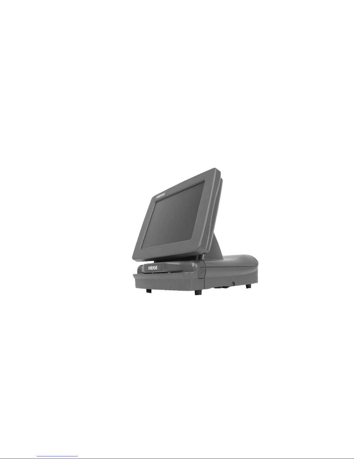
PC Workstation
Eclipse
Setup Guide
Copyright 2001, 2002, 2004
By MICROS Systems, Inc.
Columbia, Maryland USA
All Rights Reserved
Part Number 100016-113 (4th Edition)
Page 2

Declarations
Warranties
Trademarks
Although the best efforts are made to ensure that the
information contained in this manual is complete and correct,
MICROS Systems, Inc. makes no warranty of any kind with
regard to this material, inc l uding but not limited to the implied
warranties of marketa bility and fitness for a particular purpose .
Information in this manual is subject to change without notice .
MICROS Systems, Inc. shall not be liable fo r errors contained
herein or for incidental or consequential damages in connection
with the furnishing, performance, or use of this material.
MICROS is a registered trademark of MICROS Systems, Inc
Intel, Celeron, Pentium III, and MMX are registered trademarks of Intel
Corporation
Microsoft, Windows, Windows 95 Windows 98, Windows NT, Windows Sound
System, and Microsoft SQL Server are trademarks of Microsoft Corporation in
the United States of America and in other countries.
Adobe, Photoshop and FrameMaker are either registered trademarks or
trademarks of Adobe Systems, Incorporated in the United States of America
and/or other countries.
CorelDraw is a registered trademark of the Corel Corporation
Printing History
New editions of this manual incorporate new and changed
material since the previous edition. Minor corrections and
updates may be incorporated into reprints of the current edition
without changing the date or edition number.
1st Edition: May 2001
2nd Edition: September 2001
3rd Edition: March 2002
4th Edition: November 2004
ii
Page 3

Table of Contents
Declarations . . . . . . . . . . . . . . . . . . . . . . . . . . . . . . . . . . . . . . . . . . . . . . . . ii
Warranties . . . . . . . . . . . . . . . . . . . . . . . . . . . . . . . . . . . . . . . . . . . . . . . . . ii
Trademarks . . . . . . . . . . . . . . . . . . . . . . . . . . . . . . . . . . . . . . . . . . . . . . . . ii
Printing History . . . . . . . . . . . . . . . . . . . . . . . . . . . . . . . . . . . . . . . . . . . . . ii
Preface
Why Read This Manual? . . . . . . . . . . . . . . . . . . . . . . . . . . . . . . . . . . . . . . x
Purpose . . . . . . . . . . . . . . . . . . . . . . . . . . . . . . . . . . . . . . . . . . . . . . . . . . . . x
Who Should Use This Manual? . . . . . . . . . . . . . . . . . . . . . . . . . . . . . . . . . x
How This Manual is Organized . . . . . . . . . . . . . . . . . . . . . . . . . . . . . . . . xi
Notation Conventions . . . . . . . . . . . . . . . . . . . . . . . . . . . . . . . . . . . . . . . xii
Symbols . . . . . . . . . . . . . . . . . . . . . . . . . . . . . . . . . . . . . . . . . . . . . . . . . . xii
Document Design and Production . . . . . . . . . . . . . . . . . . . . . . . . . . . . . . xii
What Is The Eclipse Workstation?
Eclipse System Unit . . . . . . . . . . . . . . . . . . . . . . . . . . . . . . . . . . . . . . . . . . . 1-2
Eclipse LCD/Touchscreen Head . . . . . . . . . . . . . . . . . . . . . . . . . . . . . . . . . 1-3
12.1” LCD/Touchscreen Head . . . . . . . . . . . . . . . . . . . . . . . . . . . . . . . . 1-3
15” LCD/Touchscreen Head . . . . . . . . . . . . . . . . . . . . . . . . . . . . . . . . . 1-4
The Front Cover and Magnetic Card Reader . . . . . . . . . . . . . . . . . . . . . . . . 1-5
Features . . . . . . . . . . . . . . . . . . . . . . . . . . . . . . . . . . . . . . . . . . . . . . . . . . . . 1-6
Expansion Capabilities . . . . . . . . . . . . . . . . . . . . . . . . . . . . . . . . . . . . . 1-6
PCMCIA CardBus Slot . . . . . . . . . . . . . . . . . . . . . . . . . . . . . . . . . . . . . 1-6
Digital Visual Interface . . . . . . . . . . . . . . . . . . . . . . . . . . . . . . . . . . . . . 1-6
Sound . . . . . . . . . . . . . . . . . . . . . . . . . . . . . . . . . . . . . . . . . . . . . . . . . . . 1-6
Disk-On-Chip . . . . . . . . . . . . . . . . . . . . . . . . . . . . . . . . . . . . . . . . . . . . . 1-7
Accessories . . . . . . . . . . . . . . . . . . . . . . . . . . . . . . . . . . . . . . . . . . . . . . 1-7
Diagnostics Utilities . . . . . . . . . . . . . . . . . . . . . . . . . . . . . . . . . . . . . . . . 1-7
PCWS API . . . . . . . . . . . . . . . . . . . . . . . . . . . . . . . . . . . . . . . . . . . . . . . 1-7
Specifications . . . . . . . . . . . . . . . . . . . . . . . . . . . . . . . . . . . . . . . . . . . . . . . . 1-8
Approvals . . . . . . . . . . . . . . . . . . . . . . . . . . . . . . . . . . . . . . . . . . . . . . . . 1-9
Care and Handling . . . . . . . . . . . . . . . . . . . . . . . . . . . . . . . . . . . . . . . . . . . 1-11
Environmental Requirements . . . . . . . . . . . . . . . . . . . . . . . . . . . . . . . 1-11
Location . . . . . . . . . . . . . . . . . . . . . . . . . . . . . . . . . . . . . . . . . . . . . . . . 1-11
Foreign Materials . . . . . . . . . . . . . . . . . . . . . . . . . . . . . . . . . . . . . . . . . 1-11
Electrostatic Discharge (ESD) . . . . . . . . . . . . . . . . . . . . . . . . . . . . . . . 1-12
Temperature and Humidity . . . . . . . . . . . . . . . . . . . . . . . . . . . . . . . . . 1-12
Transporting the Workstation . . . . . . . . . . . . . . . . . . . . . . . . . . . . . . . 1-12
Cleaning The Eclipse Touchscreen and Cabinet . . . . . . . . . . . . . . . . . 1-12
LCD/Touchscreen . . . . . . . . . . . . . . . . . . . . . . . . . . . . . . . . . . . . . . . . 1-12
Cabinet . . . . . . . . . . . . . . . . . . . . . . . . . . . . . . . . . . . . . . . . . . . . . . . . . 1-12
iii
Page 4

Table of Contents
Magnetic Card Reader . . . . . . . . . . . . . . . . . . . . . . . . . . . . . . . . . . . . . 1-13
The I/O Panel . . . . . . . . . . . . . . . . . . . . . . . . . . . . . . . . . . . . . . . . . . . . . . . 1-14
P13 - Mic In - Line Out . . . . . . . . . . . . . . . . . . . . . . . . . . . . . . . . . . . . 1-14
The Modular Connector Block . . . . . . . . . . . . . . . . . . . . . . . . . . . . . . 1-15
Internal Speakers . . . . . . . . . . . . . . . . . . . . . . . . . . . . . . . . . . . . . . . . . 1-16
USB . . . . . . . . . . . . . . . . . . . . . . . . . . . . . . . . . . . . . . . . . . . . . . . . . . . 1-16
Mouse . . . . . . . . . . . . . . . . . . . . . . . . . . . . . . . . . . . . . . . . . . . . . . . . . . 1-16
Keyboard . . . . . . . . . . . . . . . . . . . . . . . . . . . . . . . . . . . . . . . . . . . . . . . 1-16
RS232 Serial, DB9 Connector (COM1) . . . . . . . . . . . . . . . . . . . . . . . 1-16
Parallel Port . . . . . . . . . . . . . . . . . . . . . . . . . . . . . . . . . . . . . . . . . . . . . 1-16
Digital Visual Interface (DVI) Connector . . . . . . . . . . . . . . . . . . . . . . 1-16
Cash Drawers 1 and 2 . . . . . . . . . . . . . . . . . . . . . . . . . . . . . . . . . . . . . 1-17
Remote Display . . . . . . . . . . . . . . . . . . . . . . . . . . . . . . . . . . . . . . . . . . 1-17
+24V Printer Power . . . . . . . . . . . . . . . . . . . . . . . . . . . . . . . . . . . . . . . 1-17
Auxiliary Power Connector . . . . . . . . . . . . . . . . . . . . . . . . . . . . . . . . . 1-17
Connecting Peripherals to the Eclipse . . . . . . . . . . . . . . . . . . . . . . . . . . . . 1-18
USB Floppy Disk Drive . . . . . . . . . . . . . . . . . . . . . . . . . . . . . . . . . . . . 1-18
USB Floppy Diskette Drive Letters . . . . . . . . . . . . . . . . . . . . . . . . . . . 1-18
Setting the USB Floppy Disk Drive to Boot the Workstation . . . . . . . 1-19
Connecting the Eclipse to a LAN . . . . . . . . . . . . . . . . . . . . . . . . . . . . 1-20
Operating the Eclipse . . . . . . . . . . . . . . . . . . . . . . . . . . . . . . . . . . . . . . . . . 1-21
Turning the Workstation On and Off . . . . . . . . . . . . . . . . . . . . . . . . . . 1-21
Using the Magnetic Card Reader . . . . . . . . . . . . . . . . . . . . . . . . . . . . . 1-22
Calibrating the Touchscreen . . . . . . . . . . . . . . . . . . . . . . . . . . . . . . . . 1-22
Using the 15” LCD/Touchscreen Head Controls . . . . . . . . . . . . . . . . 1-24
iv
BIOS Setup Utility
Starting the Phoenix Setup Utility/Checking the MICROS BIOS Version . 2-2
Requirements: . . . . . . . . . . . . . . . . . . . . . . . . . . . . . . . . . . . . . . . . . . . . 2-2
Procedure: . . . . . . . . . . . . . . . . . . . . . . . . . . . . . . . . . . . . . . . . . . . . . . . 2-2
Main . . . . . . . . . . . . . . . . . . . . . . . . . . . . . . . . . . . . . . . . . . . . . . . . . . . . .2-2
Advanced . . . . . . . . . . . . . . . . . . . . . . . . . . . . . . . . . . . . . . . . . . . . . . . . 2-2
Power . . . . . . . . . . . . . . . . . . . . . . . . . . . . . . . . . . . . . . . . . . . . . . . . . . . 2-2
Boot . . . . . . . . . . . . . . . . . . . . . . . . . . . . . . . . . . . . . . . . . . . . . . . . . . . . 2-3
Exit . . . . . . . . . . . . . . . . . . . . . . . . . . . . . . . . . . . . . . . . . . . . . . . . . . . . . 2-3
Keys Used During Setup . . . . . . . . . . . . . . . . . . . . . . . . . . . . . . . . . . . . 2-3
Main . . . . . . . . . . . . . . . . . . . . . . . . . . . . . . . . . . . . . . . . . . . . . . . . . . . . . . . 2-4
System Time: . . . . . . . . . . . . . . . . . . . . . . . . . . . . . . . . . . . . . . . . . . . . . 2-4
System Date: . . . . . . . . . . . . . . . . . . . . . . . . . . . . . . . . . . . . . . . . . . . . . 2-4
Legacy Diskette A: [Disabled] (BIOS Version 1.00.20 or later) . . . . . . 2-4
Primary Master [Displays Hard Disk Size in MB if Installed] . . . . . . . 2-4
Primary Slave . . . . . . . . . . . . . . . . . . . . . . . . . . . . . . . . . . . . . . . . . . . . . 2-6
Secondary Master . . . . . . . . . . . . . . . . . . . . . . . . . . . . . . . . . . . . . . . . . 2-6
Secondary Slave . . . . . . . . . . . . . . . . . . . . . . . . . . . . . . . . . . . . . . . . . . . 2-6
PC Beep Mute. . . . . . . . . . . . . . . . . . . . . . . . . . . . . . . . . . . . . . . . . . . . . 2-6
Page 5

Table Of Contents
After Power Failure (BIOS Version 1.00.20 or later) . . . . . . . . . . . . . . 2-6
LAN Boot Function . . . . . . . . . . . . . . . . . . . . . . . . . . . . . . . . . . . . . . . . 2-6
System Memory . . . . . . . . . . . . . . . . . . . . . . . . . . . . . . . . . . . . . . . . . . . 2-7
Extended Memory . . . . . . . . . . . . . . . . . . . . . . . . . . . . . . . . . . . . . . . . . 2-7
Advanced . . . . . . . . . . . . . . . . . . . . . . . . . . . . . . . . . . . . . . . . . . . . . . . . . . . 2-8
Installed O/S . . . . . . . . . . . . . . . . . . . . . . . . . . . . . . . . . . . . . . . . . . . . . . 2-8
Reset Configuration Data . . . . . . . . . . . . . . . . . . . . . . . . . . . . . . . . . . . . 2-8
PS/2 Mouse (BIOS Version 1.00.20 or later) . . . . . . . . . . . . . . . . . . . . . 2-8
IO Device Configuration -> . . . . . . . . . . . . . . . . . . . . . . . . . . . . . . . . . . 2-9
Local Bus IDE Adapter . . . . . . . . . . . . . . . . . . . . . . . . . . . . . . . . . . . . 2-11
Advanced Chipset Control -> . . . . . . . . . . . . . . . . . . . . . . . . . . . . . . . . 2-11
Power . . . . . . . . . . . . . . . . . . . . . . . . . . . . . . . . . . . . . . . . . . . . . . . . . . . . . 2-12
Power Savings: . . . . . . . . . . . . . . . . . . . . . . . . . . . . . . . . . . . . . . . . . . . 2-12
Resume On Time: . . . . . . . . . . . . . . . . . . . . . . . . . . . . . . . . . . . . . . . . . 2-12
Resume Time: . . . . . . . . . . . . . . . . . . . . . . . . . . . . . . . . . . . . . . . . . . . . 2-12
Resume On Modem Ring:. . . . . . . . . . . . . . . . . . . . . . . . . . . . . . . . . . . 2-12
Boot . . . . . . . . . . . . . . . . . . . . . . . . . . . . . . . . . . . . . . . . . . . . . . . . . . . . . . 2-13
Exit . . . . . . . . . . . . . . . . . . . . . . . . . . . . . . . . . . . . . . . . . . . . . . . . . . . . . . . 2-15
Exit Saving Changes . . . . . . . . . . . . . . . . . . . . . . . . . . . . . . . . . . . . . . . 2-15
Exit Discarding Changes . . . . . . . . . . . . . . . . . . . . . . . . . . . . . . . . . . . 2-15
Load Setup Defaults . . . . . . . . . . . . . . . . . . . . . . . . . . . . . . . . . . . . . . . 2-15
Discard Changes . . . . . . . . . . . . . . . . . . . . . . . . . . . . . . . . . . . . . . . . . . 2-15
Save Changes . . . . . . . . . . . . . . . . . . . . . . . . . . . . . . . . . . . . . . . . . . . . 2-15
PCWS Eclipse Hardware Configuration
Disassembling the Eclipse . . . . . . . . . . . . . . . . . . . . . . . . . . . . . . . . . . . . . . 3-2
What’s Inside? . . . . . . . . . . . . . . . . . . . . . . . . . . . . . . . . . . . . . . . . . . . . . . . 3-8
System Board Devices . . . . . . . . . . . . . . . . . . . . . . . . . . . . . . . . . . . . . . 3-8
STK3 - Socket 370 Processor Socket . . . . . . . . . . . . . . . . . . . . . . . . . . . 3-8
Intel© i810 Chipset . . . . . . . . . . . . . . . . . . . . . . . . . . . . . . . . . . . . . . . . 3-9
DIMM Sockets . . . . . . . . . . . . . . . . . . . . . . . . . . . . . . . . . . . . . . . . . . . 3-11
Silicon Image Panel Link Transmitter. . . . . . . . . . . . . . . . . . . . . . . . . . 3-11
Altera POS and IO Controller . . . . . . . . . . . . . . . . . . . . . . . . . . . . . . . 3-11
IT8702F-A Super IO Controller . . . . . . . . . . . . . . . . . . . . . . . . . . . . . . 3-11
Texas Instruments PC1211 PCMCIA Controller . . . . . . . . . . . . . . . . . 3-12
Realtek RTL8139B 10/100 Ethernet Controller . . . . . . . . . . . . . . . . . . 3-12
IT8888F PCI-to-ISA Bridge . . . . . . . . . . . . . . . . . . . . . . . . . . . . . . . . . 3-12
Disk On Chip . . . . . . . . . . . . . . . . . . . . . . . . . . . . . . . . . . . . . . . . . . . . 3-12
AC97 Audio . . . . . . . . . . . . . . . . . . . . . . . . . . . . . . . . . . . . . . . . . . . . . 3-12
System Board Connectors . . . . . . . . . . . . . . . . . . . . . . . . . . . . . . . . . . 3-13
Remove/Replace the Customer Display . . . . . . . . . . . . . . . . . . . . . . . . . . . 3-14
Remove/Replace Power Supply . . . . . . . . . . . . . . . . . . . . . . . . . . . . . . . . 3-16
Remove/Replace the Hard Disk . . . . . . . . . . . . . . . . . . . . . . . . . . . . . . . . . 3-18
Remove/Replace DIMMs . . . . . . . . . . . . . . . . . . . . . . . . . . . . . . . . . . . . . . 3-20
Recommended DIMMs . . . . . . . . . . . . . . . . . . . . . . . . . . . . . . . . . . . . 3-20
v
Page 6

Table of Contents
Purchasing DIMMs . . . . . . . . . . . . . . . . . . . . . . . . . . . . . . . . . . . . . . . 3-20
Configuring DIMMs . . . . . . . . . . . . . . . . . . . . . . . . . . . . . . . . . . . . . . 3-21
Installing DIMMs . . . . . . . . . . . . . . . . . . . . . . . . . . . . . . . . . . . . . . . . 3-22
Remove a DIMM . . . . . . . . . . . . . . . . . . . . . . . . . . . . . . . . . . . . . . . . . 3-23
Remove/Replace the System Processor . . . . . . . . . . . . . . . . . . . . . . . . . . . 3-24
The Celeron vs. the Pentium III Processor . . . . . . . . . . . . . . . . . . . . . 3-24
Installing a PCMCIA Card . . . . . . . . . . . . . . . . . . . . . . . . . . . . . . . . . . . . 3-29
Installing a Disk On Chip . . . . . . . . . . . . . . . . . . . . . . . . . . . . . . . . . . . . . 3-32
Re-assembling the Eclipse . . . . . . . . . . . . . . . . . . . . . . . . . . . . . . . . . . . . . 3-36
Eclipse LCD/Touchscreen Head Configuration
Disassembling the LCD/Touchscreen Head . . . . . . . . . . . . . . . . . . . . . . . . 4-2
Removing the Rear Cover and Interface Board Shield. . . . . . . . . . . . . . 4-2
The LCD/Touchscreen Board . . . . . . . . . . . . . . . . . . . . . . . . . . . . . . . . . . . 4-4
LCD/Touchscreen Board -001 TFT LCD - MicroTouch TSC) . . . . . . . 4-5
LCD/Touchscreen Board -001 - Connectors and Jumpers . . . . . . . . . . 4-6
LCD/Touchscreen Board -002 (DSTN LCD - MicroTouch TSC) . . . . 4-7
LCD/Touchscreen Board -002 - Connectors and Jumpers. . . . . . . . . . . 4-8
LCD/Touchscreen Board -003 (TFT LCD - Hampshire TSC) . . . . . . . 4-9
LCD/Touchscreen Board -003 - Connectors and Jumpers . . . . . . . . . 4-10
LCD Interface Description (-001, -002 ad -003 Boards) . . . . . . . . . . . . . . 4-11
LCD Panels . . . . . . . . . . . . . . . . . . . . . . . . . . . . . . . . . . . . . . . . . . . . . 4-11
Touchscreen Interface . . . . . . . . . . . . . . . . . . . . . . . . . . . . . . . . . . . . . . . . 4-12
-001 and -002 LCD/Touchscreen Interface Boards . . . . . . . . . . . . . . . 4-12
Touchscreen Jumper Settings . . . . . . . . . . . . . . . . . . . . . . . . . . . . . . . . 4-12
-003 LCD/Touchscreen Interface Board . . . . . . . . . . . . . . . . . . . . . . . 4-13
LCD Backlight Inverter/On Board Voltage Regulators . . . . . . . . . . . . . . . 4-14
+3.3V and +5.0V On-Board Regulators . . . . . . . . . . . . . . . . . . . . . . . 4-15
Installing the Interface Board Shield and Back Cover . . . . . . . . . . . . . . . 4-16
PCWS Eclipse Diagnostics
Basic Troubleshooting . . . . . . . . . . . . . . . . . . . . . . . . . . . . . . . . . . . . . . . . . 5-2
Front Panel LEDs . . . . . . . . . . . . . . . . . . . . . . . . . . . . . . . . . . . . . . . . . . . . . 5-5
FD (Full Duplex), Link, and Network Active . . . . . . . . . . . . . . . . . . . . 5-5
Disk LED . . . . . . . . . . . . . . . . . . . . . . . . . . . . . . . . . . . . . . . . . . . . . . . . 5-5
Power LED . . . . . . . . . . . . . . . . . . . . . . . . . . . . . . . . . . . . . . . . . . . . . . 5-5
POST Error Beep Codes . . . . . . . . . . . . . . . . . . . . . . . . . . . . . . . . . . . . . . . 5-6
Equipment Dimensions
PCWS Eclipse Workstation . . . . . . . . . . . . . . . . . . . . . . . . . . . . . . . . . . . . . A-2
PCWS Eclipse Workstation with 15” LCD/Touchscreen Head . . . . . . . . . A-3
PCWS Remote Pole Display . . . . . . . . . . . . . . . . . . . . . . . . . . . . . . . . . . . . A-4
Cash Drawer . . . . . . . . . . . . . . . . . . . . . . . . . . . . . . . . . . . . . . . . . . . . . . . . A-5
vi
Page 7

Table Of Contents
Cash Drawer, Low Profile . . . . . . . . . . . . . . . . . . . . . . . . . . . . . . . . . . . . . .A-6
Connector and Cable Diagrams
Front Panel Connectors . . . . . . . . . . . . . . . . . . . . . . . . . . . . . . . . . . . . . . . . .B-2
Modular Connector Block . . . . . . . . . . . . . . . . . . . . . . . . . . . . . . . . . . .B-2
LCC/IDN . . . . . . . . . . . . . . . . . . . . . . . . . . . . . . . . . . . . . . . . . . . . . . . .B-2
LCC(-) . . . . . . . . . . . . . . . . . . . . . . . . . . . . . . . . . . . . . . . . . . . . . . . . . .B-3
RS232 . . . . . . . . . . . . . . . . . . . . . . . . . . . . . . . . . . . . . . . . . . . . . . . . . . .B-3
Modular COM Ports 2, 3, 5 and 6 . . . . . . . . . . . . . . . . . . . . . . . . . . . . .B-4
10/100 Ethernet Connector . . . . . . . . . . . . . . . . . . . . . . . . . . . . . . . . . . .B-4
RS232 Connector . . . . . . . . . . . . . . . . . . . . . . . . . . . . . . . . . . . . . . . . . .B-5
USB Connectors . . . . . . . . . . . . . . . . . . . . . . . . . . . . . . . . . . . . . . . . . . .B-5
Digital Visual Interface (DVI) Connector . . . . . . . . . . . . . . . . . . . . . . .B-6
Parallel Port Connector . . . . . . . . . . . . . . . . . . . . . . . . . . . . . . . . . . . . . .B-7
Cash Drawer 1 and 2 Connectors . . . . . . . . . . . . . . . . . . . . . . . . . . . . . .B-8
PS2 Mouse/Keyboard Connectors . . . . . . . . . . . . . . . . . . . . . . . . . . . . .B-8
Remote Customer Display Connector . . . . . . . . . . . . . . . . . . . . . . . . . .B-9
Front Panel Power Connectors . . . . . . . . . . . . . . . . . . . . . . . . . . . . . . . .B-9
System Board Connectors . . . . . . . . . . . . . . . . . . . . . . . . . . . . . . . . . . . . .B-10
ATX Power Connector . . . . . . . . . . . . . . . . . . . . . . . . . . . . . . . . . . . . .B-10
Power Switch Connector . . . . . . . . . . . . . . . . . . . . . . . . . . . . . . . . . . .B-11
Hook-up Cables . . . . . . . . . . . . . . . . . . . . . . . . . . . . . . . . . . . . . . . . . . . . .B-12
LCC/RS232 Port . . . . . . . . . . . . . . . . . . . . . . . . . . . . . . . . . . . . . . . . . .B-12
COM5 and COM6 Modular Connectors. . . . . . . . . . . . . . . . . . . . . . . .B-13
Ethernet . . . . . . . . . . . . . . . . . . . . . . . . . . . . . . . . . . . . . . . . . . . . . . . . .B-14
Cross-over Pinning . . . . . . . . . . . . . . . . . . . . . . . . . . . . . . . . . . . . . . . .B-15
8-Pin to 6-Pin Hook-up RS422 Cable (300319-001) . . . . . . . . . . . . . .B-16
Cash Drawer Extension Cable . . . . . . . . . . . . . . . . . . . . . . . . . . . . . . .B-17
vii
Page 8

Table of Contents
viii
Page 9

Preface
In this preface, you’ll find information about this manual. Refer to the
preface if you have questions about the organization, conventions, or
contents of this manual.
In this section
Why Read This Manual?.......................... .. .. ....................... ......... x
How This Man ua l Is Organized ........ ................ ............... ..........xi
Notation Conventions ................................................................xii
PCWS Eclipse Setup Guide ix
Page 10

Preface
Why Read This Manual?
Why Read This Manual?
Purpose
This guide is intended for those who will be setting up and installing the
PCWS Ultra h ardware and as such is not specific to a particular soft ware
application. To use the PCWS with a specific application, consult the
Related Manuals section listed below.
Who Should Use This Manual?
This manual is intended for qualified service personnel who have
experience with upgrading and configuration of personal computer based
systems.
x PCWS Eclipse Setup Guide
Page 11
How This Manual is Organized
This manual is divided into five chapters, briefly discussed below.
Chapter 1 describes each of the Eclipse components and shows how to
assemble them into a comple te workstation. The chapter also provides
specifications, care and handling instructions, and information on how to
connect peripherals to the Front I/O Panel.
Chapter 2 describes how to use the Phoenix BIOS Setup Utility to
configure the Eclipse hardware.
Chapter 3 covers the Eclipse system unit hardware configuration. Topics
include how to remove the cover , iden tify the majo r components, an d how
to upgrade or configure such items as the main memory, processor, and
hard disk, or to install the optional internal customer display.
Chapter 4 covers the Eclipse LCD\Touchscreen Head configuration.
Topics include how to remove the cover, identify individual components,
and set configuration jumpers for the LCD panel and touchscreen
interface.
Preface
How This Manual is Organized
Chapter 5 provides basic troubleshooting data in the form of BIOS error
messages and beep codes.
A Reference section consisting of Equipment Dimensions, FCC/DOC
Statement, and Conne ctor/ Cable Diag rams can be found at th e end of this
manual.
SHOCK HAZARD
No user serviceable pa rts inside.
Refer servicing to qualified personnel.
PCWS Eclipse Setup Guide xi
Page 12
Preface
Notation Conventions
Notation Conventions
Symbols
NOTE
This symbol brings special attention to a related item.
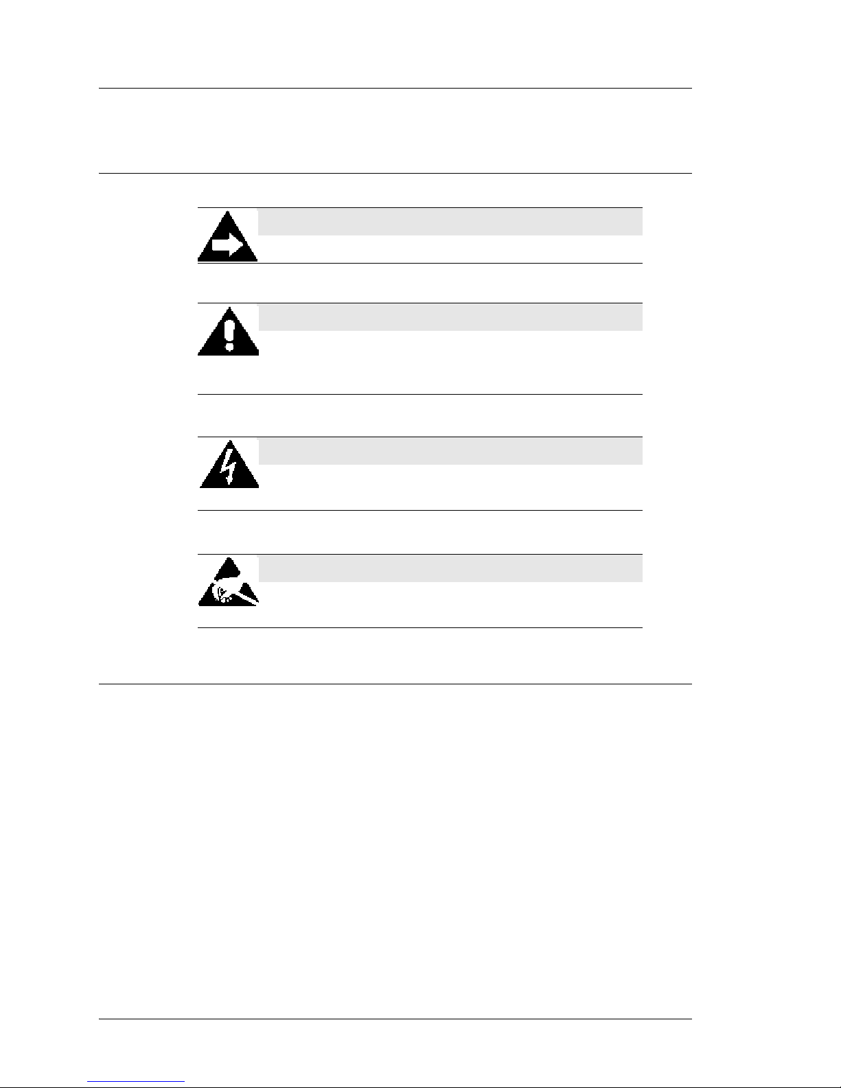
WARNING
This symbol indicates that specific handling instructions or
procedures are required to prevent damage to the hardware or
loss of data.
SHOCK HAZARD
This symbol calls attention to a potential hazard that requires
correct procedures in order to avoid personal injury.
STATIC SENSITIVE DEVICES
This symbol indicates that specific ESD handling procedures
are required.
Document Design and Production
Desktop Publishing: Adobe FrameMaker.
Imaging: Nikon Coolpix 990.
Image processing: Adobe Photosh op, Paint Shop Pro.
Line drawings: Corel Draw!
xii PCWS Eclipse Setup Guide
Page 13

Chapter 1
What Is The Eclipse Workstation?
In this chapter
The System ...................................................................................................1-2
Features........................................................................................................1-6
Specifications............................................................................................... 1-8
The I/O Panel............................................................................................. 1-14
Connecting Peripherals to the Eclipse....................................................... 1-18
Operating the Eclipse................................................................................. 1-21
PCWS Eclipse Setup Guide 1-1
Page 14
What Is The Eclipse Workstation?
The System
The System
The following section describes the PCWS Eclipse Workstation and components. The
Eclipse will be available with two LCD/Touchscreen Head selections.
Eclipse System Unit
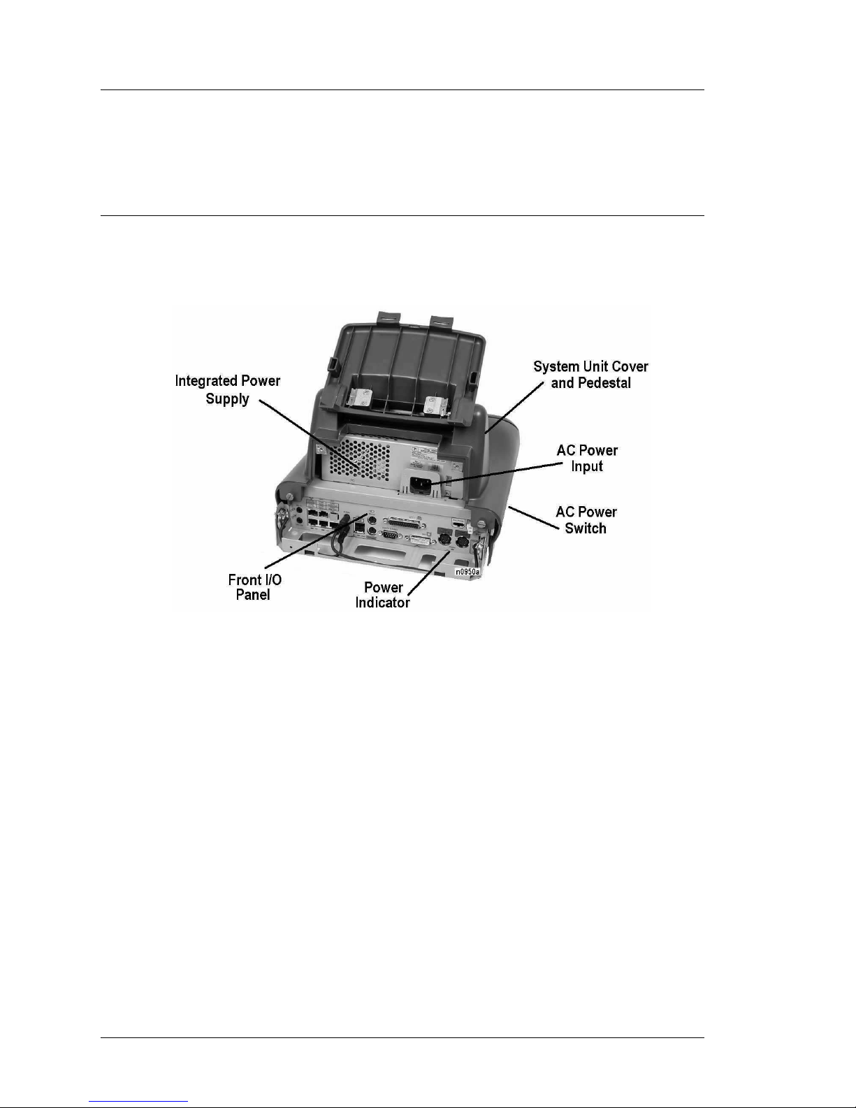
The Eclipse System Uni t, shown in Fig ure 1 -1, con si sts of a plastic co ver a nd pede stal
which fits over a metal chassis.
Figure 1-1: The Eclipse System Unit
The system unit contains the power supply, system board, and optionally, a single
desktop style IDE hard disk and 2x20 customer display. All input/output connectors
are accessible from the front of the unit. See Chapter 3 for more information about
hardware configuration.
The AC power switch is located under the system unit on the right side of the
workstation.
The integrated power supply replaces the external AC power brick used in previous
PCWS models. In addition, a +24V power connector mounted to the front panel
allows a single Epson U220 or TMT-88 Roll Printer to be powered from the Eclipse,
eliminating a second power brick.
1-2 PCWS Eclipse Setup Guide
Page 15
Eclipse LCD/Touchscreen Head
The PCWS Eclipse is now available with two display configurations. The standard
display is based on a 12.1” TFT LCD Panel, and a new optional display is available,
based on a 15” TFT LCD Panel. Each component is detailed below.
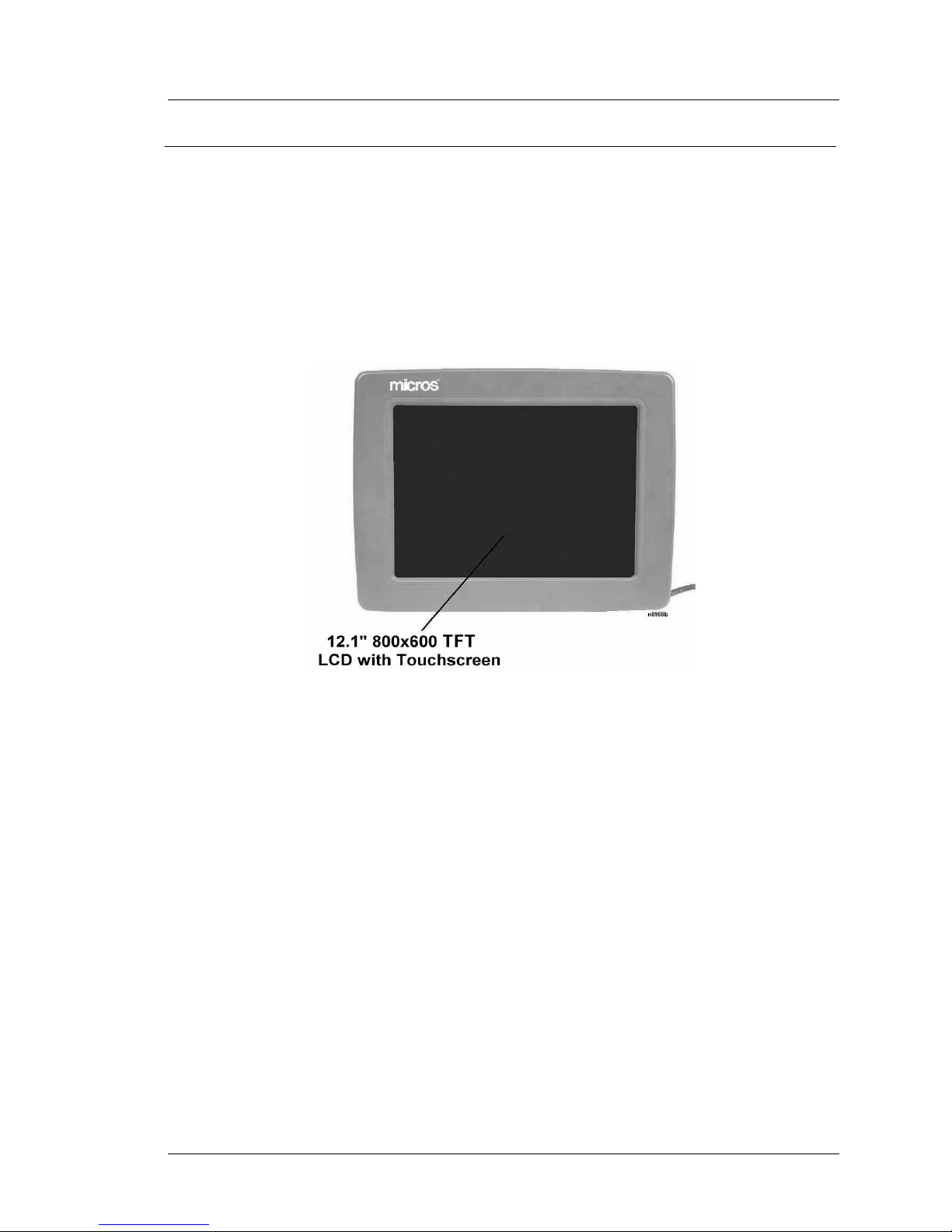
The 12.1” LCD/Touchscreen Head
The 12.1” LCD/Touchscreen Head, shown in Figure 1-2, contains an 800x600 TFT
LCD panel coupled to a Elo TouchSystems 5-wire resistive touchscreen.
What Is The Eclipse Workstation?
The System
Figure 1-2: The Eclipse 12.1” LCD/Touchscreen Head
The 12.1” LCD/Touchscreen Head is modular, attached to the pedestal with
thumbscrews.
The Eclipse front pane l DVI connector supplies all LCD, touchscreen, backlight
control and data signals as well as +12V to the LCD/Touchscreen Head. Within the
head, a single circuit board controls the LCD, Touchscreen, and Contrast/Backlight
interface circuitry.
See Chapter 4 for more information about the 12.1” LCD/Touchscreen head
configuration.
PCWS Eclipse Setup Guide 1-3
Page 16
What Is The Eclipse Workstation?
The System
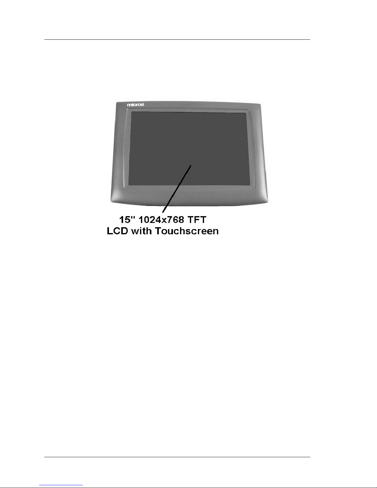
The 15” LCD/Touchscreen Head
The optional 15” LCD/Touchscreen Head, shown below, contains a 1024x768 TFT
LCD Panel coupled to a 5-wire resistive touchscreen.
Figure 1-3: The Eclipse 15” LCD/Touchscreen Head
Due for release in November 2004, the optional 15” LCD/Touchscreen head is a
modified version of a retail ELO Touchsystems 15” LCD Monitor/Touchscreen
combination. It is fastened directly to the pedestal hinge.
The Eclipse front panel DVI connector supplies all LCD, touchscreen, backlight
control and data signals as well as +12V to the LCD/Touchscreen Head. Firmware
modifications allow this display to emulate the 12” LCD/Touchscreen at the API
level. The POS Application controls the backlight on/off and brightness in the same
manner as the 12.1” LCD/Touchscreen head.
The right side of the display housing includes several controls to manipulate the On
Screen Display (OSD) function and power on/off button. Refer to page 1-24 for more
information.
Internally, the display consists of a Video Inte rface Board, Touchscree n Interface
Board, Power Supply Board, a nd Backl ight Inv erter Board along with a 15” TFT LCD
Panel and 5-wire resistive touch panel.
1-4 PCWS Eclipse Setup Guide
Page 17
What Is The Eclipse Workstation?
The System
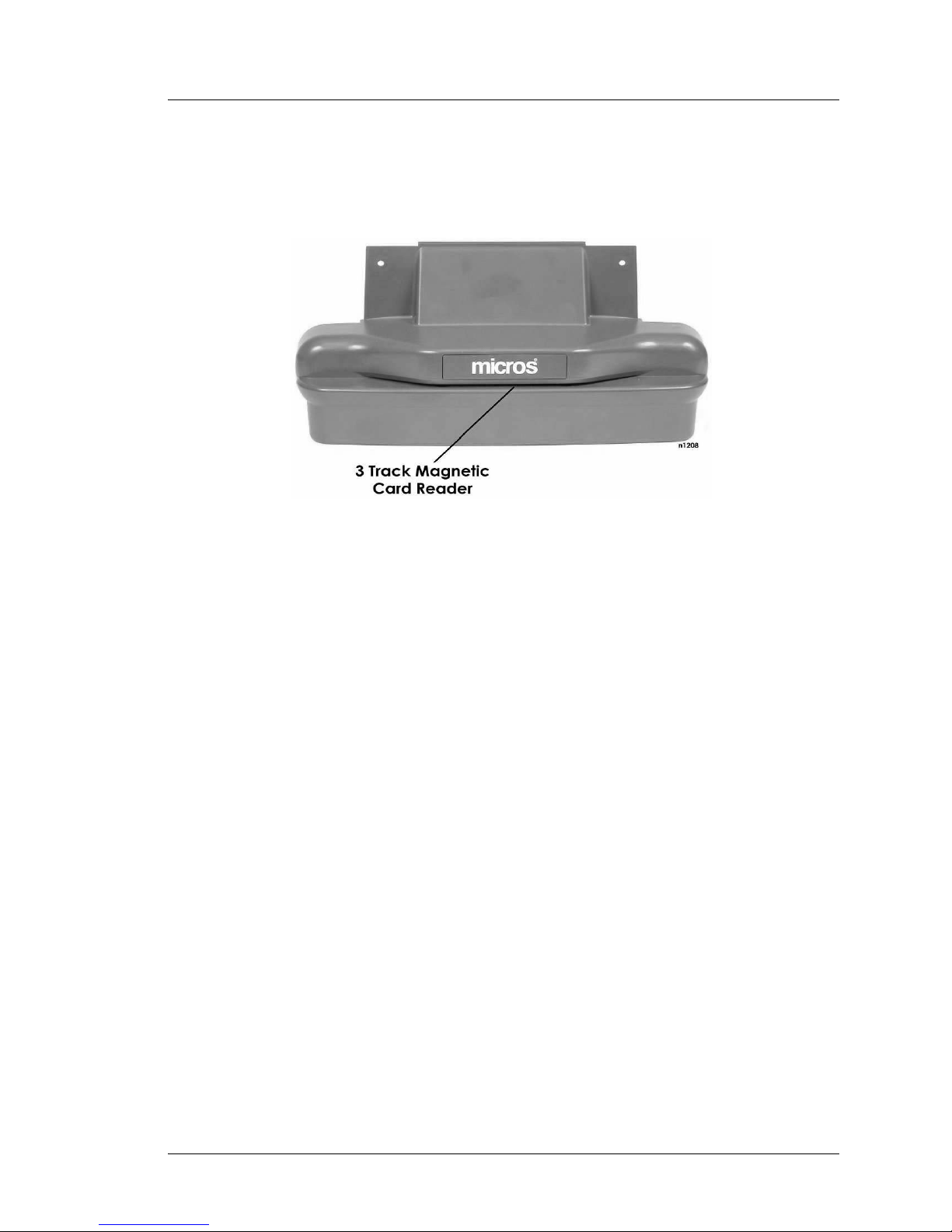
The Front Cover and Magnetic Card Reader
Figure 1-4 shows the Fr ont Cove r or MCR Unit incl uding a stand ard 3- track magne tic
card reader .
Figure 1-4: The Eclipse Front Cover
The magnetic card reader can be easily removed and replaced in just a few minutes.
The entire reader assembly attaches to the Eclipse with a modular connector, further
allowing the unit to be quickly and easily replaced.
PCWS Eclipse Setup Guide 1-5
Page 18

What Is The Eclipse Workstation?
Features
Features
Expansion Capabilities
The Eclipse does not contain ISA or PCI slots. Expansion takes the form of a Type II
PCMCIA Cardbus Slot, USB port(s), and three available serial ports.
PCMCIA CardBus Slot
The Eclipse Workstation includes a single Type II 32-bit PCMCIA CardBus Slot.
Established in 1995 by the Personal Computer Memory Card International
Association (PCMCIA), t he CardBus PC Car d is a 32- bit version o f the ori ginal 16- bit
PC Card standard, offering higher levels of performance.
Part of the PC Card family, a CardBus PC Card conforms to an established physical
form factor, providing a compact, rugged card that can be inserted completely within
its host workstation without any external cabling (except when the card must be
attached to a LAN, telephone line, or a wireless antenna).
Digital Visual Interface
Sound
T o dr ive the LCD panel a Digit al Visual Interface (DVI) is emplo yed. Th is hig h speed
digital connection replaces the conventional analog RGB interface to CRT monitors.
The DVI interface allows the display content to re main in a lossless digital format
from the system board graphics controller to the LCD panel. DVI offers the following
features:
• Display technology independence
• Plug and Play. If you swap a DSTN display for a TFT display on the Eclipse, this
will be detected by the Display Data Channel Interface.
• Display contrast and backlight control for DSTN panels.
• Digital and Analog support through a single connector, using a cable specific to
each application. (Analog cable currently not available).
DVI uses a Transition Minimized Differential Signalling (TMDS) protocol and
encoding algorit hm f or t he base electrical interconnection. These signals are routed to
the LCD/Touchscreen Head where they are decoded into pixel data compatible with
the LCD.
The Intel 810 Chipset supports the Audio Codec ‘97 digital audio component
specification which consists of a 2 device audio solution comprised of a digital
component, (the ICH) and a high quality analog component (the AD1819A) that
includes a Digital To Analog Converter (DAC) and Analog to Digital Converter
(ADC), mixer, and IO.
The Eclipse supports the following sound capabilities.
• PCI 2.1 bus master interface and AC-link controller
1-6 PCWS Eclipse Setup Guide
Page 19

• Audio playback through internal or external speakers
• Audio capture from the microphone input.
• Red Book Audio CD
• Headset and Speaker phone for DSVD modems
• Hardware MIDI synthesis
• Sound Max Audio Drivers support the Analog Devices Codec.
Built-in Speakers
The Eclipse includes a pair of water resistant speakers mounted on each side of the
front connector panel.
Disk-On-Chip
The Eclipse system board supports the M-Systems Disk On Chip (DOC) device. A
Disk On Chip consists of a block of Flash EPROM, residing behind firmware that
when supported by the workstation’s BIOS, looks like a bootable or non-bootable
removable drive. It can be configured to boot the workstation through CMOS Setup.
The Eclipse w ill ship with a 32-PIN DIP s ocket to allow field installation of the
device. Details on installing and configuring the DOC can be found in Chapter 3.
What Is The Eclipse Workstation?
Features
Accessories
The following accessories will be supported for the Eclipse. The External Floppy
Diskette used by previous workstation models is not supported.
• USB Floppy
• USB and Parallel Port CD-ROM Drive
• PC Keyboard
Diagnostics Utilities
An updated version of DEMODIAG is supplied on the OS images. It supports all of
the Eclipse features including the 3-track card reader.
PCWS API
The PCWS Application Programming Interface (API) is a set of services that resides
between application software and the operating system and the unique POS hardware
on the system board. This allows POS applications such as 3700 to use a standard set
of API calls to access such POS features as LCD contrast, reading magnetic stripe
data, and opening a cash drawer or reading it’s status.
PCWS Eclipse Setup Guide 1-7
Page 20

What Is The Eclipse Workstation?
Specifications
Specifications
The PCWS Eclipse workstation conform s to the following specifications.
Specification Parameters
Processors Celeron C850MHz or Pentium III 1GHz
Processor Socket Socket 370
Cache Celeron = 128K L2 cache, Pentium III = 256K
Display(s) 12.1” TFT LCD, Optional 15” TFT LCD
Touchscreen Elo 12.1” or 15” five-wire resistive, 100
Backlight(s) Can be set to one of three intensity levels
L2 cache,
thousand points-per-inch resolution rated at a
screen life of over 35 million touches.
through the API
DVI/VGA Interface The Front Panel DVI Connector supports
either the LCD Head or standard CRT/LCD
with a custom wired cable.
BIOS Phoenix 4.0 BIOS Plug ‘n Play DMI 2.0
compliant in flash EPROM, includes updated
LAN boot software to support diskless
workstations.
BIOS Setup Utility Configures system time and data, hard drive
parameters, assigns COM and LPT port
resources, and the boot device sequence.
Real Time Clock Time-of-day clock: 100-year calendar with
alarm features and century roll-over, includes
256 bytes of battery backed CMOS RAM,
reserved for BIOS use.
Memory Two DIMM sockets support 64 MB to 512 MB
Max (256M Per Slot) of PC100 SDRAM
(+3.3V, Unbuffered)
Mag Stripe Reader 3-Track ABA compatible, operates in
MAGTEK and Special modes.
Customer Displays Optional 2 x 20 character internal customer
display mounts to rear of system unit and or
optional pole mount 2 x 40 character remote
pole display
USB Ports Two UHCI 1.1 compliant USB ports
LAN Interface On-board 10/100 Ethernet. Includes MBA
1-8 PCWS Eclipse Setup Guide
UNDI Version 4.3 Boot ROM
Page 21

What Is The Eclipse Workstation?
Specifications
Specification Parameters
Parallel Port Supports centronics, EPP, and ECP standards
Input Power 200W Max
Input Voltage Universal input 90-254VAC 47-63Hz.
Input Current 0.9A to 1.2A @ 115V
+24VDC Printer Power Out +24VDC @ 4A Max (Littlefuse R251004)
Aux Power Out +5VDC @ 5A Max (Littlefuse RS251005)
+12VDC @ 5A Max (Littlefuse RS251005)
Storage Temperature -25°C (-13°F) to 85°C (185°F)
Operating Temperature Pentium 1 GHz = 5°C (40°F) to 40°C (104°F)
Celeron C850Mhz = 5°C (40°F) to 45°C
(113°F)
90% relative humidity max
Weight 18lb /w Hard Disk and Customer Display
Case Material ABS Plastic
Physical Dimensions See Appendix A
Approvals
The Eclipse Workstation meets the following safety and environmental certifications.
Certification Number Comments
Underwriters Laboratory, Inc., Standard for
Safety of Information Technology Equipment
CE European Union Declaration of
Conformity, Electromagnetic Compatibility
Directive
FCC Rules for Class A computing devices Part 15
Canadian Standards Association Standard 22.2
Test and Declaratio n of Conf ormit y for CE
Mark of European Safety Approval
UL-1950
89/336/EEC
EN60950
Test and Declaratio n of Conf ormit y for CE
Mark of European EMI Approval
Test and Declaratio n of Conf ormit y for CE
Mark of European ESD, RF, and Transient
Susceptibility
PCWS Eclipse Setup Guide 1-9
EN55022
EN50082-1
Page 22

What Is The Eclipse Workstation?
Specifications
Certification Number Comments
International Electrotechnical Commission,
Electromagnetic Compatibility for
Industrial-Process Measurement and Control
Equipment
IEC801-2 8kV
IEC801-3 27-500MHz, 3V/cm
(UNMOD)
IEC801-4 0.5kV SIGNAL LINES,
1.0kV AC Mains
1-10 PCWS Eclipse Setup Guide
Page 23
Care and Handling
The following pages offer tips for placing the workstation in an environmentally safe
location and tips for cleaning the workstation cabinet and touchscreen.
Environmental Requirements
To ensure proper operation of the equipment, consider the following guidelines for
placement of the Eclipse PC Workstation.
Dimensional data for the workstation and peripheral printers can be found in
Appendix A of this manual. Before you decide on the space each device should
occupy, take measurements and compare them to ours.
Location
Tile is the recommended floor surface for areas surrounding the workstation. If the
floor cover ing adjacent to the equipment is carpeted, an anti-static grade is
recommended. If the carpeting surrounding the area containing the equipment is not
composed of anti-static material, the use of static-discharge mats should be
considered. The recommended type of anti-static mat is one that incorporates a
grounding clip with a cable to provide a discharge path to ground.
What Is The Eclipse Workstation?
Care and Handling
Foreign Materials
WARNING:
Do not use sharp objects such as a pen or pencil to press keys
on the touchscreen as this could damage the sensing layer.
Liquid spillage can cause dama ge to the cir cuit s in the unit . Do
not place the equipment near food preparation areas, dish
racks, or water stations. The Eclipse LCD head includes a
gasket seal around the touchscreen which may afford some
protection from liquid spillage.
If any type of liquid is spilled onto the touchscreen or on the
top of the unit, turn off power as quickly as possible by
removing the AC power cord from the wall plate. Do not
reconnect the AC power cord to an outlet until it has been
determined that no spillage remains inside the un it.
PCWS Eclipse Setup Guide 1-11
Page 24

What Is The Eclipse Workstation?
Care and Handling
Electrostatic Discharge (ESD)
The occurrence of electrostatic discharge (ESD) usually takes the form of a discharge
from the operator’s hand to cash drawers, the workstation, the magnetic stripe card
reader or other peripherals connected to the workstation.
ESD is more common in dry climates during the winter, and less common in moist
climates. The Eclipse has excellent built-in immunity to ESD in most environments.
However, tile or anti-static carpet should still be employed in areas near the
workstation.
Temperature and Humidity
The PCWS Eclipse operating temperature is between 40°F and 113°F (5°C to 45°C),
if the Celeron C850 MHz processor is installed.
The PCWS Eclipse operating temperature is between 40°F and 104°F (5°C to 40°C),
if the Penti um III 1GHz pr ocessor is ins talled.
A constant humidity between 40% and 90% is required for proper operation of the
equipment.
Before applying power to the workstation, ensure that its temperature is w ithin 15°F
(8°C) of room temperature to prevent damage to its internal circuitry.
Transporting the Workstation
When a hard disk is installed, always power down the Eclipse workstation before
transporting it, even if you are just moving it across your work surface. High density
hard drives are more susceptible to damage if subjected to a sudden physical shock
while they are operating, especially if the heads happen to be reading or writing to the
disk surface. Powering off the workstation parks the hard disk heads, allowing you to
move it without risking damage.
Cleaning The Eclipse Touchscreen and Cabinet
Instructions for cl eaning the Eclipse Cabinet and LCD/Touchscreen are described
below.
SHOCK HAZARD
Always turn off the workstation before cleaning or performing
any preventive maintenance.
LCD/Touchscreen
You can clean the touchscreen wit h any common household gl ass clean er applie d with
a clean cotton cloth. Always spray the cloth with the cleaner and then use the cloth to
clean the touchscreen.
Cabinet
Always use a chamois or clean lint-free cloth to clean the cabinet and touchscreen
surface. Do not use chemical, alcohol, or petroleum based cleaners that are not
recommended for plastics.
1-12 PCWS Eclipse Setup Guide
Page 25

What Is The Eclipse Workstation?
Care and Handling
Magnetic Card Reader
Depending on how much they are used, magnetic card readers may require periodic
cleaning. Cleaning kits are available from a variety of sources. Be sure to follow the
instructions supplied with the cleaning kits.
PCWS Eclipse Setup Guide 1-13
Page 26
What Is The Eclipse Workstation?
The I/O Panel
The I/O Panel
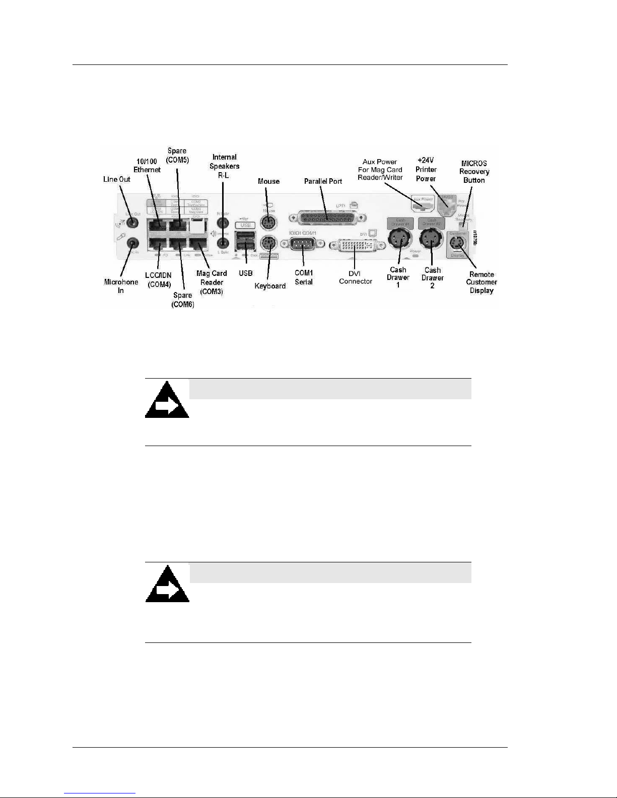
Figure 1-5, below points out each connector on the Eclipse IO Panel.
Figure 1-5: The Eclipse I/O Panel
NOTICE:
This equipment shall only be connected to a public
telecommunications network by an external device approved
for use in the country in wh ich the equipment is install ed.
Working from left to right, descriptions for each conn ector follow s.
P13 - Mic In - Line Out
The Microphone input jack allows you to connect a microphone to the Eclipse and
record sound clips.
The Line Out jack is capable of driving most external powered speakers.
NOTE:
The first 200 units have an error in the front panel artwork
where the Microphone Input and Line Output connector
legends are reversed. The illustration above shows the correct
configuration.
1-14 PCWS Eclipse Setup Guide
Page 27
What Is The Eclipse Workstation?
The I/O Panel
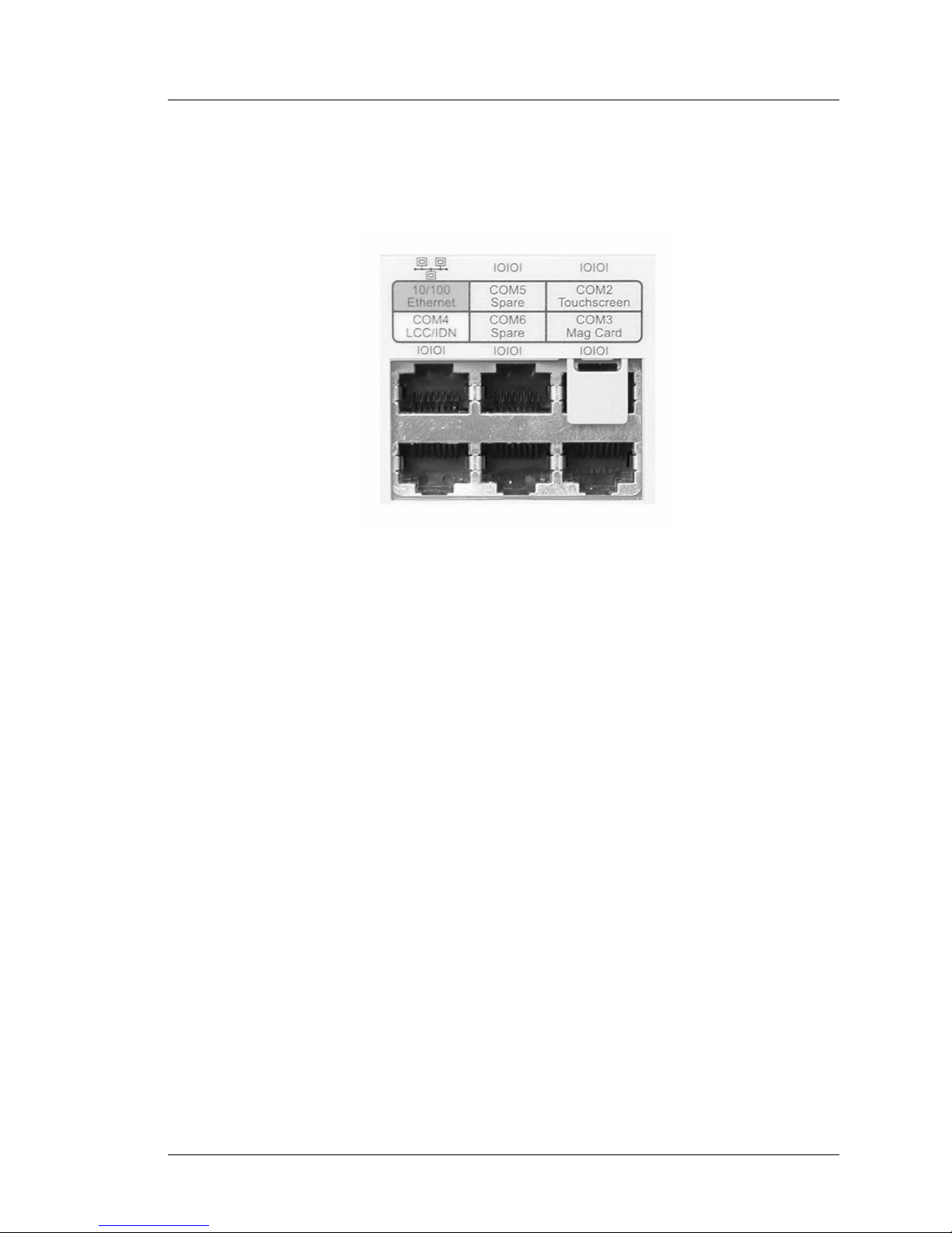
The Modular Connector Block
Figure 1-6 shows the bank of six modular connectors located on t he Ecl ips e Fr ont I /O
Panel, described below.
Figure 1-6: The Front Panel Modular Connectors
10/100 Ethernet
The Eclipse system board includes a PCI based 10/100 Ethernet controller with a
10BaseT connector on the fr ont con nector panel . The Ecl ipse i s not p rovide d with
a Category 5 patch cable, it must be purchased separately.
COM 5 (Spare)
8-Pin modular connector is configured as COM5 - Spare COM Port.
COM 2 (Reserved For Touchscreen)
COM2 is dedicated to the Eclipse Touchscreen interface which resides in the
LCD/T ou chscr een Head. Note the block pr eventi ng the use of COM2 as shown in
Figure 1-6.
COM 4 (LCC/IDN Port)
This port supports MICROS IDN printing devices. The default setting for this
COM port matches the configuration required to support IDN printing from
application software such as 3700. Like previous LCC/IDN ports, it has RS422
and RS232 capability. See Appendix B for connector and cabling information.
COM 6 (Spare)
8-Pin Modular connector configured as COM6 - Spare COM Port. However, by
default, COM6 is disabled i n CMOS Setup i n order t o free up I RQ5 for use by the
on-board sound chip.
PCWS Eclipse Setup Guide 1-15
Page 28

What Is The Eclipse Workstation?
The I/O Panel
COM 3 (Reserved for Mag Card Reader)
This port is configured as COM 3. It is res erved for the front panel 3-track card
reader.
Internal Speakers
The I/O Panel includes a pair of jacks for the front mounted speakers. Plug the right
speaker into the top connector and the left speaker into the bottom connector.
USB
The Universal Serial Bus (USB) interface supports the host controller functions with a
built-in Root Hub and 2 USB ports. The USB circuitry is implemented based on
OpenHCI, the Open Host specification for USB.
USB is based on a tiered star topology that runs at a data rate of up to 12Mb per
second. All USB devices are Plug and Play compatible, and can be connected to the
Eclipse when power is on. This means that each device can be recognized without
rebooting the workstation.
The 12Mb/s data rate provid es suff icient throughput to supp ort externa l storage me dia
such as CD-ROM drives, ZIP drives, and digital scanners and cameras.
The Eclipse fully supports a USB floppy diskette which is capable of booting the
workstation.
Mouse
This port accepts a PS/2 style mouse or other pointing device.
Keyboard
This port accepts a PC keyboard with a PS/2 style connector.
RS232 Serial, DB9 Connector (COM1)
This industry standard DB9 male connector can be used for an external modem, or
other serial peripheral device. This port is supported by an industry standard 16550
UART with a 16-byte receive buffer. BIOS default settings configure this port at
COM1.
Parallel Port
The parallel port is an industry standard Centronics parallel interface. In addition, the
parallel port also supports the EPP and ECP standards.
Digital Visual Interface (DVI) Connector
This connector provides both a standard VGA output for connecting a conventional
CR T mo nit or (requires a special cable), or supports the Digital Visual Interface (DVI)
interface to the LCD panel.
1-16 PCWS Eclipse Setup Guide
Page 29
What Is The Eclipse Workstation?
The I/O Panel
Cash Drawers 1 and 2
These connectors support standard and low profile MICROS cash drawers with DIN
style connectors.
Remote Display
This connector supports a pole mount Remote Customer Display. This display
contains a two line di splay with 20 characters on each line. The display can be
mounted up to 6 feet from the workstation.
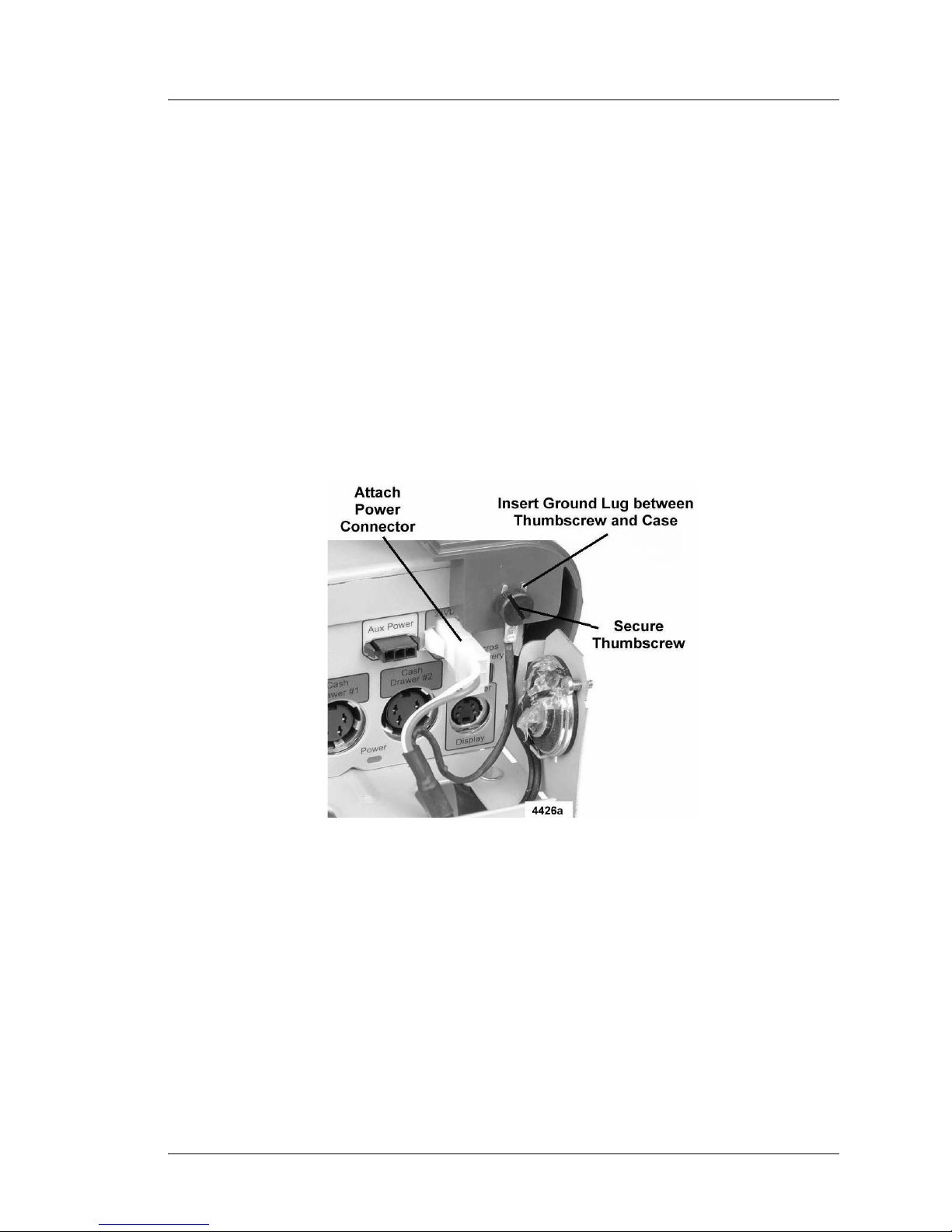
+24V Printer Power
This connector provides +24V t o power a single printer such as the U220 or TMT-88.
A 24 inch version of this cable is currently available, with extended versions planned
for the near future. Figure 1-7 shows how to install the external cable.
In late 2004, the internal power supply to front panel cable has been modified to
include a 4A, 125V Axial Lead fuse in series with the +24VDC line.
Figure 1-7: Connecting the Printer Power Cable to the Eclipse
Auxiliary Power Connector
This connector appears in units assemble d after Se ptember 2001. It provide s both + 5V
and +12V for use by a future product such as a Smart Card Reader or Magnetic Card
Reader/Writer.
A pin diagram of this connector can be found in Appendix.
In late 2004, the system board to front panel cable has been modified to include a p ai r
of 5A, 125V, Axial Lead picofuses (Littlefuse R251005) in series with the +5VDC
and +12VDC outputs.
PCWS Eclipse Setup Guide 1-17
Page 30

What Is The Eclipse Workstation?
Connecting Peripherals to the Eclipse
Connecting Peripherals to the Eclipse
The following section describes how to connect a variety of devices to the Eclipse
Front I/O Panel.
USB Floppy Disk Drive
The TEAC Model FD-05PUB Floppy Disk Drive with USB Interface is the only
supported Eclipse Floppy Disk Drive. Other USB drives may not function. The drive
is available at your local computer supply store, or through MICROS with P/N
700352-085.
Although a Floppy Disk Drive is not required in most d ay- to- day POS applications, it
is required to configure a hard disk, or run disk based diagnostics software.
The default BIOS settings are configured to boot from the USB Floppy Disk Drive if
it is attached and a diskette in place. If the Fl oppy Disk Drive is not installed, or a
bootable disk is not present in the drive, the workstation will boot from the Hard Disk
or LAN as required.
USB Floppy Diskette Drive Letters
This section describes how the Drive Letter designation of the USB Floppy Disk
Drive behaves before and after the USB floppy drivers are installed.
DOS
When booted to the DOS command line, or to the Windows 95/98 command
prompt, the drive functions as a standard A: Drive.
Windows 95
When installed with a copy of Windows 95 where the USB upgrade
(USBSUPP.EXE) has not
the A: drive in Explorer. This is how the Windows 95 version of the Eclipse hard
disk image is supplied.
If you run the USBSUPP.EXE patch (located in c:\b\usbsupp) to upgrade
Windows 95 USB capabilities, two instances of the Floppy Drive appear in
Explorer. The first, drive A, produces an error message if you atte mpt to acce ss it.
A second Floppy driver letter representing the TEAC USB Floppy will appear
after the last hard disk or hard disk partition hard drive letter.
Windows 98
When connected to an Eclipse running Windows 98, two instances of the Floppy
drive appear in Explorer. The first, drive A, produces an error message if you
attempt to access it. A second Floppy driver letter representing the TEAC USB
Floppy will appear after the last hard disk partition drive letter.
been applied, the USB Floppy Disk Drive appears as
Windows NT 4.0
To use the USB Floppy under Windows NT 4.0, you must install the TEAC USB
Floppy drivers. This d river is suppli ed on the NT 4. 0 image , bu t is not in stall ed by
default.
1-18 PCWS Eclipse Setup Guide
Page 31

What Is The Eclipse Workstation?
Connecting Peripherals to the Eclipse
A shortcut called Usb_flop is located on the desktop. Double-click this icon to
install support for the USB Floppy Disk. Once the driver is installed, the USB
floppy diskette operates in the same manner as a legacy floppy using drive letter
A: If the driver is not installed, Windows NT 4.0 will not see the USB floppy
drive.
Windows 2000 or XP Professional
Connect the drive . Dr ivers are not required. The floppy disk appears as drive A in
Windows Explorer.
Setting the USB Floppy Disk Drive to Boot the Workst ation
The default settings in CMOS Setup are configured to boot the workstation from the
floppy disk if it is present and a diskette is inserted.
If the workstati on r ef use s to boot from the USB Floppy Disk Drive, and the Eclipse is
running BIOS version 1 .00.22 or l ater , check the Boot Order Seq uence in BIOS Setup.
The following procedure describes how to configure the BIOS to boot from the USB
Floppy.
1. Start the workstation and enter BIOS Setup Utility by pressing [F2] when
prompted.
o The Main Menu appears.
2. From the ‘Main’ Menu, select the ‘Boot’ Menu.
o The ‘Boot Menu’ appears displaying the current boot configuration. When
booting the works ta ti on, the BIOS checks each device in the list, from the to p
down, looking for an operating system.
3. Use the Up/Down cursor control keys to select the ‘+Removable Devices’ field.
Pressing [Enter] at this point displays a list of the removable devices installed, in
this case, the TEAC FD-05PUB-(USB). Pressing [Enter] again closes the list.
4. Press the [+] or [- ] as re qui red to move the ‘+Removable Devices’ field to the top
of the list.
5. Press [F10], then [Enter] to save changes and boot from the Floppy Disk Drive.
PCWS Eclipse Setup Guide 1-19
Page 32

What Is The Eclipse Workstation?
Connecting Peripherals to the Eclipse
Connecting the Eclipse to a LAN
Figure 1-8 shows the Eclipse Ethernet connector located on the upper left of the
Modular connector block.
Figure 1-8: The Ethernet Connector and Status LEDs
When you attach the Eclipse to a LAN, the three status LEDs shown at the lower half
of Figure 1-8 provide the connection status. The table in Figure 1-9 summaries the
function of each LED.
Link
The Link LED, when ON, indicates that the workstation is physically connected to a
device such as a hub or patch panel.
FD (Full Duplex)
When the Link LED is ON, the FD LED indicates if the Eclipse is connected to a full
or half-duplex LAN. The operation of the Link and FD LEDs is summarized in the
table below.
Active
The Active LED indicates that inf ormatio n is being wri tten to or re ad from th e Eclipse
Workstation over the LAN.
LINK FD Status
ON ON Full Duplex Connection = 100 Mbps
ON OFF Half Duplex Connection = 10 Mbps
OFF OFF No Connection
Figure 1-9: The Eclipse LINK and FD LEDs
1-20 PCWS Eclipse Setup Guide
Page 33

Operating the Eclipse
On the following pages, you’ll find several procedures for operating the Ecli pse.
Turning the Workstation On and Off
The upper half of Figure 1-10 shows the location of the Eclipse Power Switch. The
lower half of the illustration shows the location of the power indicator visible only
when the Front Cover is removed.
What Is The Eclipse Workstation?
Operating the Eclipse
When the workstation is OFF, pressing the power button will turn it on.
When the Eclipse is ON, pressing and holding the power butt on for four seconds
turns the Eclipse off.
NOTE: Starting with Eclipse BIOS Version 1.00.20 or later, a setup option can force
the workstation to restart after a power failure with out user intervention. See Chapter
2 for more information.
PCWS Eclipse Setup Guide 1-21
Figure 1-10: Using the Eclipse Power Switch
Page 34

What Is The Eclipse Workstation?
Operating the Eclipse
Using the Magnetic Card Reader
The card reader is mounted on the front cover of the workstation for easy access and
service. Figure 1-11 shows that you can swipe a card in either direction, with the mag
stripe facing down and towards the rear of the workstation.
Magnetic cards should always be kept dry, and away from magnets or sharp objects
that could damage the encoded inf ormat ion on the card. If a mag card is damp or wet,
or appears damaged in any way, DO NOT insert into the reader.
Figure 1-11: Using the Magnetic Card Reader
If the unit does not read the mag cards cons istently, the read head may be dirty or
contaminated. A cleaning card can be used to clean the reader head. This type of card
has a felt strip in pl ac e of the mag stripe which cle ans the head as it is swiped through
the reader.
Calibrating the Touchscreen
Calibrating the touchscreen is the process of aligning the touchscreen glass with the
underlying video display. If the touchscreen is not calibrated, the active area of the
touchscreen beneath the display may not be aligned properly or may be too small in
size.
When to Calibrate the Touchscreen
• When the video resolution changes from one setting to another (e.g, changing
from 640x480 to 800x600 or 1024x768).
• Any time the cursor does not follow the movement of your finger, or does not
reach the edges of the touchscreen.
• If the LCD/Touchscreen head has been swapped out for another unit. New
touchscreen drivers may be required. Three versions of the head are now
available:
1-22 PCWS Eclipse Setup Guide
Page 35

What Is The Eclipse Workstation?
Operating the Eclipse
o The original 12.1” DSTN or TFT LCD/Touchscreen head (400497-001 or
400497-002) with a 3M MicroTouch Excalibur controller.
o The recent 12.1” LCD Head/T ouchscree n (400497-003A) wit h the Hampshire
TSHARC touchscreen controller.
o The 15” LCD/Touchscreen Head.
Tips for Performing the Calibration Procedure
• Perform the calibration procedure in the position (sitting or standing) that the
touchscreen is normally used.
Calibrating the MicroTouch TouchWare Drivers
1. From the Desktop, press the MicroTouch T ouc hWare icon twice. If this is the first
power-up after the LCD/Touchscreen head has been swapped out, you may be
prompted to run the calibration procedure.
2. Select the Calibrate tab.
3. Press the Calibrate button.
o Two calibration targets appear on the screen. A hand points to first target, in
the lower left quadrant of the screen.
o If you press [ESC] or do not touch the screen within 20 seconds, the
calibration process aborts with no change in calibration values.
4. The hand points to the first calibration target, in the lower left corner. Position
your fingertip to completely cover the target and touch the screen without letting
go. Continue holding the touch until the message “Touch Enabled” appears.
5. Continue the procedure by repeating Step 4 on the next target.
6. When calibration is complete, a dialog box prompts you to test the calibration.
o Drag your finger across the screen and make sure the cursor follows your
movements. Touch each corner and touch along each edge of the screen to
verify that the cursor can reach the display area.
o If you must re-calibrate, make sure to touch the targets carefully. It is possible
that you did not hold the touch long enough, or that you accidently touched
the screen in the wrong place during the calibration procedure.
Calibrating the Hampshire Touchscreen Drivers
1. From the Desktop, select Start -> Programs -> Hampshire Touchscreen Control
Panel.
2. Select the Calibration tab.
Press the [Configure] button to define the calibration type, offset, and target type
in additon to choosing a 3, 4, 7, or 20 point test.
PCWS Eclipse Setup Guide 1-23
Page 36

What Is The Eclipse Workstation?
Operating the Eclipse
Using the 15” LCD/Touchscreen Head Controls
The 15” LCD/Touchscreen head includes a set of controls loca te d alo ng the right side
of the display housing. They provide access to the On Screen Display (OSD) menu
and power/on off fu nctions. By de fault, t hese contr ols are di sabled, but can be enabl ed
by using the instructions below.
The Power On/Off button allows the 15” LCD/T ouc hscreen Head to be powered down
independently of the Eclipse system unit.
The On Screen Display menu provides access to brightness and contrast controls, and
other display related functions.
Figure 1-12, below, shows how to enable the Power On/Off button and On Screen
Display.
Figure 1-12: Enabling the Power Button and OSD Controls
• T o enable the Power On/Off button, simultaneo usly press and ho ld the MENU and
Down Arrow buttons as shown at the left of the illu stration.
o A window appears and displays the message “Power Unlock” to indicate the
Power On/Off button is enabled. If you continue to hold the MENU and
Down Arrow buttons, the message toggles between “Power Unlock” and
“Power Lock.”
• T o enable the On Screen Dis play menu, simultaneousl y press and hol d the MENU
and Down Arrow Keys.
o When the OSD appears, use the Up or Down Arrow buttons to select an item
from the menu, then press SELECT. Use the Up or Down Arrow buttons to
adjust your selection, then press SELECT when complete.
1-24 PCWS Eclipse Setup Guide
Page 37

BIOS Setup Utility
The Phoenix BIOS Setup Utility provides a central location for configuring
the Eclipse system board hardware. The BIOS Setup Utility is stored in Flash
EPROM, so it is available even if a hard disk or operating system is not
installed.
Chapter 2
All settings are stored in battery protected CMOS RAM for retention when
AC power is off.
For information on the latest BIOS versions and upgrades, see the hardware
support section of the MICROS web site at micros.com.
In this chapter
Starting the P hoenix Setup Utility/Ch ecking the MICROS BIOS Version ..2-2
Main............................................................................................................. 2-4
Advanced..................................................................................................... 2-7
Power..........................................................................................................2-11
Boot............................................................................................................ 2-12
Exit............................................................................................................. 2-14
PCWS Eclipse Setup Guide 2-1
Page 38

BIOS Setup Utility
St arting the Phoenix Setup Utility/Checking the MICROS BIOS Version
Star ting the Phoenix Setup Utility/Checking the MICROS BIOS
Version
The following procedure describes how to determine the MICROS BIOS Version
number of the Eclipse and how to enter the BIOS Setup Utility.
Requirements:
A PC Keyboard with a PS/2 style connector.
Procedure:
1. Attach a PS/2 keyboard to the front panel connector and the AC power cable to
the power supply.
2. Press the power button located on the right side of the unit.
3. To check the MICROS BIOS Version, wait about 20 seconds for the BIOS Splash
screen to appear, then the [Pause/Break] key to freeze the display. The fourth line
from the top of the screen indicates the MICROS BIOS Version in the form of
v1.xx.xx. This manual documents additions and changes to the BIOS up to
Version 1.00.22, and is current through November 2004.
4. To enter the CMOS Setup Utility, press the [F2] key when prompted.
o You should be at the PhoenixBIOS Setup Utility main screen.
o For information on how to navigate each menu and make selections, press
[F1] or check the help information at the bottom of the screen.
o There are five primary sections: Main, Advanced, Power, Boot, and Exit. An
overview of each selection follows.
Main
This menu lets you set the system da te and t ime, def ine the type of hard di sk inst alle d,
and display the total amount of memory installed on the system board.
Advanced
This menu provides access to settings for the Eclipse COM ports, LPT port, and mag
card reader.
Power
This menu provides access to the Eclipse power saving modes. A pre-configured
power saving mode may be used or the user may configure a power saving mode
manually by defining several parameters. Power settings are disabled by default.
2-2 PCWS Eclipse Setup Guide
Page 39

BIOS Setup Utility
Starting the Phoenix Setup Utility/Checking the MICROS BIOS Version
Boot
This menu allows the user to determine the Eclipse boot device sequence. The boot
device may be an external USB Floppy Disk Drive, internal IDE hard disk, network
boot ROM, or optional Disk On Chip.
Exit
You may save your changes and exit, discard your changes, or load default setup
values from this menu.
Keys Used During Setup
The table below summarizes the functi on of the keys that appear on the bottom of the
Setup Utility help screen.
Key(s) Description
[F1] Display general help from any screen in the
Setup Utility
[ESC] Jumps to the Exit Saving Changes field from
any screen in the Setup Utility
<- or -> Selects a menu item to the left or right
Up or Dn Moves the highlight field up or down or
between fields
[-] minus key Scrolls backwards through values for the
highlighted field
[Shft]+[+] or
Space
[F5] Scrolls backward through values for the
[F6] Scrolls forward through values for the
[Enter] Enters sub-menu, or brings up a selection
[Home] or
[PgUp]
[End] or
[PgDn]
[F9] Load Setup Defaults from any screen in the
Scrolls forward through values for the
highlighted field
highlighted field. Same as [-].
highlighted field. [Shift]+[+] or Space
menu for the highlighted field
Moves the cursor to the first field
Moves the cursor to the last field
Setup Utility
[F10] Save changes and Exit from any screen in the
PCWS Eclipse Setup Guide 2-3
Setup Utility
Page 40

BIOS Setup Utility
Main
Main
The following section describes the settings found in the Main screen and lists the
recommended default where possible. Some of the fields only appear if you have the
BIOS version noted in the heading. This documentation covers the Eclipse BIOS
version up to 1.00.22. Some fields appeared in BIOS Version 1.00.20, which was
available only on the Micros web si te. Complete BIOS releas e notes ar e provide d with
the BIOS located on the web site.
System Time:
System Date:
These fields allow you to set the system time and date. Time is entered in the 24-hour
military time format. For example, 1PM is 13:00:00, 6PM is 18:00:00, and so forth.
Use the -/+ keys to select a value, then press enter to advance to the next field.
Legacy Diskette A: [Disabled] (BIOS Version 1.00.20 or later)
This sub-menu determines if a legacy Floppy Diskette installed, and defines the type.
The Eclipse does not include a legacy floppy interface. However, this selection is
present to maintain compatibility with disk images created for previous workstations
and their ability to support diskless operation. Select “1.44/1.25 Mb 3½” when the
Eclipse is used as a RES/3700 diskless client.
Primary Master [Auto]
The Primary Master is the only hard drive supported by the Eclipse. To change or
examine the settings in the Primary Master field, scroll to the selection and press
[Enter].
We recommend the default setting of ‘Auto’. It forces the BIOS to automatically
detect the hard drive parameters and optimal settings each time the workstation boots.
If a hard disk is not installed, the Primary Master field will display [None].
When the cursor is located on the Primary Master field, pressing [Enter] shows the
available settings. The default settings for each field are shown in brackets [].
Translation Mode [Assisted LBA]
We recommend that you leave this field at the default setting of “Assisted LBA”
when installing a new hard disk of any size. The alternat e setting , ECHS, could be
used if you move a hard disk from a PCWS Ult ra or other computer to the Ecl ipse
and it refuses to boot. This problem is seen as a blinking cursor in the upper left
corner of the LCD. However, we do not recommend moving a hard disk from an
older MICROS PCWS or desktop computer into the Eclipse without installing an
Eclipse image. The Eclipse image contains the correct drivers for the Eclipse
hardware.
o To toggle the Translation Mode, press [Enter], select [ECHS] or [Assisted
LBA], and press [Enter] again.
2-4 PCWS Eclipse Setup Guide
Page 41

BIOS Setup Utility
Type [Auto]
This field displays the primary master device. Pressing [-] scrolls through the
possible selections.
None
This setting can be used if no hard disk is installed (i.e., the workstation is
diskless). However, the default ‘Auto’ setting , (see bel ow) can be used as well
for a diskless workstation.
Auto
This is the default setting. If an IDE hard disk is installed, the BIOS
automatically detects its parameters and optimal settings each time the
workstation is powered -up. If the hard disk i s removed o r a diff erent har d disk
is installed at a later time , because the BI OS detects the hard disk ea ch time
the workstation bo ots, it do es not generate P OST error s about a d efective hard
disk or hard disk interface.
User
Main
The User specified setting allows you to manually enter the hard disk’s
Cylinders, Heads, and Sector (CHS) data from a keyboard, but this is not
recommended. This se tting sh ould be u sed only if the hard d isk is n ot detec ted
with the ‘Auto’ setting, and only if you can specify the correct CHS data for
the drive.
Other ATAPI
N/A
ATAPI Removeable
N/A
IDE Removable
Refers to IDE versions of the ZIP Drive or Super Drive.
CD-ROM
The CD-ROM setting is normally disabled. CD-ROM support for the Eclipse
is provided by a Parallel Port Backpack external CD-ROM reader, or through
various external PCMCIA and USB CD-ROM drives.
Primary Slave [None]
The Eclipse workstation supports a single IDE Hard disk internally, the Primary
Master. However, if you have a dual-drive ATA/66 IDE ribbon cable with three
connectors and a “Y” cable adapte r to power both dri ves , set this fi eld to [Auto], then
reboot the workstation to allow the BIOS to detect the IDE device you have installed
temporarily. Be sure the master/slave jumpers on the second devi ce you inst al l ar e set
to slave.
Secondary Master [None]
Secondary Slave [None]
PCWS Eclipse Setup Guide 2-5
Page 42

BIOS Setup Utility
Main
The Eclipse does not support a secondary IDE master or slave device. A connector is
not provided on t he sys tem board. The BIOS does not e nable th is inte rface an d assigns
IRQ 15 to COM3.
PC Beep Mute [Disabled]
This setting determines if the beeper located on the system boa rd functions during the
Power On Self T est. The default setting of disabled allows the internal beeper to sound
during POST.
Selecting [Enabled] mutes the internal beeper. The external speakers are not affected
by these settings.
After Power Failure [Stay Off] (BIOS Version 1.00.20 or later)
This field determines how the Eclipse recovers from an unexpected AC power failure
while in operation. The selections are [Stay Off], [Power On], and [Last State].
The default setting of [Stay Off] requires the user to press the power button to restart
the workstation after an unexpected AC power failure.
The [Power On] setting causes the Eclipse to automatically restart when AC power
returns after an unexpected AC power failure.
The [Last St ate] set ting shou ld be used in conju nction wit h the power saving mod es. If
the Eclipse is in a sleep mode and AC power fails, when it returns, the workstation
should resume the sleep mode state it was in before the AC power failed.
LAN Boot Function: [Disabled]
The ability of the Eclipse to boot from a LAN or from the Disk On Chip is mutually
exclusive. Thus, if a Disk On Chip is installed, and you must boot from the LAN, set
this field to [Enabled].
System Memory
Extended Memory
These fields are for informational purposes on ly. The size of “System Memory” will
typically be 640K. The size of “Ex tended Memory” fie ld is deter mined by t he number
and size of DIMMs installed on the system board. The sum of the System Memory
and Extended Memory fields minus the 1M the BIOS reserves for video will roughly
equal the total amount of DIMMs installed on the system board.
2-6 PCWS Eclipse Setup Guide
Page 43

Advanced
This menu is a gateway to several sub-menus where you access many of the Eclipse
hardware features including the peripheral port s. The default settin g for eac h fie ld are
shown in [ ].
Several fields first appeared in BIOS Version 1.00.20, available only on the Micros
web site. BIOS release not es, detailing each change are included in the ZIP file on the
MICROS web site.
Installed O/S: [Wi n95]
This selection allows you to define the operating system installed on the hard disk.
Windows 95 is the default setting.
BIOS Setup Utility
Advanced
WARNING:
The ‘Installed O/S’ field must be set to match the operating
system that will be in u se. In addi tion, the s etting must be made
before the inst al lation begins. If you are installing an operating
system other than Win95, change this setting to match. This
includes Windows 98, Windows ME, and Wi ndows 2000. For
DOS/WFW 3.1, or Windows NT installations use the ‘Other’
setting.
An incorrect OS setting can cause some operating systems to
display unexpected behavior.
Reset Configuration Dat a [No]
This field is normally set to [No]. When you select [Yes] and restart the workstation,
the BIOS clears, then rebuilds the Extended System Configuration Data (ESCD) data
area. The ESCD data area contains a table of the plug and play hardware detected by
the BIOS. This data area is examined by plug and play compatible operating systems.
Once the BIOS rebuilds the ESCD data, this field returns to [No].
PS/2 Mouse [Enabled] (BIOS Version 1.00.20 or later)
This selection enables or disables the front panel PS/2 Mouse port. The selections are
[Enable], [Disable], and [Auto Dete ct]. The default setting of [Enabled] al lows the
operating system to detect and use the mouse, if present. When set to [Disabled], the
mouse port is disabled and IRQ12 becomes available for other uses.
Note: The PS/2 Mouse Field must be set to ‘Disabled’ to support a COM1 serial
mouse under DOS and Windows for Workgroups.
PCWS Eclipse Setup Guide 2-7
Page 44

BIOS Setup Utility
Advanced
IO Device Configuration ->
This sub-menu allows you to enable or di sable the Ecl ipse’s six COM ports and singl e
LPT port. Press [Enter] to view the following selections, described below.
COM1: [Enabled - IO Addr=3F8, IRQ=4]
This selection enables or disables the front panel DB9 serial connector. The
default setting is “Enabled”. Select “Disabled” to turn off the port and use the
resources elsewhere.
COM2: [Enabled - IO Addr=2F8, IRQ=3]
This selection enables or disables COM2, used for the Touchscreen Interface in
the Eclipse.
COM3: [Enabled - IO Addr=3E8, IRQ=15]
This selection enables or disables COM3, used for the 3-Track Mag Card reader
mounted to the front of the Eclipse.
COM4: [Enabled - IO Addr=2E8, IRQ=11, RS422+]
This selection enables or disables and define s oper ati ng mo des of COM4, a
multi-purpose RS422 or RS232 port. When the port is enabled, the following
modes are available.
Mode: [RS422+]
The default ‘RS422+’ mode supports MICROS IDN printing devices from
applications such as 3700.
Mode: [RS422-]
This setting supports the rare instances where the Eclipse is connected to a
Local Cluster Controller (LCC), Remote Cluster Cont roller (RCC), or
Network Cluster Controller (NetCC), as part of an 8700 installation. Other
applications do not support this type of interface.
Mode: [RS232]
This mode enables a two -wire RS232 interface capable of driving peripher als
such as an cash drawer or printer. Handshaking signals are not available on
this interface. See Appendix B for co nnec tor pin- out s and examples of cables
that can be used with this port.
COM5: (Enabled - IO Addr=338, IRQ=6]
This selection enables or disables COM5, a spare COM port not dedicated to a
particular device. This port is not available when using the Windows 2000
operating system.
2-8 PCWS Eclipse Setup Guide
Page 45

BIOS Setup Utility
Advanced
COM6: [Disabled - Use IO Addr=238, IRQ=5]
This selection enables or disable s COM6, a spare port not dedicate d to a par ticular
device. However, by default, this port is disabled to allow the on-board sound
hardware to use IRQ5. If you enable the port, use the IO Address and IRQ line
specified above. However, the on-board audio hardware will not function.
NOTE:
To enable COM5 and or COM6 under Windows NT 4.0
Workstation, first enable the port setting in BIOS, then start
Windows and go to Start -> Control Panel -> Ports. Enter the
IO Address and IRQ settings shown for each port
Parallel Port [Enabled]
This selection configures the front pa nel parallel port connector. Select
“Disabled” to turn off the port and use the assigned resources elsewhere. Select
“Enabled” (default) to set the port resources manua lly.
Mode: [SPP]
This select ion defines the parallel port mode. In m ost cases, th e driver
software for a typical device (a parallel port CD-ROM drive for example)
enables the fastest possible parallel port configuration. Press [-] to toggle
through each selection.
“[EPP]” selects the Enhanced Parallel Port mode.
“[ECP]” selects the Extended Capab ilities Parallel Port mode.
“[SPP]” selects the Standard Parallel Port mode.
Base I/O address:[378]
The Base IO address de te rmines the LPT port designat ion of the parallel port.
Two selections are available. [378] corresponds to LPT1 and [3BC]
corresponds to LPT2.
DMA Channel: [DMA 1]
If the parallel port Mode is set to “ECP”, you must assign it either DMA
Channel 1 or DMA Channel 3. DMA 1 is recommended.
Magnetic Card Reader Mode [Special]
This field determines how magnetic card data is processed by the Eclipse
workstation. The selections are Magtek and Special.
Magtek
When Magtek mode is selected, card data is processed to appear as if it were
entered through a PC keyboard. However, this means that card data such as
the LRC (Longitudinal Redundancy Check) is not available to applications
that may require them. This mode supports MICROS employee and manager
sign-on cards.
PCWS Eclipse Setup Guide 2-9
Page 46

BIOS Setup Utility
Advanced
MIDI port: [Disabled]
Local Bus IDE Adapter [Primary]
This selection enables/disables the system board IDE interface . By default, t his
selection is “Enabled” to ensure a hard disk can be detected automatically when it is
installed.
Advanced Chipset Control ->
This sub-menu enables support for Legacy USB devices. Press [Enter] to view the
single selection, descri bed bel ow.
Legacy USB Support: [Enabled]
Special
When [Special] mode is enabled, card data is placed in a buffer unmodified,
where it can be accessed through the Eclipse API. The API allows the
application full access to mag card data and is typically used for credit card
authorization applications.
Enables built-in BIOS support for a USB Keyboard and or Mouse.
2-10 PCWS Eclipse Setup Guide
Page 47

Power
BIOS Setup Utility
Power
This menu provides access to the Ec lipse System Boar d power s aving f eature s. Power
savings are disabled by default.
Power Savings: [Disabled]
When set to [Disabled], power management features are turned off and will not
function regardless of the other settings in this menu.
[Disabled] - Turns off all power management features. This setting is
recommended for most applications.
[Maximum Performance] - This selection conserves less power, but allows the
workstation to return to an operational state in the least amount of time. When
enabled, the [Standby Timeout] field is set to 16 minutes and the [Auto Suspend
Timeout] field is set to 60 minutes.
[Maximum Power Savings] - This selection provides the greatest amount of
power savings but the workstation will take longe r to return to a n operationa l
state. When enabled, the [Auto Suspend Timeout] field is set to 5 minutes.
[Customized] - Allows the user to define the Standby Timeout and Auto Suspend
Timeout intervals. When Customized is selected, you must enter timeout values
for the fields listed below.
[Standby Timeout]
The available selections are off, 2, 4, 6, 8, 12, or 16 minutes. After the
designated time has el apsed, Standby Mode turns off various devices in the
system, including the screen, until you start using the system again (by
moving the mouse or using the keyboard).
[Auto Suspend Timeout]
Determines the amount of time the works tation must be in St andby Mode (s ee
above) before it enters the Suspend mode. The available selections are off, 5,
10, 15, 20, 30, 40, and 60 minutes.
Resume On Time: [Off]
This selection wakes the syst em at a specified time. The av ai lab le sel ect ions are [Off]
and [On]. When [On], the wake up time is specified in the Resume T ime: fi el d, below.
Resume Time: [00:00:00]
Then the Res ume On Time field is enabled, ente r the time when the workstat ion
should resume operation in 24 hour format.
Resume On Modem Ring: [Off]
When set to [Enabled] ca n power up the workstation from the Suspend state when an
external modem receives a call.
PCWS Eclipse Setup Guide 2-11
Page 48

BIOS Setup Utility
Boot
Boot
When the workstation is turned on, entries in the Boot Menu determine the order in
which the BIOS searches for an Operating System (O S).
The boot sequence is displayed as a series of major headings, an example of this is
shown below. Each of the four fields are listed below with a brief explanation of the
devices you may find. If a [+] appears to the left of a heading, it indicates multiple
devices are included.
[+Removable Devices] - (TEAC USB Floppy Disk Drive)
[+Hard Drive] - (System Hard Disk, Optional Disk On Chip)
[ATAPI CD-ROM Drive]
[MBA UNDI (Bus1 Slot0)] - (LAN Boot Selection)
When searching for a bootable device, the BIOS works from top to bottom, checking
multiple devices under each heading if available, bypassing devices if they are not
installed. The default boot order is shown above.
You can promote devices, or move them higher in the sequence by sc rolling to the
heading and pressing [Shi ft]-[+ ]. For example, i f your workst ation is diskl ess, you can
scroll to the [MBA UNDI (Bus1 Slot0)] heading and press the [Shift]-[+] key
combination three times to promote this heading to the top of the boot list.
[MBA UNDI (Bus1 Slot0)]
[+Removable Devices]
[+Hard Drive]
[ATAPI CD-ROM Drive]
You can demote a heading by scrolling to it and pressing [-].
However, we recommend that you leave the default settings as provided, with the
removable drive first in the list. If the USB Floppy is not attached, it takes the BIOS
very little time to determine this and move on to the next device in the list. This allows
you to install a USB floppy at any time and use it to boot the workstation without
having to alter the boot sequence.
2-12 PCWS Eclipse Setup Guide
Page 49

BIOS Setup Utility
Boot
When a heading such as [Hard Disk] contains multiple devices, each device can be
promoted or demoted usi ng the same keyboard commands used to promote o r demote
a heading. The configuration below shows the [Hard Drive] heading expanded to list
individual devices.
[+Removable Devices]
[-Hard Drive]
ST360021A - (Typical 60G or 80G hard disk)
M-Systems DiskOnChip (c) - (An M-Systems Disk On Chip is installed)
Bootable Add-in Cards - (Not Installed)
[ATAPI CD-ROM Drive]
In this example, a hard disk as well as the M-Systems Disk On Chip (DOC) is
installed. The Eclipse is capable of booting from either of these devices, however the
BIOS checks the hard disk first because it is first in the list. The “Bootable Add-in
Card” field that appears in the list could apply to certain types of PCMCIA cards
which contain flash memory.
To boot from the DOC instead of the hard drive, promote it to the top of the list by
scrolling to the [M-Systems DiskOnChi p (c)] field and pressing [Shift]-[+] once to
move it to the top of the list .
The Eclipse can b oot dire ctly fr om the DOC if you press the Micros Recover y Butto n,
located on the front panel, and restart the workstation. Pressing this button sets a
recovery bit in the CMOS RAM which is checked by the BIOS at each power up.
When the recovery bit is set, the BIOS ignores the default sequence and boots from
the Disk On Chip where some for m of backup and recovery s oftware r esides. If a Disk
On Chip is not installed when the recovery button is pressed, the workstation will
attempt to boot from the LAN. More information about installing and configuring a
Disk On Chip can be found Chapter 3.
PCWS Eclipse Setup Guide 2-13
NOTE
In the example above, also note that the [MBA UNDI (Bus1
Slot0)] LAN Boot heading is missing because a Disk On Chip
is installed. To force the Eclipse to boot fr om the LAN, go to
the BIOS Utility Main page, and set the ‘LAN Boot Function’
to ‘Enabled’, [F10], then [Enter] to save and reboot.
Page 50

BIOS Setup Utility
Exit
Exit
When you have made all of your selections from the various menus within the Setup
Utility, you must save your changes and exit. Selecting EXIT from the Menu Bar
selects the EXIT menu.
Exit Saving Changes
If you have made any changes to CMOS settings, use this selection to ensure that the
changes you made are saved in CMOS RAM. CMOS RAM is a type of non-volatile
RAM whose content is protected by the Lithium coin cell on the Eclipse System
Board.
When you select this option, a confirmation is requested. Select [Yes] to save changes
to CMOS RAM, exit CMOS Setup, and restart the workstation.
You may also press [F10], t he n [ Ent er] from any menu to s ave ch anges and reboot the
workstation.
Exit Discarding Changes
Use this option only if you do not want to save any of the changes you have made in
the Setup Utility. If you have made changes to any fields other than the system time,
date, and password, a confirmation appears.
Load Setup Defaults
This option allows you to load default values into each parameter of all Setup menus.
When this option is sel ected, or the [F9] key press ed, confirmati on is req uested. Select
[Yes] to load default values. You may either Exit Saving Changes now or continue to
make changes before saving the values to CMOS RAM and exiting.
Discard Changes
This option allows you to discard any selections you have made, and restore the
previous values. When you select t his opti on, a confi rmation i s requested. Select [ Yes]
to discard any setti ngs you have changed, but not restart the workstation.
Save Changes
This option allows you to save your current selections without exiting the Setup
Utility, allowing you to return to other menus and make changes. When you select this
option, a confirmation is requested. Select [Yes] to save any changes to CMOS RAM.
2-14 PCWS Eclipse Setup Guide
Page 51

PCWS Eclipse Hardware
Configuration
In this chapter
Disassembling the Eclipse............................................................................3-2
What’s Inside?.............................................................................................. 3-8
Remove/Replace the Customer Display.................................................... 3-14
Remove/Replace Power Supply................................................................. 3-16
Remove/Replace the Hard Disk................................................................. 3-18
Remove/Replace DIMMs.......................................................................... 3-20
Remove/Replace the System Processor.....................................................3-24
Installing a PCMCIA Card ........................................................................ 3-29
Installing a Disk On Chip.......................................................................... 3-32
Re-assembling the Eclipse......................................................................... 3-36
Chapter 3
PCWS Eclipse Setup Guide 3-1
Page 52

PCWS Eclipse Hardware Configuration
Disassembling the Eclipse
Disassembling the Eclipse
The following procedure describes how to disassemble a complete workstation in
order to access the system unit components.
1. Remove the thumbscrews that hold the cover in place. Figure 3-1
Figure 3-1: Removing the Front Cover Thumbscrews
2. Figure 3-2 shows the bottom of the Eclipse chassis and points out the release
points for the Front Cover. However, you need not stand the unit on end. Simply
stand directly in front of the Eclipse, reach under the chassis and press these clips
to loosen the front cover.
Figure 3-2: Removing the Eclipse Front Cover
3-2 PCWS Eclipse Setup Guide
Page 53

PCWS Eclipse Hardware Configuration
Disassembling the Eclipse
3. As you remove the front cover, be sure to remove the card reader cable from the
modular connector on the front panel. Figure 3-3. Set the front panel aside.
Figure 3-3: Removing the Mag Card Reader Connector
4. Remove the AC power cable.
5. Remove the LC D Cable from the front panel. Turn the two screws
counterclockwise as shown in Figure 3-4.
Figure 3-4: Removing the LCD/Touchscreen Head Cable
❏ To remove the 12.1” LCD/Touchscreen Head, continue with Step 6.
❏ To remove the 15” LCD/Touchscreen Head, proceed to Step 12 on Page 6.
PCWS Eclipse Setup Guide 3-3
Page 54

PCWS Eclipse Hardware Configuration
Disassembling the Eclipse
Remove the 12.1” LCD/Touchscreen Head
6. Rotate the LCD head to the position shown in Figure 3-5, and remove the
thumbscrews.
Figure 3-5: Removing the 12.1” LCD/Touchscreen Head Thumbscrews
7. Lift the LCD head up about 1 or 2 inches then it pull forward.
Figure 3-6: Removing the 12.1” LCD/Touchscreen Head
8. Proceed to Step x, to remove the System Unit cover.
9.
3-4 PCWS Eclipse Setup Guide
Page 55

PCWS Eclipse Hardware Configuration
Disassembling the Eclipse
10.Remove the two thumbscrews that fasten the system unit cover to the chassis by
turning them in the direction shown in the Figure below.
Figure 3-7: Remove the System Unit Cover Thumbscrews
11.Remove the system unit cover. Lift the front of the cover from the chassis and
power supply, then slide it toward s rear as show n in Figure 3-8
PCWS Eclipse Setup Guide 3-5
Figure 3-8: Removing the System Unit Cover
Page 56

PCWS Eclipse Hardware Configuration
Disassembling the Eclipse
Removing the Eclipse 15” LCD/Touchscreen Head
The 15” LCD/Touchscreen Head assembly is not mounted to the pedestal with
thumbscrews. A procedure for removing the 15” LCD/Touchscreen head is provided
below. The MCR cover and DVI connector have already been removed.
12.Refer to Figure 3-7 on page 3-5 to remove the system unit cover thumbscrews.
13.With the 15” LCD/Touchscreen head attached to the system unit plastic cover,
refer to Figure 3-8 and remove the entire assembly.
14.Place the 15” LCD/Touchscreen and pedestal assembly face down on a protected
work surface.
15.To remove the 15” LCD/Touchscreen Head from the pedestal, refer to Figure 3-9
to remove the plastic cover. Remove the four screws that fasten the 15” LCD
Head to the metal backing plate.
Figure 3-9: Removing the 15” LCD/Touchscreen Head from the Pedestal
3-6 PCWS Eclipse Setup Guide
Page 57

PCWS Eclipse Hardware Configuration
Disassembling the Eclipse
CAUTION
When removing the clips th at hold the system unit cover in
place, follow the instructions in the step below to av oid
deforming them.
16.Remove the System Unit chassis cover. Note the pair of clips on the right side of
the system unit as shown on the left side of Figure 3-10. To remove a latch, push
on the upper section while at the same time, lifting the lower section to releas e it.
Figure 3-10: Removing the System Unit Cover Latches
17.Open the cover, placing it to the left. Figure 3-11 points out the major internal
components of the Eclipse, which are described in more detail in the following
pages.
PCWS Eclipse Setup Guide 3-7
Figure 3-11: Eclipse System Unit - Cover Open
Page 58

PCWS Eclipse Hardware Configuration
What’s Inside?
What’s Inside?
The following pages provide a brief overview of the system board devices and
connectors.
System Board Devices
Figure 3-12 shows the major devices on the Eclipse System Board.
Figure 3-12: The Eclipse System Board - Chips
STK3 - Socket 370 Processor Socket
The Eclipse System Board includ es a Zero Inserti on Force (ZIF) Socket 37 0 Processor
socket capable of supporting both the PPGA (Plastic Pin Grid Array) version of the
Celeron and FC-PGA (Flip Chip-Pin Grid Array) version of the Pentium III Processor.
The Eclipse offers a choice of two processors. Currently, a Celeron C850MHz or
Pentium III 1 GHz processor is availa ble.
3-8 PCWS Eclipse Setup Guide
Page 59

PCWS Eclipse Hardware Configuration
What’s Inside?
©
Intel
i810 Chipset
The Eclipse system board is based on the Intel i810 chipset, which consists of three
devices, the 82810 Graphics and Memory Controller Hub (GMCH), 82801AA IO
Controller Hub (ICH), and the 82802 Firmware Hub (FWH).
A brief description of each chip follows.
U9 - 82810 Graphics and Memory Controller Hub
This device integrates a 2D/3D graphics controller and memory controller.
o 66 MHz or 100 MHz Front Side Bus speeds
o Integrated DRAM Controller
o Integrated 2D and 3D Graphics Controller
o Display Data Channel Interface (DDCI) Channel support - Serial Interface to
LCD/Touchscreen Head - Used to dete rmine LCD panel type and to control
the backlight and contrast
o Data Buffering
o Power Management
o Hub Based Interface to IO Controller Hub
o 421-Pin BGA package
o +1.8V core with +3.3V CMOS IO.
U21 - 82801AA IO Controller Hub
The bulk of the PC platform is located on this chip. Major components include:
o PCI Bus Interface supports up to 6 PCI devices
o IDE Controller
o USB Controller
o AC ‘97 Digital Link to Audio Controller
o Low Pin Count (LPC) Interface to Super IO Device
o Real Time Clock
o Interrupt Controller
o Hub Based Interface to Firmware Hub
o SMBus interface (compatible with I2C)
o 241-Pin BGA package
o +3.3V operation with +5.0V tolerant buffers for IDE and PCI signals.
PCWS Eclipse Setup Guide 3-9
Page 60

PCWS Eclipse Hardware Configuration
What’s Inside?
82802A Firmware Hub
The 82802A version of the Firmware Hub contains 4M of Flash Memory divided
into 8 64K blocks, each of which can be independently write protected. The Intel
i810 chipset does not support the ISA bus. Thus, the Firmware Hub replaces the
traditional Flash EPROM located on the ISA Bus. It stores the system BIOS,
video BIOS, Altera FPGA code, and LAN boot code.
Hub Based Architecture
Figure 3-13 shows how the Hub Interface interconnects each component of the
chip set. The Hub Interf ace is a pr ivate PCI-li ke interf ace betw een the GMCH and
the ICH and between the ICH and Firmware Hub. The Hub Interface operates at
33MHz, synchronous with the PCI Bus.
Figure 3-13: The Intel i810 Chipset Architecture
3-10 PCWS Eclipse Setup Guide
Page 61

PCWS Eclipse Hardware Configuration
What’s Inside?
DIMM Sockets
The Eclipse System Board includes a pair of Dual In Line Memory Module (DIMM)
sockets that allow the works tation to supp ort a maximum of 256M of PC100 SDRAM.
Approved DIMMs are listed in the section on removing and replacing system
memory.
Silicon Image Panel Link Transmitter
This device converts 6-bit RGB pixel data as well as timing signals from the GMCH
into Time Mult iplexed Dif ferent ial Signallin g (TMDS) signals. A Panel Link Receive r
in the LCD/Touchscreen Head converts TMDS signals back to the 6-bit RGB format
in order to drive a TFT panel.
Altera POS and IO Controller
The Altera is a Programmable Logic Device (PLD) custom programmed to support
MICROS Point Of Sale and Input/Output features as described below.
• COM1 (No Assignment)
• COM2 (Touchscreen)
• COM3 (Front mounted Mag Stripe Reader)
• COM4 (LCC/IDN)
• LM87 Hardware Monitor
• Watchdog Timer
• 3-Track Magnetic Stripe Reader
• Rear and Remote Customer Display
• MICROS compatible Cash Drawers
IT8702F-A Super IO Controller
This device is attached to the IOCH through a Low Pin Count (LPC) interface. It
performs the following functions on the Eclipse System Board.
• COM5 (No Assignment)
• COM6 (IRQ is Shared with on-board Audio)
• PS/2 Keyboard and Mouse Controller
• IEEE 1284 Parallel Port
• Smart Card Reader Controller
• Processor Fan Speed Controller
PCWS Eclipse Setup Guide 3-11
Page 62

PCWS Eclipse Hardware Configuration
What’s Inside?
Texas Instruments PC1211 PCMCIA Controller
This device resides on the PCI b us and p rovide s an i nterf ace to th e PCMCIA Ca rdBus
connector located on the left side of the Eclipse System Unit.
Realtek RTL8139B 10/100 Ethernet Controller
The RTL8139B is a highly integrated single-chip Fast Ethernet Controller coupled
with a 10BaseT (IEEE 802.3) or 100BaseT (IEEE 802.3u) Ethernet transceiver.
• 10/100 Ethernet Interface - Twisted Pair Cabling
• PCI Interface with Bus Master Capability
• EEPROM stores MAC addresses and vendor ID info
• IEEE 802.3x Full Duplex Flow Control
• Advanced Configuration and Power Management (ACPI)
• Operating System Directed Power Management (OSPM)
• Wake on LAN support
• Full/Half Duplex LED
• Link Status LED
• Activity L ED.
IT8888F PCI-to-ISA Bridge
The IT8888F serves as a bridge between the PCI bus and a legacy ISA Bus. This
device is used beca use th e Inte l i810 Ch ipset does not incl ude support for t he ISA, but
the Altera PLD and Disk On Chip devices require an ISA bus.
Disk On Chip
U30 is the Disk On Chip (DOC) socket. This device consists of a block of between
8M and 64M of Flash EPROM. Firmware located on the DOC and BIOS support
make the device appear as a bootable or non-bootable hard disk drive. When install ed
and configured properly, the DOC appears to the BIOS as yet another bootable or
non-bootable device.
MICROS offers an 8M version of the Disk On Chip.
AC97 Audio
The Intel i810 chipset supports the Audio Codec ‘97 digital audio component
specification. The specification consists of a 2 device audio solution comprised of a
digital component, (the ICH) and a high quality analog component (the Analog
Devices AD181 1A) that in cludes digit al to analog conversion ( DAC), analog to di gital
conversion (ADC), mixer, and IO.
3-12 PCWS Eclipse Setup Guide
Page 63

System Board Connectors
Figure 3-14, below shows the Eclipse System Board connectors.
PCWS Eclipse Hardware Configuration
What’s Inside?
Figure 3-14: Eclipse System Board Connectors
Details on removing and replacing internal components including the Power Supply,
Hard Disk, Customer Display, Processor, Disk On Chip, and DIMMs can be found in
the remaining pages of this chapter.
PCWS Eclipse Setup Guide 3-13
Page 64

PCWS Eclipse Hardware Configuration
Remove/Replace the Customer Display
Remove/Replace the Customer Display
This procedure describes how to remove and replace an existing customer display.
1. Refer to page 3-2 to disassemble the Eclipse Workstation if you have not done so
already.
2. Examine Figure 3-15 and push on the rear display bracket at the three points
indicated to releas e it from the chassis. Rotate the bracket away from the chassis
slightly, then lift up to access the connector.
Figure 3-15: Removing the Customer Display Bracket
3. Remove the connector attached to the customer display board.
4. Position the replacement customer display near the chassis and attach the
connector to the customer display board. Figure 3-16.
Figure 3-16: Installing the Customer Display Cable
3-14 PCWS Eclipse Setup Guide
Page 65

PCWS Eclipse Hardware Configuration
Remove/Replace the Customer Display
5. Insert the customer display and bracket into the chassis slots as shown in Figure
3-17.
Figure 3-17: Inserting the Customer Display Bracket into the Chassis
6. Rotate the customer display bracket towards the chassis until it snaps into place.
Figure 3-18. You may have to squeeze the top of the bracket to line it up with the
holes in the top of the chassis.
Figure 3-18: Attaching the Customer Display Bracket to the Chassis
7. To close the System Unit cover, see page 3-36.
PCWS Eclipse Setup Guide 3-15
Page 66

PCWS Eclipse Hardware Configuration
Remove/Replace Power Supply
Remove/Replace Power Supply
STATIC SENSITIVE DEVICES
Always follow ESD procedures when replacing the power
supply.
1. Refer to page 3-2 to remove the cover if you have not done so already.
2. If a hard disk is installed, lift the rear and remove the 4-conductor power
connector.
3. Refer to Figure 3-19 and use a sm all flat-blade screwdriver to release the latch on
the power connector. Pull on the connect or bo dy ( not t he wires) to remove it from
the system board.
Figure 3-19: Removing the System Board ATX Power Connector
4. Remove the Printer Power connector. On some workstations, this cable will be tie
wrapped to the chassis. O n later workstations, the +24V cable inc ludes an in-l ine
connector. Refer to Figure 3-20 and use a pair of needle nose pliers to sque eze the
sides of the connector and remove it from the front panel.
Figure 3-20: Removing the +24V Printer Power Connector
3-16 PCWS Eclipse Setup Guide
Page 67

PCWS Eclipse Hardware Configuration
Remove/Replace Power Supply
5. Power supplies shipped since August 2001 include a universal input. However, if
you see a red slide switch located near the AC input receptacle, it must be set to
match the incoming AC voltage.
6. Reconnect the hard disk power connector as shown in Figure 3-21, attach the
foam ears, then reinstall the hard dis k in the bracke t
Figure 3-21: Reconnecting the Hard Disk Power Connector
7. Attach the Power Supply to t he system boa rd power conne ctor. Figure 3-22 shows
how the ATX style connector is orien ted. Push down on the bo dy of the connect or
until the latch snaps into place.
8. Push the printer power connec tor t hough t he cut out f rom behi nd unt il i t snap s int o
place.
9. To close the cover, see page 3-36.
PCWS Eclipse Setup Guide 3-17
Figure 3-22: Connecting the ATX Power Connector
Page 68

PCWS Eclipse Hardware Configuration
Remove/Replace the Hard Disk
Remove/Replace the Hard Disk
This procedure describes how to remove and replace the Eclipse hard disk. The hard
disk brack et and cable are installed at the factory.
STATIC SENSITIVE DEVICES
Always follow ESD procedures when handling the hard di sk.
1. Refer to page 3-2 to disassemble the Eclipse Workstation if you have not done so
already.
2. Lift the hard disk and remove the four-conductor power cable and
multi-conductor data cable. Figure 3-23.
Figure 3-23: Accessing the Hard Disk Cables
3. Remove the foam ears from the hard drive. Set them aside for the moment.
4. On the replacement hard disk, check the configuration jumper(s) to ensure the
disk is configured as a IDE master. If you purchased the drive from MICROS it
will be configured properly.
5. T o re -inst all the har d disk b racket or IDE c able i n the s ystem uni t, see S tep 10 and
Figure 3-25.
6. Install the power and data cables on the replacement hard disk. Figure 3-24. Note
the red stripe that indicates Pin-1 on the multi-conductor cable, and the bevels on
the power cable connector, which must be pointed towards the top of the hard
disk.
3-18 PCWS Eclipse Setup Guide
Page 69

PCWS Eclipse Hardware Configuration
Remove/Replace the Hard Disk
Figure 3-24: Installing the Hard Disk Data and Power Cables
7. Install the foam ears on the hard disk.
8. Place the hard disk in the bracket.
9. To close the System Unit cover, see page 3-36.
10.Figure 3-25 shows the Pin-1 orientation of the data cable and the mo unt ing poi nts
for the hard disk bracket or cradle, should they be required.
Figure 3-25: Installing the Hard Disk Data Cable and Bracket
PCWS Eclipse Setup Guide 3-19
Page 70

PCWS Eclipse Hardware Configuration
Remove/Replace DIMMs
Remove/Replace DIMMs
The Eclipse System Board include s a pai r of Dual-In -Li ne- Me mory Modul e (DI MM)
Sockets. Sizes of 32M, 64M, 128M, and 256M are supported with a maximum of
512M. Previous editions of this Setup Guide incorrectly state the maximum memory
is 256M. However, 512M DIMMs are not supported.
In production units, MICROS endeavours to populate a single DIMM socket in each
configuration. In other words, a 256M configur ation will consist of a single 256M
DIMM instead of 128 DIMMs.
CAUTION
When using 512M memory configuration (2 x 256M), see
FB04-002 for more information and a solution.
Recommended DIMMs
The table below shows DIMMs that may be purchased from MICROS.
Size Description MICROS P/N
32M PC100 SDRAM +3.3V Unbuffered 700502-165
64M PC100 SDRAM +3.3V Unbuffered 700502-166
128M PC100 SDRAM +3.3V Unbuffered 700502-167
256M PC100 SDRAM +3.3V Unbuffered 700502-170
Figure 3-26: Recommended DIMM Part Numbers
Purchasing DIMMs
The Table shown in Figure 3-27 lists MICROS approved DIMMs for the Eclipse.
Eclispe Approved DIMM List
64M
700502-165
Viking Interworks
IW-8864x6
Unigen
UG516S6648JT2-PL
PNY
690000978-VA
128M
700502-166
256M
700502-167
Viking Interworks
VI8AU326438CTBM1
Figure 3-27: Approved DIMMs for the Eclipse
3-20 PCWS Eclipse Setup Guide
Viking Interworks
IW-8E64x8 4-P2
Page 71

PCWS Eclipse Hardware Configuration
Remov e/R ep lace DIMMs
Configuring DIMMs
STATIC SENSITIVE DEVICES
Always follow ESD procedures when installing or removing
DIMMs.
Figure 3-28 displays the syste m board DIMM sockets, lab eled SKT1 and SKT2. Note
the retainin g clips and sl ots at each en d of the socke t . Install DIMMs in SKT1 first,
then SKT2. You may install a single DIMM in eith er socket.
Figure 3-28: Eclipse System Board DIMM Sockets
Figure 3-29 shows a typical DIMM, pointing out the socket notches and the location
of the Serial Presence Det ect EEPROM. At power - up, the BIOS quer ies th is devic e to
determine th e DIMM’s size and memory t im ing paramete rs.
Figure 3-29: Example of a SDRAM DIMM
PCWS Eclipse Setup Guide 3-21
Page 72

PCWS Eclipse Hardware Configuration
Remove/Replace DIMMs
The Table shown in Figure 3-30 indicates that you can install DIMMs in various
combinations of siz es to ac hieve t he desi red amoun t of memory, displayed in the righ t
column.
STK1 STK2 Total
32M -- 32M
32M 32M 64M
64M -- 64M
64M 32M 96M
64M 64M 128M
128M -- 128M
128M 32M 160M
128M 64M 196M
128M 128M 256M
256M -- 256M
256M 32M 288M
256M 64M 320M
256M 128M 384M
256M 256M 512M
Figure 3-30: Eclipse System Board DIMM Configuration
Installing DIMMs
1. Refer to page 3-2 to disassemble the Eclipse Workstation if you have not done so
already.
2. If you must remove a DIMM to install on e with a larger capacity, see the
following section on removing DIMMs.
3-22 PCWS Eclipse Setup Guide
Page 73

PCWS Eclipse Hardware Configuration
Remov e/R ep lace DIMMs
3. Make sure each retaining clip is in the open position. Figure 3-31. N ote the
location of the notch es on th e DIMM edge connect or , and t he corres ponding lan ds
on the connector. Place the DIMM in the socket. Firmly pr ess down on each end
of the DIMM. As you press down, the retaining clips will lock the DIMM in
place.
Figure 3-31: Lining up the DIMM with the Socket
CAUTION:
If you encounter resistance when installing the DIMM, DO
NOT FORCE IT. Damage to the socket could result. Refer to
Figure 3-31 and check the notches on the connector of the
DIMM to ensure you are installing the correct type of device.
Remove a DIMM
1. Rotate each retaining clip away from the DIMM. As you remove each end, the
DIMM will lift out of the socket. Figure 3-32.
2. To close the System Unit cover, see page 3-36.
PCWS Eclipse Setup Guide 3-23
Figure 3-32: Removing a DIMM
Page 74

PCWS Eclipse Hardware Configuration
Remove/Replace the System Processor
Remove/Replace the System Processor
The Celeron vs. the Pentium III Processor
When the Eclipse entered production, it could be ordered with either a Celeron
366MHz processor in the Plastic Pin Grid Array (PPGA) package, or a Pentium III
700 MHz processor in the Flip-Chip Grid Array (FC-PGA) package.
In late 2003, the new processor selections became available. The new selections are
either a Celeron 850MHz in the FC-PGA package, or a Pentium II I 1 GHz, al so in the
FC-PGA package. Figure 3-33, below, points out examples of the PPGA and FC-PGA
packages.
Figure 3-33: The PPGA Celeron and FC-PGA Pentium III Processors
The following table summaries the characteristics of the previous and available
processors for the PCWS Eclipse. The current Pentium III and Celeron selections are
highlighted.
Processor
Pentium III 700 MHz FC-PGA 700MHz 100 Mhz 256K
Pentium III 1 GHz FC-PGA 1 GHz 100 Mhz 256K
Celeron C850 FC-PGA 850 Mhz 100 Mhz 128K
Celeron C366 PPGA 366 Mhz 66 Mhz 128K
Package
Type
Core
Speed
FSB
Speed
L2
Cache
3-24 PCWS Eclipse Setup Guide
Page 75

PCWS Eclipse Hardware Configuration
Remove/Replace the System Processor
Notes:
• The Pentium III 700 Mhz processor in the FC-PGA package and the Celeron 366
MHz processor in the PPGA package are no longer available and included for
reference only.
• Only the Intel Processor selections indicated in the table have been certifie d for
use in the Eclipse across the stated operating temperatures, found in Chapter 1.
Use other processor/heat sink combinations at your own risk.
• The Intel i810 Chipset front side bus (FSB) is limited t o 10 0MHz . Pr oce ss ors that
require a 133MHz FSB are not supported.
• Pentium III and Celeron processors based on the Tualatin core and the FC-PGA2
package are not supported by the Eclipse system board.
STATIC SENSITIVE DEVICES:
Always follow ESD procedures when removing or installing
the processor.
Procedure:
1. Refer to page 3-2 to remove the System Unit cover if you have not done so
already.
2. Figure 3-34. Loosen the screw that holds the hard drive bracket in place. Lift the
bracket up just enough to remove the fan power connector from P4, a 3-Pin
connector located to the left of the processor socket.
Figure 3-34: Removing the Fan Connector and Heatsink
PCWS Eclipse Setup Guide 3-25
Page 76

PCWS Eclipse Hardware Configuration
Remove/Replace the System Processor
3. Press down on the hinged end to release the clip from the processor socket, then
remove the heatsink.
Figure 3-35: Removing the Heat Sink Clip
4. Pull the rele ase ha ndle away fr om t he so cket, then rot ate it 90 degre es t o a vert ical
position as shown in the lower half of Figure 3-36.
Figure 3-36: Removing the Processor from the Socket
5. Carefully remove the processor from the socket.
3-26 PCWS Eclipse Setup Guide
Page 77

PCWS Eclipse Hardware Configuration
Remove/Replace the System Processor
6. Before inserting a new pr oce ss o r, make sure the release lever is in t he full upright
position as shown in Figure 3-37.
7. Note the orientation of Pi n-1 on the Celer on or Pent ium II I pr ocessor as shown in
Figure 3-37. When Pin-1 is positi oned as sho wn, and the release lever is i n the ful l
upright position, the processor pins should drop into the socket without having to
apply force.
Figure 3-37: Celeron and Pentium III Processor Pin-1 Orientation
If the processor does not simply drop into the socket, remove it and check the
orientation, or look for bent pins.
8. When the processor is seated in the socket, rotate the release lever to the closed
position.
PCWS Eclipse Setup Guide 3-27
Page 78

PCWS Eclipse Hardware Configuration
Remove/Replace the System Processor
9. Reattach the heatsink and fan assembly to the processor. Figure 3-38. This is best
accomplished by attaching the clip to the rear of the socket first, then pushing on
the front clip to lock it into place.
Figure 3-38: Attaching the Heatsink/Fan to the Processor
10.Reconnect the fan power cable to P4. Figure 3-39 displays the orientation of the
fan power connector on system board.
Figure 3-39: Connecting the Fan Power Cable
11.Re-seat the hard disk bracket, then reinstall the hard disk bracket screw. Refer to
Figure 3-25 on pag e 3- 19 for mor e i nf ormation on installi ng the hard disk bracket.
12.To close the System Unit cover, see page 3-36.
3-28 PCWS Eclipse Setup Guide
Page 79

Installing a PCMCIA Card
1. Refer to page 3-2 and remove the system unit cover if you have not done so
already.
STATIC SENSITIVE DEVICES:
Always follow ESD procedures when removing or installing a
PCMCIA Card.
2. Remove the cover plate from the PCMCIA slot located on the left side of the
system unit chassis. Figure 3-40.
PCWS Eclipse Hardware Configuration
Installing a PCMCIA Card
Figure 3-40: Removing the PCMCIA Cover Plate
3. If you intend to install a PCMCIA card th at uses an X-Jack type connector, make
sure insulating tape is installed in the ar ea around C92, shown in Figure 3-41,
below.
PCWS Eclipse Setup Guide 3-29
Figure 3-41: Checking C92 for Insulation Tape
Page 80

PCWS Eclipse Hardware Configuration
Installing a PCMCIA Card
4. Insert the PCMCIA Card i nto the car d bus cage. Fig ure 3-42 shows the loc ation of
the slots in the card cage.
Figure 3-42: Installing a PCMCIA Adapter
5. Figure 3-43, shows the knock-outs located on the cover plate. Remove these
knock-outs as required to accommodate cables, dongles, or wireless antennas.
Figure 3-43: Removing Knock-outs from the Cove r Plate
6. Reinstall t he cover plate.
3-30 PCWS Eclipse Setup Guide
Page 81

PCWS Eclipse Hardware Configuration
Installing a PCMCIA Card
7. With a nibblin g tool o r lar ge hobby knif e, remove materi al from t he left side o f the
system unit cover where a cable must exit the workstation. Note the cover
material is reduced at the points outlined in white.
Figure 3-44: Modifying the System Unit Cover
8. To close the System Unit Cover, see page 3-36.
PCWS Eclipse Setup Guide 3-31
Page 82

PCWS Eclipse Hardware Configuration
Installing a Di sk On Chip
Installing a Disk On Chip
This procedure describes how to install and configure the Optional Disk On Chip.
Procedure:
1. Refer to page 3-2 and remove the Eclipse system unit cover if you have not done
so already.
STATIC SENSITIVE DEVICES
Always follow ESD procedures when handling and installing
the Disk On Chip.
2. Refer to Figure 3-45 and remove the screw that holds the hard disk bracket in
place. Remove the hard disk ( if install ed) and brac ket from the system unit and se t
it aside.
Figure 3-45: Removing the Hard Disk Bracket
3-32 PCWS Eclipse Setup Guide
Page 83

PCWS Eclipse Hardware Configuration
Installing a Disk On Chip
3. The Disk On Chip socket is U33, located on the rear left corner of the system
board. Note the Pin-1 orien tation of the DOC and care fully inse rt the device in the
socket as shown in Figure 3-46.
Figure 3-46: Installing the Disk On Chip Option
4. Reinstall the hard disk bracket, screw and hard disk, if required. Figure 3-47,
shows how to orient Pin-1 of the ri bbon cable and the mounting points for the hard
disk bracket.
5. To close the System Unit Cover, see page 3-36.
6. Proceed to the next page to configure the Disk On Chip.
PCWS Eclipse Setup Guide 3-33
Figure 3-47: Installing the Hard Disk Bracket
Page 84

PCWS Eclipse Hardware Configuration
Installing a Di sk On Chip
Disk On Chip Setup and Configuration
Currently, the Disk On Chip is supplied blank. Before it can be used, it must be
formatted and an operating system installed. The procedure below describes this
process.
Requirements:
To configure device for use, you need the following items:
• Windows 9x Boot Diskette /w SYS.COM (do not use the MS utilities
FORMAT.COM or FDISK.COM).
• The DOC.ZIP file from the hardware section of the MICROS web site.
• TEAC USB Floppy Diskette Drive
• PS/2 Keyboard
Procedure:
1. Connect a TEAC USB floppy diskette and P/S2 keyboard to the workstation.
2. Power up the workstation with the DOC installed, and press [F2] to enter CMOS
Setup.
3. From the Advanced Menu, make sure the Installed O/S field is set to “Other ” or
“Win95”.
4. Proceed to the Boot Menu, select ‘+Hard Drive’ then press [Enter]. The default
boot order should be:
o The Hard Disk
o Bootable Add-in Cards
o M-Systems DiskOnChip (c)
If the M-Systems DiskOnChip (c) field does not app ear in the Boot
Menu, it means the BIOS could not detect it. Power off the
workstation, remove the Disk On Chip and check it for bent pins.
The following step prevents two instances of the Disk On Chip drive
letter from appearing in Windows.
5. Move the “M-Systems DiskOnChip” field ahead of the “Bootable Add-in Cards”
field by scrolling to the Disk On Chip field and pressing [Shift]-[+] key
combination once. Do not move the Disk On Chip in front of the Hard Disk.
6. Press [F10], [Enter] to save changes and restart the workstation. If you have not
done so already, insert the boot diskette with the DOC utilities into the USB
Floppy drive.
7. After the POST runs the memory test, ho ld down the [Ctrl]-[Alt] keys, while
pressing and releasing the [B] key several times. This step is required to prevent
the workstation from attempting to boot from the Disk On Chip.
3-34 PCWS Eclipse Setup Guide
Page 85

PCWS Eclipse Hardware Configuration
Installing a Disk On Chip
o If the message “Non-system disk or disk er ror” appears, it means the BIOS
attempted to boot from the DOC and failed because the operating system is
not yet installed. Restart the workstation and repeat Step 7. When the
workstation boots from the floppy diskette, proceed to the next step.
8. From the A: command prompt type:
dformat /win:d800 /s:doc42.exb /nopnp
and press [Enter]. Confirm by hitting [Y], [Enter] to start the format
utility.
9. When the operation is complete, the display prompts “finished xxxx K bytes...
Format complete...”
o The Disk On Chip drive letter will be Drive D assuming a hard drive with a
single partition is inst alled. I f a hard disk is not inst alled, it will be Dr ive C. At
this point, you should be able to type dir d: [Enter] and receive a “File Not
Found” prompt since no files have been copied to the DOC yet.
10.From the A: command prompt type
sys d: [Enter]
to copy the operating system files from the boot floppy to the Disk On
Chip.
11.Test the Disk On Chip by pressing the front panel recovery button and restarting
the workstation. After the POST, the workstation should boot from the DOC.
12.The basic configuration and setup of the M-Systems Disk On Chip is complete
and may be used for your application.
PCWS Eclipse Setup Guide 3-35
Page 86

PCWS Eclipse Hardware Configuration
Re-assembling the Eclipse
Re-assembling the Eclipse
The following procedure describes how to reassemble the Eclipse workstation after
the system unit cover has been removed for upgrades or service.
1. Before closing the system unit cover, refer to Figure 3-48 below, and make sure
the cables inside the system unit are arranged as shown.
Figure 3-48: Routing Power Supply Cables
2. Just before you close the cover, make sure the power supply cables will not be
pinched between the cover and the chassis as shown in Figure 3-49, below.
Figure 3-49: Checking for Cable Interference
3-36 PCWS Eclipse Setup Guide
Page 87

PCWS Eclipse Hardware Configuration
Re-assemblin g the Eclipse
3. Close the system unit cover. Figure 3-50. If the cover does not fully clo se, hold the
power supply as shown in the illustration and tilt it towards the front IO panel so
that the power supply fan housing will clear the back of the parallel port
connector.
Figure 3-50: Closing the System Unit Cover
4. Once the lid is closed, secure it to the base by hooking the latches on the cover to
the base as shown in Figure 3-51.
• To install the 12.1” LCD/Touchscreen Head, continue with Step 5.
• To install the 15” LCD/Touchscreen Head, proceed to Step 9 on Page 40.
PCWS Eclipse Setup Guide 3-37
Figure 3-51: Closing the Cover Latches
Page 88

PCWS Eclipse Hardware Configuration
Re-assembling the Eclipse
5. Install the System Unit plastic cover. Figure 3-52. Start from the rear of the
chassis, th en slide forward. When the cover is nearly installed, grasp the power
supply and the base of the pedestal as shown to pull the cover forward and lock it
into place.
Figure 3-52: Installing the System Unit Cover
6. Install the thumbscrews that hold the system unit cover in place. Figure 3-53.
Figure 3-53: Installing the System Unit Cover Thumbscrews
3-38 PCWS Eclipse Setup Guide
Page 89

PCWS Eclipse Hardware Configuration
Re-assemblin g the Eclipse
Install the 12.1” LCD/Touchscreen
7. Refer to Figure 3-54. While standing in front of the pede st al , plac e the Head ont o
the pedestal, then let it slide down to lock in place.
Figure 3-54: Attaching the LCD/Touchscreen Head to the Pedestal
8. Fasten the LCD/Touchscreen Head to the pedestal with the thumbscrews
provided. Figure 3-55.
Figure 3-55: Securing the LCD/Touchscreen Head to the Pedestal
This procedure continues on Page 3-41.
PCWS Eclipse Setup Guide 3-39
Page 90

PCWS Eclipse Hardware Configuration
Re-assembling the Eclipse
Install the 15” LCD/Touchscreen
9. Install System Unit base plastics and LCD/Touchscreen Head.
• Slide the base on the ch assis from the rear until it appears like the upper hal f of
Figure 3-56.
• Pull the base forward until it fits over the power supply as shown in lower half
Figure 3-56.
Figure 3-56: Installing the 15” LCD/Touchscreen Head
10.Install the thumbscrews as shown in Figure 3-53.
3-40 PCWS Eclipse Setup Guide
Page 91

PCWS Eclipse Hardware Configuration
Re-assemblin g the Eclipse
11.Attach the cable from t he LCD/ Touchscreen head to th e E clips e DVI c onnect or as
shown. Turn th e screws cloc kwise to fasten, but do NOT overti ghten them. Fig ure
3-57.
Figure 3-57: Attaching the DVI Connector to the Front Panel
12.Check the power supply. If you see a red slide switch located near the AC
receptacle , it must be set to match the incoming AC voltage. If the switch is not
present, the power supply will automatically adapt to the incoming AC voltage.
13.Run the AC Power cord through the access hole on the left of the chassis and
connect it to the AC receptacle. Check Figure 3-58 and position both the AC and
LCD Head cables as shown to avoid interference with the smart card tray when
you install the MCR cover.
PCWS Eclipse Setup Guide 3-41
Figure 3-58: Connecting the AC Power Cord
Page 92

PCWS Eclipse Hardware Configuration
Re-assembling the Eclipse
Installing the MCR Unit
When all cables are attached to the Eclipse Front IO Panel, the following procedure
describes how to attach the Eclipse Front Cover.
1. Before attaching the front cover, refer to Figure 3-59 and make sure the mag card
reader cable is inserted in the stra in rel ief as shown.
Figure 3-59: Using the Cable Strain Relief
2. Attach the modular plug f rom the mag card reader to the modular conne ctor on the
lower right of the modular connector block as shown in Figure 3-60. Push the
modular plug into the connector until it snaps into place.
Figure 3-60: Connecting the Mag Card Reader
3-42 PCWS Eclipse Setup Guide
Page 93

PCWS Eclipse Hardware Configuration
Re-assemblin g the Eclipse
3. Before attaching the cover, recheck the positions of the LCD and AC power cable
as shown in Figure 3-61, below.
Figure 3-61: Positioning the LCD and AC Power Cables
4. Install the Eclipse front cover as shown in Figure 3-62. The smaller tabs are
inserted in to the slots on the chassis while the larger ta bs slide under the chassis
ledge.
Figure 3-62: Attaching the Front Cover to the Eclipse
PCWS Eclipse Setup Guide 3-43
Page 94

PCWS Eclipse Hardware Configuration
Re-assembling the Eclipse
5. Attach the front cover to the case and fasten the two thumbscrews as shown in
Figure 3-63.
Figure 3-63: Attaching the Front Cover Thumbscrews
WARNING
If AC power must be promptly removed from the Eclipse in the
event of spillage or malfunction, always remove the AC power
cord from the wall outlet, not the Eclipse system unit.
CAUTION:
For use in any European Union country, the Eclipse must be
connected to an external AC surge suppressor or to a power
conditioner with AC sur ge suppress ion capabilities. I nstallation
of the Eclipse without a surge suppressor that meets the
EN55024 requirements will invalidate its CE mark approval.
3-44 PCWS Eclipse Setup Guide
Page 95

Chapter 4
Eclipse LCD/Touchscreen Head
Configuration
This chapter provides an overview of the LCD/Touchscreen Head and shows
how to disassemble and indentify each component. More details on reparing
the LCD/Touchscreen Head can be found in the Eclipse Field Service Guide,
P/N 100016-119.
In this chapter
Disassembling the 12.1” LCD/Touchscreen Head .......................................4-2
The LCD/Touchscreen Interface Board....................................................... 4-4
LCD Interface Description (-001, -002 and -003 Boards) ..........................4-11
Touchscreen Interface................................................................................ 4-12
LCD Backlight Inverter/On-Board Voltage Regulators............................. 4-14
Installing the Interface Board Shield.........................................................4-16
PCWS Eclipse Setup Guide 4-1
NOTE
Removing the LCD/Touchscreen Head cover may void your
warranty.
Page 96

Eclipse LCD/Touchscreen Head Configuration
Disassembling the 12.1” LCD/Touchscreen Head
Disassembling the 12.1” LCD/Touchscreen Head
This sectio n first describes how to disassemble the LCD head to gain access the
LCD/Touchscreen Controller board.
Following sections describe the LCD/Touchscreen Interface Board and its variations,
along with jumper settings for current LCD panels.
Removing the Rear Cover and Interface Board Shield
1. Place the LCD/Touchscreen Head face down on your work surface.
2. Refer to Figure 4-1 and with a small flat bladed screwdriver, gently pry the rear
cover open at the locations indicated.
Figure 4-1: Removing the LCD/Touchscreen Head Cover
The LCD/Touchscreen Interface Board is installed under a shield which must be
removed to a ccess the interface board.
4-2 PCWS Eclipse Setup Guide
Page 97

Eclipse LCD/Touchscreen Head Configuration
Disassembling the 12.1” LCD/Touchscreen Head
3. Refer to Figure 4-2 and remove th e video, bac klight , and touchs creen cables fr om
the board wh ile the shield is still in place.
Figure 4-2: Removing Cables from the Interface Board
4. Remove the shield covering the LCD/Touchscreen Interface Board. Figure 4-3.
PCWS Eclipse Setup Guide 4-3
Figure 4-3: Removing the Interface Board Shield
Page 98

Eclipse LCD/Touchscreen Head Configuration
The LCD/Touchscreen Interface Board
The LCD/Touchscreen Interface Board
One of three interface boards may be found in the 12.1” LCD/Touchscreen Head,
listed below by the spare P/N and description.
• 400499-001 - TFT LCDs - U14 = MicroTouch Excalibur Touchscreen Controller.
o Eclipse LCD/Touchscreen Head Assemblies using this interface board are
marked P/N 400497-002. U14, the MicroTouch Excalibur Touchscreen
Controller reached end-of-life (EOL) in late 2004.
• 400499-002 - DSTN LCDs - U14 = MicroTouch Excalibur Touchscreen
Controller.
o Eclipse LCD/Touchscreen Head Assemblies using this interface board are
marked P/N 400497-001. New sales of DSTN LCDs were discontinued in
November 2001, but spare DSTN LCD panels (Sharp 12S49) are still
available.
• 400499-003 - TFT LCDs - U14 = Hampshire Touchscreen Controller. Also
referred to as the VB12 Board . The Hampsh ire Touchscreen Controller intr oduc es
several compatibility issues, listed below.
o Windows based systems require new touchscreen drivers.
If a LCD/Touchscreen head or interface board using the Hampshire
Touchscreen Controller is installed on a system running the MicroTouch
TouchWare driver s, the touchscreen will not function. FB04-008 describes
how to download and inst all t he Hampshi re touc hscre en driv ers fo r suppor ted
Windows ba sed syst ems. New syst ems will s hip with t he Hampshir e windows
compatible drivers. The MicroTouch TouchWare drivers are included should
they be requi red.
In addition, up to 1000 Eclipse LCD/Touchscreen Head assemblies, P/N
400497-003 were shipped wit h an incorrect jumpe r setting. LCD/Touchscreen
Head Assem blies with th e correct jumper setting are labeled P/N
400497-003A. Refer to Fi eld Bulletin FB04-010, or the configuration section
of this chapter for more de tails.
o 8700 and 9700 Diskless Clients (either diskless or with a hard disk )
are not supported.
FB04-009 provides suggested alternatives if an LCD/Touchscreen Head or
interface b oard with the Hampshire Touchscreen controller m ust be
substituted for a 3M TouchWare based system.
Throughout the remainder of this se ction , eac h inter face boa rd is re ferr ed to as ‘ -001’,
‘-002’ and ‘003’.
The primary difference between the -001 and -002 boards is the type of LCD panel
(TFT or DSTN) supported. The Touchscreen Interface on these boards are the same,
based on the Microtouch Excalibur touchscreen controller, coupled to MicroTouch
TouchWare driver s on Windows based systems.
4-4 PCWS Eclipse Setup Guide
Page 99

Eclipse LCD/Touchscreen Head Configuration
The LCD/Touchscreen Interface Board
LCD/Touchscreen Interface Board -001 (TFT LCD - MicroTouch TSC)
Figure 4-4 shows the component layout of the -001 board. This board supports the
TFT LCD panels shown in Figure 4-5 and requires the MicroTouch TouchWare
drivers on the Eclipse System Unit
Figure 4-4: The -001 LCD/Touchscreen Interface Board (TFT Only)
The -001 and -003 board(s) do not support DSTN LCD panels. Note that U7 and U8
(required to support DSTN LCD panels) are not installed.
PCWS Eclipse Setup Guide 4-5
Page 100

Eclipse LCD/Touchscreen Head Configuration
The LCD/Touchscreen Interface Board
LCD/Touchscreen Interface Board -001 - Connectors/Jumpers
Figure 4-5 below, shows the -001 board connectors and TFT LCD Jumper
settings.
Figure 4-5: -001 LCD/Touchscreen Interface Board - Connectors and Jumpers
The -001 LCD/Touchscreen Interface Board is capable of driving the Sharp
LQ121S1DG111 and DG11 LCD panels, with a single jumper installed in JP11.
However, if this interface board is used with a Sharp LQ121S1DG41 LCD Panel,
move the jumper from JP11 to JP9.
4-6 PCWS Eclipse Setup Guide
 Loading...