

Microspace Velocity DataBridge Installation / Validation Manual

Interactive Satellite Ter
minal
Installation / Validation Manual
Version – May 1, 2018

Interactive Satellite Terminal
Page 2
Index
INTERACTIVE SATELLITE TERMINAL
1. FCC
COMPLIANCE ...............................................................................................................
3
2. TECHNICAL
FEATURES .........................................................................
4
3. GENERAL
DESCRIPTION .......................................................................
5
4. ELEMENTS CONTAINED IN THE
TERMINAL ........................................
6
5. INSTALLATION
OVERVIEW ....................................................................
6
6. ANTENNA SYSTEM .................................................................................7
6.1. Technical features ..........................................................................8
6.2. Setting up the antenna ...................................................................9
7. OUTDOOR UNIT (
ODU) ........................................................................
24
8. INDOOR UNIT (
IDU) ..............................................................................
25
9.
OVERALL CONNECTIONS .................................................................... 23
10. INTERACTIVE SATELLITE TERMINAL VALIDATION ....................... 33
Interactive Satellite Terminal
Page 3
INTERACTIVE SATELLITE TERMINAL.
1. FCC COMPLIANCE
The VELOCITY DataBridge Terminal complies with part 15 of the FCC Rules.
Operation is subject to the following two conditions:
1. This device may not cause harmful interference.
2. This device must accept any interference received, including interference that
may cause undesired operation.
This device works in combination with an off-set horn-fed dish antenna with a
maximum gain of 39.4 dB
This device has been granted with the following FCC ID: 2AGKM820003-02
Danger: FCC Radio Frequency Exposure Information
In order to comply with the FCC RF exposure requirements, it is
required to maintain a separation distance between the user and the
antenna of 11.76m (antenna main beam) and 27cm (horizontal: -10
degrees off-axis).
NOTE: This equipment has been tested and found to comply with the limits for class
B digital device, pursuant to part 15 of the FCC Rules. These limits are
designed to provide reasonable protection against harmful interference in a
residential installation. This equipment generates, uses and can radiate radio
frequency energy and, if not installed and used in accordance with the
instructions, may cause harmful interference to radio communications.
However, there is no guarantee that interference will not occur in a particular
installation. If this equipment does cause harmful interference to radio or
television reception, which can be determined by turning the equipment off
and on, the user is encouraged to try to correct the interference by one or
more of the following measures:
Reorient or relocate the receiving antenna.
Increase the separation between the equipment and receiver.
Connect the equipment into an outlet on a circuit different from that to
which the receiver is connected.
Consult the dealer or an experienced radio/TV technician for help.

Interactive Satellite Terminal
Page 4
2. TECHNICAL FEATURES.
General
Composition……………………………….. Antenna, Outdoor Unit, Indoor Unit.
Antenna…………………………………….. Satellite dish. Diameter 75 cm.
ODU Dimensions (without LNB)……….... 127 x 144 x 77 mm. (L x W x D)
IDU Dimensions…………………………… 30 x 150 x 110 mm. (L x W x D)
Outdoor Unit. ODU
Connectors ……………………………….. F (F), 75 Ω: External LNB Connection
F (F), 75 Ω: IDU Connection
Control and Management……................. Web GUI. (Via IDU).
Reception
Frequency band……..…………………. Ku Band.
High Band: 11.7 - 12.75 GHz.
Standard………………………………… DVB-S/S2. (EN 302 307)
Transmission
Frequency band……..…………………. Ku Band. 13.75 GHz - 14.50 GHz.
Standard ……………………………….. F-SIM.
Maximum output
Power…………………
31.5 dBm.
Indoor Unit. IDU
Connectors…………………………………..
F (F), 75 Ω: ODU Connection.
F (F), 75 Ω: STB Connection.
RJ45: Ethernet. LAN Connection.
DC IN. (+30Vdc).
Control and Management……................. Web GUI.
Interactive Satellite Terminal
Page 5
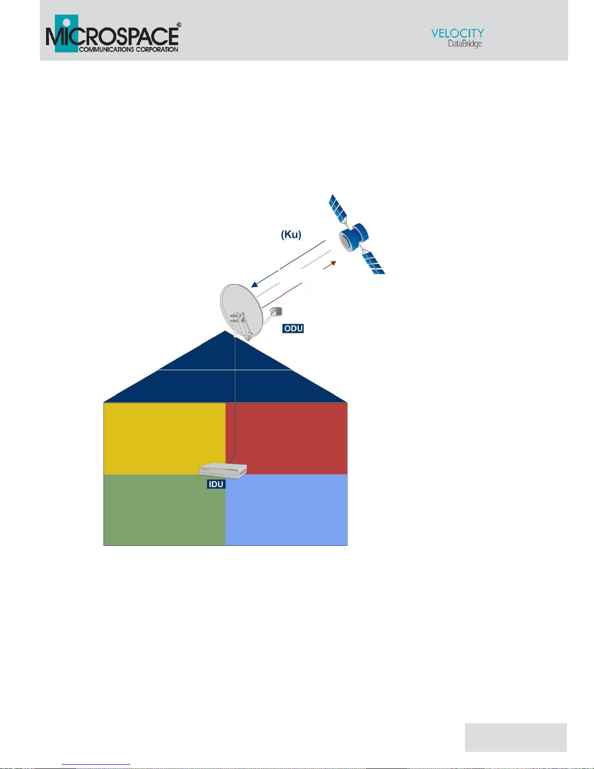
3. GENERAL DESCRIPTION.
The VELOCITY DataBridge Terminal is comprised of the following components:
Antenna System. Satellite dish.
ODU: Outdoor unit. Installed at the antenna’s arm.
IDU: Indoor unit. Located inside the building.
Fig.1. General Diagram.
Interactive Satellite Terminal
Page 6
4. COMPONENTS CONTAINED IN THE PACKAGE.
The package contains:
Dish Antenna.
Feed arm and fasteners.
Indoor unit.
Outdoor unit (with LNB).
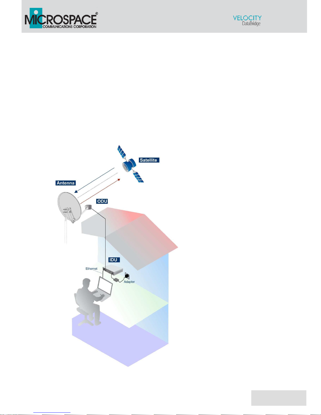
5. INSTALLATION OVERVIEW.
The image below shows a typical installation.
Fig.2. Installation Overview.
Interactive Satellite Terminal
Page 7
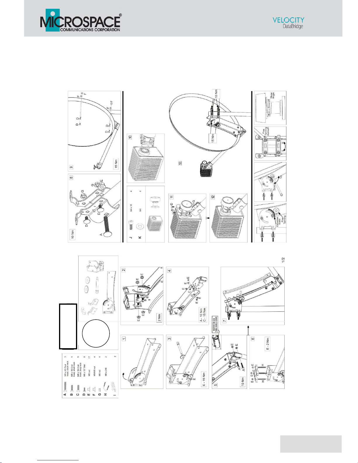
6. ANTENNA SYSTEM.
Satellite antenna with a diameter of 75cm and a masthead assembly,
including an Outdoor Unit.
Antenna components
VF075SMART
Interactive Satellite Terminal
Page 8
6.1. Technical features.
DOWNLINK
Satellite Reception
Interactive Services
Broadcast Services
Standard
DVB-S/S2
Ku Band
High Band: 11.7 Ghz … 12.75 GHz
UPLINK
Satellite Transmission
IP Data for interactive applications.
Standard
F-SIM
Ku Band
13.75 Ghz … 14.5 GHz.
Maximum output Power
31.5 dBm
GENERAL
Azimuth Angle Range
360º
Elevation Angle Range
10 to 90
Feed Interface Diameter
23 mm adapter
Mast Pipe interface
32mm – 60 mm
ENVIRONMENTAL REQUIREMENTS
Operational Wind loading
48 MPH
Survival Windload
89 MPH
Destructive Windload
134 MPH
The Outdoor Unit connects to the Indoor Unit with RG6 coax (supplied by installer.)
This cable length should be less than 250 feet.
Interactive Satellite Terminal
Page 9
Ku Dish.
Antenna Parameters
Type
Offset
Offset
20,8º
Reflector Diameter
750 x 802 mm
Focal Distance
585 mm
F/D Ratio
0,78
Frequency Range (GHz)
RX: 10,7 - 12,75 GHz
TX: 13,75 – 14,5 GHz
Reflector material
Galvanized Steel
Reflector Thickness
0,65 mm
Polarization
Linear/Circular
Gain @ 14,50 GHz
39,4 dBi
Elevation Adjustment Range
10º to 90º
Azimuth Adjustment Range
360º
Mast Pipe Interface
40 – 60 mm
Feed Interface Diameter
23 mm adapter
77 (IEC1114-2 Standard)
77 (IEC1114-2 Standard)
Survival Windload
89 MPH
Destructive Windload
134 MPH
Interactive Satellite Terminal
Page 10
6.2. Setting up the antenna.
Installation of the antenna includes the
following steps:
Step 1: Choosing a suitable location.
Step 2: Mounting the antenna pole.
Step 3: Mounting the antenna.
Step 4: Pointing the antenna.
Do not stand in front of the LNB or the antenna dish during pointing. Keep
the space between the LNB and the antenna dish clear.
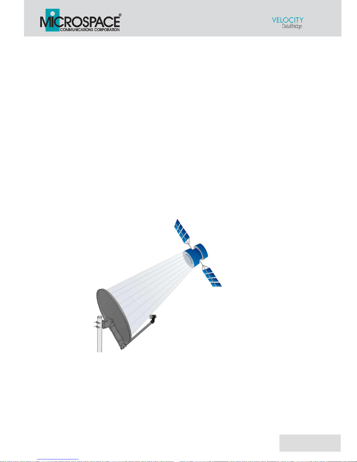
6.2.1. Step 1: Choosing a suitable location.
When setting up the antenna base, take account of the
orientation the antenna must have.
The antenna needs a clear, unobstructed view towards the
satellite located at 113W° (without any buildings, trees - that may
block the signal).
Fig.3. Antenna system.
The antenna must have clear line of sight and no obstruction
blocking the path between the antenna and the satellite.
 Loading...