

Page 1

Microsound Systems
MF A02
MF A08
MF A20
Apartment Intercom System
Instruction Manual
Page 2

Contents
1.
General Description .................................................................................................................................3
1.1. Features ............................................................................................................................................3
2. Operating .................................................................................................................................................3
2.1. Calling .............................................................................................................................................3
3. Installation ...............................................................................................................................................3
3.1. Handset connections ........................................................................................................................3
3.2. Door Station Connections ................................................................................................................4
3.3. Power Supply Connections ..............................................................................................................4
4. Audio level adjustments ..........................................................................................................................4
5. Technical Information .............................................................................................................................4
5.1. Cable requirements ..........................................................................................................................4
5.2. Door Station .....................................................................................................................................4
5.3. Handset ............................................................................................................................................4
6. First Line Service.....................................................................................................................................4
6.1. Test Voltages ...................................................................................................................................5
6.2. Operation .........................................................................................................................................5
7. Wiring ......................................................................................................................................................5
8. Guarantee .................................................................................................................................................5
16 April 2008
MFA0X.doc 16-04-08
Page 2 of 6
Page 3

1. General Description
1.1. Features
1. One door station or two door stations with switcher.
2. 2 to 20 handsets.
3. 3 common wires through out plus 1 call wire per handset.
4. Two handsets on one number.
5. The system is lightning protected.
6. Door station is surface mounted and weather protected.
2. Operating
2.1. Calling
1. Press required number.
2. The calling tone will be heard softly from the loud speaker.
3. When the handset is lifted there will be open communication to the handset.
4. If the person wishes to let you in they can push the “Door release button”.
5. As soon as the handset is replaced the call is cancelled.
3. Installation
1. Three common wires from the door station to the handset plus one call wire per handset. A
core each for Ground, Receive (Rx) and transmit (Tx). Twisted pair cable must not be used,
rather a plain ten core cable 0.8mm. Fire Alarm cable must be used, which has an overall
mylor screen.
2. The screen must be earthed at one point to protect against lightning. Where a main cable run
enters a block of units it can be reduced in size to a 0,5 mm cable, to make termination at the
handsets easy.
3. All junction boxes must have isolation points to allow for easy disconnection of cable runs.
4. All cables must be marked.
5. The door station must also be wired to the door release strike and power supply. A separate
15v DC power supply is required per system. The power supply must have built in lighting
protection or a lighting protection plug.
6. If two door stations are installed a MFAS2 switcher must be used between all the handsets and
the door stations. The switcher requires +15V and GND. The main door station must be
connected to D/S 1 the secondary door station to D/S 2 and all the handsets to H/S. The
individual call wires from both door stations must be common together and then wired to the
handsets. D/S 1 is normally connected to all the handsets. If any button on D/S2 is pressed the
busy line will cause the switcher to change over to D/S2 for predetermined time set by SW1 in
5 second binary steps. Minimum time 5 seconds maximum time 80 seconds.
3.1. Handset connections
Microsound handset (RJ 11)
1 Individual call wire. ( + )
2 Gnd Common Ground from door station. (
3 Rx Common Receive from door station. ( R )
4 Tx Common Transmit from door station. ( T )
MFA0X.doc 16-04-08
- )
Page 3 of 6
Page 4

3.2. Door Station Connections
1. +15vdc Power from power supply
2. Gnd Ground from power supply
3. DS1 Door strike. Normally Open contact
4. DS2 Door strike
5. Gnd To handset. Common to all handsets
6. Tx Transmit to handset. Common to all handsets
7. Rx Receive to handset. Common to all handsets
3.3. Power Supply Connections
1. +15vdc Connect to door stations
2. Gnd Connect to door stations
3. Neutral Mains (220vac)
4. Live Mains (220vac)
4. Audio level adjustments
1. TX adjust level from the door station to the handsets.
2. RX adjusts level from the handsets to the door station.
3. These adjustments are best set when the complex system is installed.
5. Technical Information
5.1. Cable requirements
Three common wires to each handset plus one call wire per handset. Maximum accumulated
length 500 metres using 0.8mm fire alarm cable.
5.2. Door Station
MFA02 size : 136mm high x 101mm wide x 80/60mm deep
MFA08size : 161mm high x 156mm wide x 80/55mm deep
MFA20 size : 292mm high x 156mm wide x 80/55mm deep
Mounting : Surface.
Finish : Weather proof box constructed of mild steel and powder coated. The
front is constructed of anodised aluminium.
Power: 15 vdc 70 ma
5.3. Handset
Size : 215 mm x 96 mm wide x 65 mm high.
Power : 15 vdc 10 ma (idle).
15 ma (ringing)
6. First Line Service
MFA0X.doc 16-04-08
Page 4 of 6
Page 5
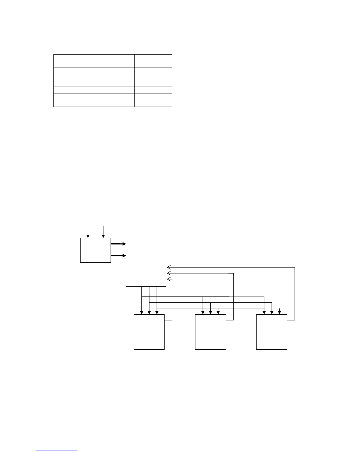
6.1. Test Voltages
RX
Green
TX
Yellow
Idle 6 6
Handset up 1 6
Speech 1 6
Door release 1 0
Handset down 6 6
6.2. Operation
TX line
1. TX audio.
2. Detects when the door release button is being pressed.
RX line
1. RX audio.
CALL
1. 14v to call handsets.
GND
1. Ground to all handsets.
7. Wiring
MFAPSU MFA02/08/20
GN TX RX
CALL
CALL
GND
TX
RX
MFAHS + MFAHS + MFAHS +
Basic layout ( one door station )
8. Guarantee
The MFA02/08/20 is guaranteed by the manufacture for a period of six months from the date of
delivery against faulty components and faulty workmanship (ex factory).
MFA0X.doc 16-04-08
Page 5 of 6
Page 6

Manufactured by:
Microsound Systems cc
P.O. Box 38220
Booysens 2016
Phone 011 493-2424 Fax 011 493-0347
Email: [email protected]
web: http://www.microsound.co.za
Distributed by: Installed by:
MFA0X.doc 16-04-08
Page 6 of 6
 Loading...