

Page 1

MB415
OFFICE INTERCOM
INSTRUCTION MANUAL
MB415 Intercom Manual 1
Page 2

Contents
1. General Description………………………………………………………………………… 3
2. Features …………………………………………………………………………………….. 3
3. Operating Procedure
a. Call…………………………………………………………………………………….. 3
b. Receiving a call………………………………………………………………………. 3
c. Privacy………………………………………………………………………………… 3
d. Group call……………………………………………………………………………... 3
e. All call …………………………………………………………………………………. 3
4. Master Station Facilities……………………………………………………………………. 4
5. Components Available
a. MB415 Master station………………………………………………………………… 4
b. MB415WMB Wall bracket……………………………………………………………. 4
c. MB415PSU Power supply……………………………………………………………. 4
d. MB415DRS Door Station 2 button………………………………………………….. 4
6. Installation
a. Master station…………………………………………………………………………. 4
b. Socket connection……………………………………………………………………. 5
c. MB415PSU Power supply……………………………………………………………. 5
d. MB415DRS Door station 2 button…………………………………………………... 5
e. MB415WMB Wall bracket……………………………………………………………. 6
7. Technical specification……………………………………………………………………… 6
MB415 Intercom Manual 2
Page 3

1. General Description
The MB415 is a low cost master-to-master simplex intercom system. It is a compact
loud speaking system with open voice with handset mode. The system does not have a
central controller, only a central power supply.
2. Features
· Master to Master (maximum 16)
· Master to Public Address (PA)
· Door Station to Master
· Loud speaking
· Handset mode
· All call
· Group call
· Private speech link
· Privacy on Masters
· Priority cancel
· Auto time-out
· Automatic call tone
· Desk or wall mounting.
3. Operating Procedure
a. Call:
Dial the two digit number of the required intercom station, as each button is
pressed a confirmation tone will be heard. When the call is connected, the audio
from the called master will be heard. Press the “*” button to talk and release to
listen.
b. Receiving a call:
Hands free reply back. You can go into handset mode by pressing “7” and lifting
the unit to your ear. The receiving station can also cancel the call by pressing the
“#” button.
c. Privacy:
Press “8”. The red LED will light up indicating that your microphone is muted. If
you are called in this mode both parties will hear a ‘peep-peep’. You will hear the
caller but the caller will not hear you. If you wish to reply, press “8” again.
d. Group Call:
Dial “91” and talk, press “#” to cancel when complete.
e. All Call:
Dial “99” and talk, press “#” to cancel when complete.
MB415 Intercom Manual 3
Page 4

4. Master Station Facilities
· Door release. For Door Station press “5”
· Handset mode. Dial “7”
· Privacy. Dial “8”
· Master Stations numbers. Dial 01 to 16
· Group call. Dial “91”
· All call. Dial “99”
· Press to talk. Press “*”
· Cancel. Press “#”
· System busy – Green LED
· Master in privacy mode – Red LED.
5. Components Available
a. MB415 Master Station:
Described above. Comes with 2 metres of cable and a surface mount socket and
plug.
b. MB415WMB Wall Bracket:
Spring metal clip for wall mounting Masters.
c. MB415PSU Power Supply:
15V DC 4Amps supply with lighting protection and termination PCB. Comes
complete with 1 metre of cable and surface mounted socket and plug.
d. MB415DRS Door Station 2 Button:
Surface mount with call to two different Masters and door release.
6. Installation
The system works on 4 common cores of 0.5mm diameter square Cabtyre cable. The 4
cores must be connected to the power supply, master stations and door station (if
applicable). Maximum cable length is 200 metres on 0.5mm diameter cable. The
MB415 power supply must be used as it has lightning protection and a termination PCB
built-in. The power supply should always be positioned in the centre of the cable run.
The 4 cores carry +15VDC, GND, A audio & B audio to all units. All the masters, power
supply and door station are supplied with a RJ11 surface socket marked B, A, -, + and
all are wired the same way into the 4 core Cabtyre. The units will then plug into the
sockets. When all the sockets are wired, first plug in the power supply and switch on.
Measure the voltage at each socket with reference to GND (+) A and B must be +5V
and +, 15V. The masters can then be plugged in.
a. Master Station
First terminate the socket into the cable run as per colour code. Open the master
station by removing the four screws under the feet. Inside is a six way DIP switch
for setting the master station intercom numbers, in or out of group call and if it
has priority cancel or not.
MB415 Intercom Manual 4
Page 5
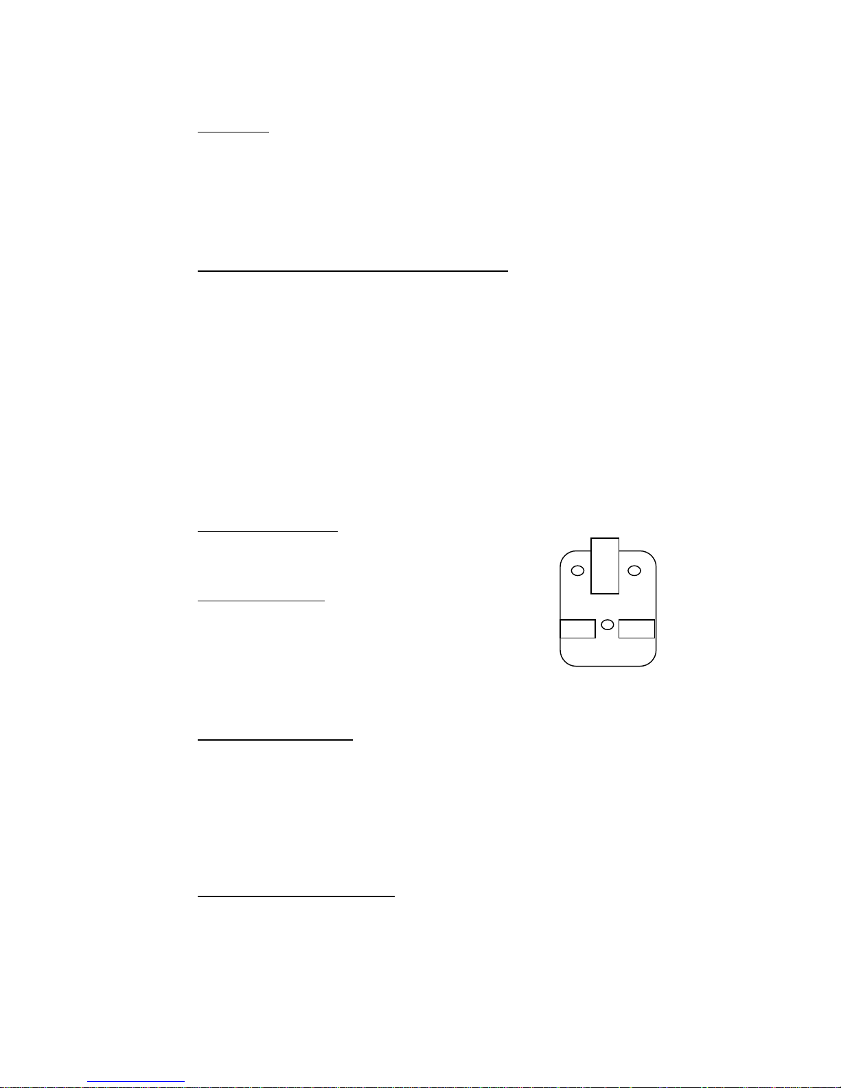
B A - +
Dip Switch
Intercom number: On = decimal 1
Intercom number: On = decimal 2
Intercom number: On = decimal 4
Intercom number: On = decimal 8
Group call: On = in group 1
Priority cancel: On = priority cancel on.
Example of intercom number 11 switch set up:
Dip switch: 1 On = 1
2 On = 2
3 Off = 0
4 On = 8
There are two preset pots, the rear one can be adjusted to set the speaker
volume and the front one the earphone volume.
Close the master replacing the screws and feet. Plug the master in and switch
the power on. The green LED will flash 11 times confirming the station number.
Wait 30 seconds before using the system to allow all the masters to indicate their
respective numbers.
Current consumption:
50MA – Idle
100MA – Maximum
b. Socket Connection
+15VDC (+15VCD) +
Ground (Ground) A audio (+5VCD) A
MB415
B audio (+5VCD) B
In noisy environments cable with an overall screen should be used.
c. MB415P Power Supply
The power supply is a 220VAC to 15VDC at 3Amps regulated supply. It has
lighting protection on the primary and secondary voltages, and on the two audio
lines. It also provides a termination to the 5VDC for the two audio lines.
The power supply comes with a meter of cable and a surface socket and plug, for
easy and neat installation. The power supply must always be connected into
centre of the cable run.
d. MB415 Door Station 2 Button
The door station is a mild steel surface mount box with an aluminium front. The
2 buttons can be factory programmed to call Master 1, 2, 3, 4 or All Master Call.
Normally programmed button 1 calls master 1, button 2 calls All Masters.
MB415 Intercom Manual 5
Page 6

The unit is connected to the 4 core Cabtyre via the socket supplied the same as
a master station. It is factory programmed number 21.
When the door station is communicating with a master the master can press 5 to
enable the door release relay in the door station, which is a potential free nor.
Open contact.
e. MB415WMB Wall Bracket
The wall bracket must be mounted onto the surface wall socket cover, not
directly onto the wall.
7. Technical Specifications
Master stations 16 maximum
Speech links 1
Audio Unbalanced
Audio level + - 1V peak to peak
Signalling DTMF tones
Sign level + - 1V peak to peak
Cabling 4 core 0.5mm diameter square Cabtyre
Cable length 200m maximum
Power supply 15VDC regulated with audio termination
Current drain 50MA idle per master
100MA maximum
Audio output 500MW maximum
Frequency range 500 – 5000Hz
Dimensions 70mm width
60mm height maximum
210mm length
Weight 350grams
Material ABS plastic
Colour Cream
Cable length 1meter + 200mm curly cord
Plug & socket 4 way telecom connector.
Guarantee
The MB415 Office Intercom is guaranteed by the manufacturer for a period of twelve months
from the date of delivery against faulty components and faulty workmanship (ex factory).
Manufactured by:
Microsound Systems CC
P.O. Box 38220
Booysens
2016
South Africa
Tel: 011 493 2424 Fax: 011 493 0347
Email: [email protected]
Web: www.microsound.co.za
MB415 Intercom Manual 6
 Loading...