

Page 1
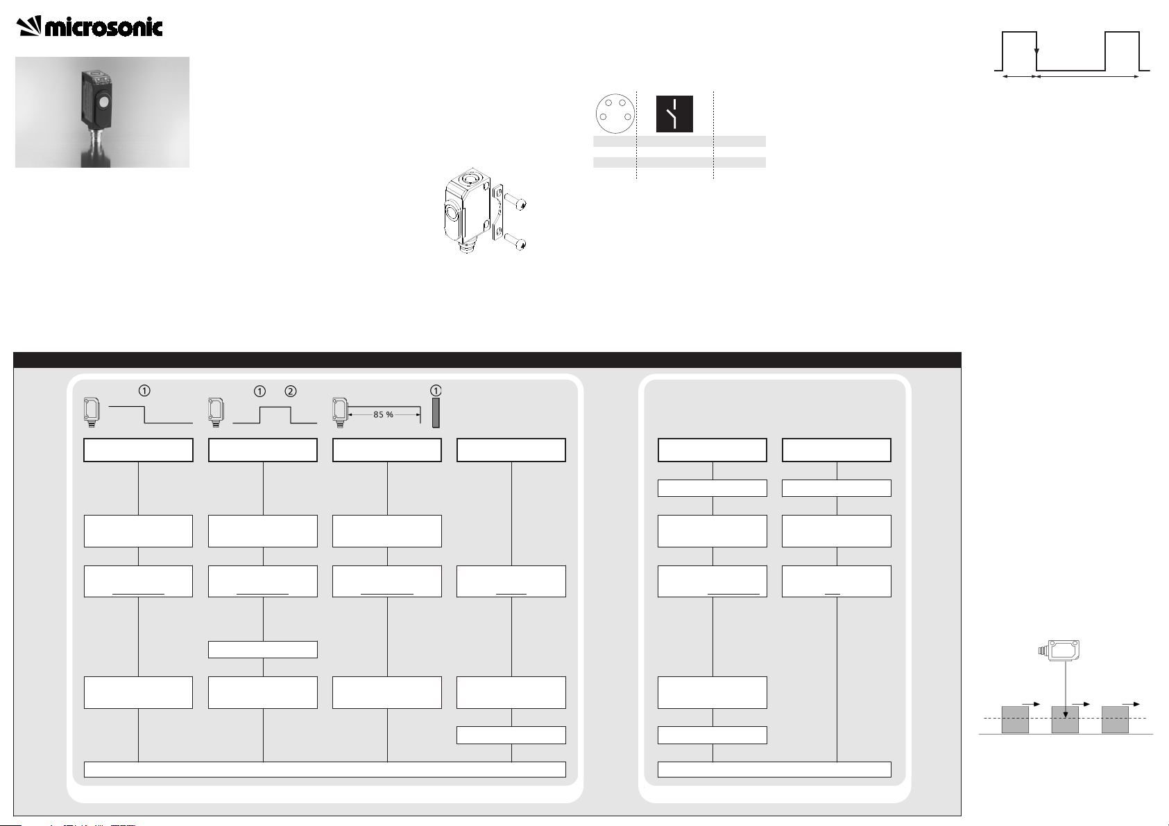
Sensor adjustment with Teach-in procedure
Set detect point
Place object at position
Press push-button for about
3 s until LEDs flash
simultaneously
both LEDs:
flash
mutually
Press push-button for
about 1 s
Set window mode
Place object at position
Press push-button for about
3 s until LEDs flash
simultaneously
both LEDs:
Place object at position
Press push-button for
about 1 s
flash
mutually
Set two way reflective
barrier
Set NOC/NCC
Enable/disable Teach-in
push-button
Switch off power supply
Place reflector at position
Press push-button for about
3 s until LEDs flash
simultaneously
Press button for about 13 s
until LEDs flash
mutually
both LEDs:
flash
mutually
Press push-button for
about 10 s
green LED:
yellow LED:
To change output characte-
ristic press push-button
for about 1 s
While pressing the push-
button switch on power
supply
Keep push-button pressed
for about 3 s until both
LEDs flash simultaneously
flashes
on: NOC
off: NCC
green LED:
yellow LED:
flashes
on: push-button
enabled
off: push-button
disabled
To enable/disable Teach-in
press push-button
for about 1 s
Reset to factory setting
Switch off power supply
While pressing the push-
button switch on power
supply
Keep push-button pressed
for about 13 s until both
LEDs stop
flashing
Normal operating mode
Wait for 10 s
Wait for 10 s
Normal operating mode
Operating Instructions
Ultrasonic Sensors
1
3
colour
+U
B
-U
B
brown
blue
4
2
D
Sync
black
white
143
2
Sensor disabled Sensor disabled
Start
+U
B
-U
B
ti
tp
Further settings
Set switched output
zws-7/CD/QS zws-7/CE/QS
zws-15/CD/5ms.a zws-15/CE/5ms.a
Fast ultrasonic proximity switch
with one switched output
Product Description
The zws sensor offers a non-contact
measurement of the distance to an
object which must be positioned
within the sensor’s detection zone.
The switched output is set in dependence of the adjusted detect distance.
Due to the short response time and
the high switching frequency these
zws sensors are applicable to the detection of quick processes. For the
zws-7, the faster variant, please see
the notes for installation and operation.
Via the push-button, the detect distance and operating mode can be
adjusted (teach-in). Two LEDs indicate operation and the state of the
switched output.
Safety Notes
Read the operating instructions
prior to start-up.
Connection, installation and
adjustment works may only be
carried out by expert personnel.
No safety component in accor-
dance with the EU Machine Directive.
Installation
Mount the sensor at the installa-
tion site with the aid of the
enclosed mounting plate.
Maximum torque of attachment
screw: 0,5 Nm
Fig. 1: Attachment with mounting plate
Connect a connection cable to the
M8 device plug.
Avoid mechanical load on the con-
nector.
Start-Up
Connect the power supply.
Carry out the adjustment in
accordance with the diagram.
Fig. 2: Pin assignment with view onto sensor
plug and colour coding of the
microsonic connection cable
Factory Setting
Operation with one detect point
Switched output on NOC
Detect points at operating range
Operating modes
Three operating modes are available
for the switched output:
Operation with one detect point
The switched output is set if the object falls below the set detect point.
Window mode
The switched output is set if the object is within the set window margins.
Two-way reflective barrier
The switched output is set if the object is between sensor and reflector.
Synchronization
You can synchronize as many sensors
as you like.
Apply a square-wave signal to the
sync-input with pulse width ti and
repetition rate tp (Fig.3 and
technical data).
Fig.3: External synchronization signal
A high level on the sync-input will
deactivate the sensor.
Checking operation mode
In normal mode shortly press the
push-button.
The green LED stops shining for one
second, then it will show the current
operating mode:
1 x flashing = operation with one
switching point
2 x flashing = window mode
3 x flashing = reflective barrier
After a break of 3 s the green LED
shows the output function:
1 x flashing = NOC
2 x flashing = NCC
Maintenance
microsonic sensors are maintenancefree. In case of excess caked-on dirt
we recommend cleaning the white
sensor surface
Notes
The zws sensor has a blind zone,
within which distance measurements are not possible.
In the normal operating mode, an il-
luminated yellow LED signals the
switched output is switched
through.
The sensor got to know the
distance to the object at the teachin stage. For objects that move into
the sound field from the side, an 810 % greater distance should be
set for reliable object detection by
the sensor.
Fig. 4: Setting the switching point
The zws-7 has a very short measu-
rement cycle time of only 2 ms.
Under unfavourable conditions
this can lead to the sensor wrongly
Page 2
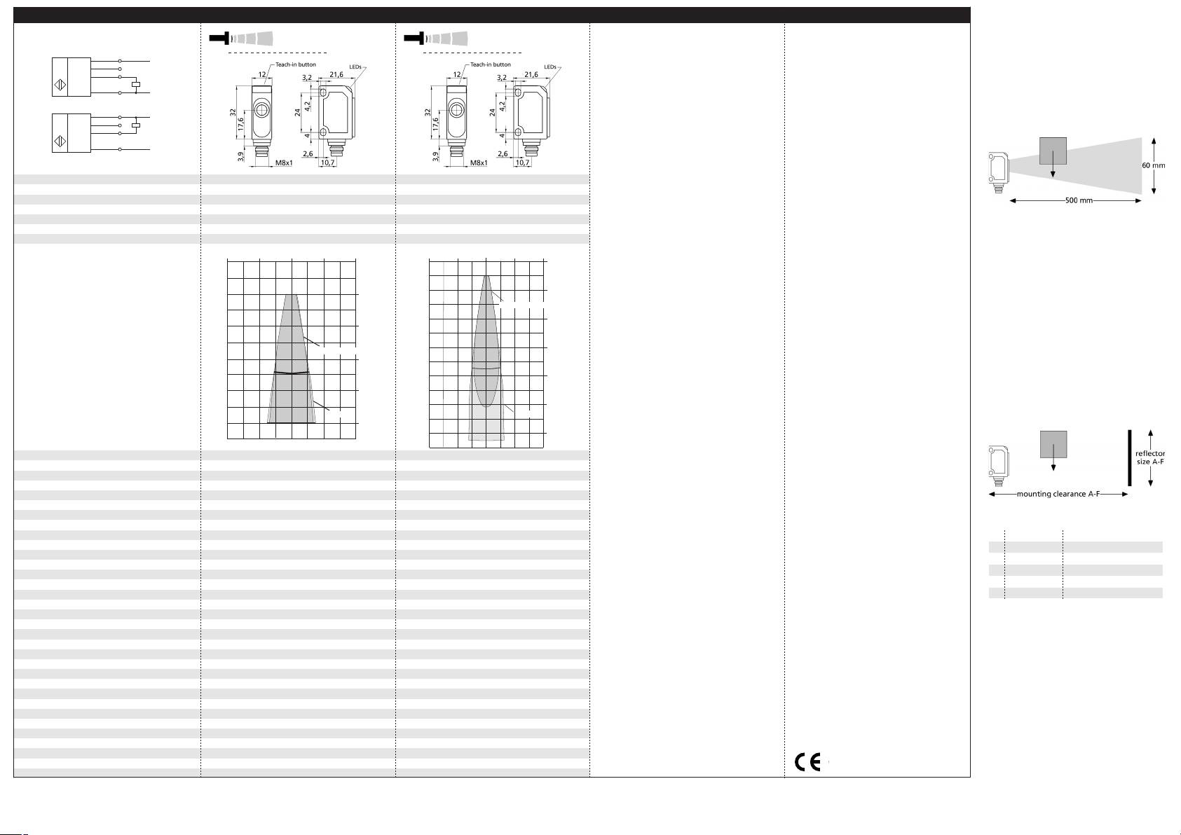
Technical data
Blind zone
Operating range
Maximum range
Angle of beam spread
20 mm
70 mm
20 mm
150 mm
100 mm
See detection zone
250 mm
See detection zone
Transducer frequency
Resolution, sampling rate
Reproducibility
Detection zones
for different objects:
The dark grey areas are determined
with a thin round bar (10 mm dia.)
and indicate the typical operating range
of a sensor. In order to obtain the light grey
areas, a plate (100 x 100 mm) is introduced
into the beam spread from the side.
In doing so, the optimum angle between
plate and sensor is always employed.
This therefore indicates the maximum
detection zone of the sensor.
It is not possible to evaluate ultrasonic
reflections outside this area.
380 kHz
0,20 mm
380 kHz
0,20 mm
± 0,15 %
± 0,15 %
Accuracy
Operating voltage U
B
Voltage ripple
No-load current consumption
Temperature drift 0,17 % / °C
20 - 30 V DC, reverse polarity protection
Temperature drift 0,17 % / °C
20 - 30 V DC, reverse polarity protection
±10 %
< 30 mA
±10 %
< 30 mA
Housing
Class of protection to EN 60 529
ABS
ultrasonic transducer: polyurethane foam,
ABS
ultrasonic transducer: polyurethane foam,
epoxy resin with glass content
IP 67
epoxy resin with glass content
IP 67
Type of connection
Controls
Indicators
4-pin M8 initiator plug
Yes, Teach-in push-button
4-pin M8 initiator plug
Yes, Teach-in push-button
LED green (operation)
LED yellow (state of output)
LED green (operation)
LED yellow (state of output)
Programmable
Synchronisation
Pulse width synchronization signal t
p
Repetition rate synchronization signal t
p
No
Yes, external
No
Yes, external
> 150 µs
2 ms < tp < 1 s
> 150 µs
5 ms < tp < 1 s
Operating temperature
Storage temperature
Weight
Switching hysteresis
-25°C to +70°C
-40°C to +85°C
-25°C to +70°C
-40°C to +85°C
10 g
2 mm
10 g
2 mm
Switching frequency
Response time
Switch-off delay time
Time delay before availability
250 Hz
< 3 ms
100 Hz
< 7 ms
< 3 ms
< 300 ms
< 7 ms
< 300 ms
Norm conformity
Order no.
Switched output
EN 60947-5-2
EN 60947-5-2
zws-7/CD/QS
pnp, UB-2 V, I
max
= 200 mA
zws-15/CD/5ms.a
pnp, UB-2 V, I
max
= 200 mA
Order no.
Switched output
switchable NOC/NCC, short-circuit-proof
switchable NOC/NCC, short-circuit-proof
zws-7/CE/QS
npn, -UB+2 V, I
max
= 200 mA
zws-15/CE/5ms.a
npn, -UB+2 V, I
max
= 200 mA
switchable NOC/NCC, short-circuit-proof switchable NOC/NCC, short-circuit-proof
1
2
4
3
+U
B
-U
B
Sync
U
1
2
4
3
+U
B
-U
B
Sync
U
1 pnp switched output
1 npn switched output
zws-7...
zws-15...
2 cm 0 cm 2 cm
0 cm
2 cm
4 cm
6 cm
7 cm
8 cm
10 cm
Plate
Round bar ø 10 mm
4 cm 4 cm
8 cm 4 cm 0 cm 4 cm 8 cm
0 cm
4 cm
8 cm
12 cm
16 cm
20 cm
24 cm
Round bar ø 10 mm
Plate
microsonic GmbH • Hauert 16 • D-44227 Dortmund • Tel: +49 2 31 / 97 51 51-0 • Fax: +49 2 31 / 97 51 51-51 • E-Mail: info@microsonic.de • www.microsonic.de
The content of this document is subject to technical changes. Specifications in this document are presented in a descriptive way only. They do not warrant any product features.
MV-DO-085271-408188
responding to echoes from existing measurements. To avoid this,
there has to be an unobstructed
space extending to a depth of 500
mm in front of the sensor. Only
the objects to be detected are to
be within the sensor's 20-100 mm
operating area.
Fig. 5: Unobstructed space in front of the
sensor
With the zws-7, it is vital that the
objects to be detected enter the
sound fields from the sides..
If the unobstructed 500 mm space
cannot be provided or should the
sensor be used in the «Two-way
reflective barrier» mode, then a
plane reflector at a specific distance to the sensor must be fitted.
The size of the reflector and its
working clearance from the sensor
can be taken from the table in
Fig.7.
Fig. 6: Sensor/reflector working clearance
Fig. 7: Working clearance and reflector sizes
In the »Two-way reflective barrier«
operating mode, the object has to
be within the range of 0-85 % of
the set distance.
The zws-7 sensor has no tempera-
ture compensation.
If the push-button is not pressed
for 2 minutes during the teach-in
setting, the settings made hitherto
are deleted.
The sensor can be reset to its fac-
tory setting.
A
B
C
D
E
F
366 mm 60 mm x 60 mm
194 mm
137 mm
60 mm x 60 mm
50 mm x 50 mm
108 mm
91 mm
40 mm x 40 mm
40 mm x 40 mm
79 mm 30 mm x 30 mm
89/336/EEC
 Loading...