

Page 1
Product Description
Set switched output
Further settings
Ultrasonic Sensors
The sks sensor offers a non-contact
measurement of the distance to an
object which must be positioned
within the sensor’s detection zone.
The switched output is set in dependence of the adjusted detect distance.
Via the push-button, the detect distance and operating mode can be
adjusted (teach-in). Two LEDs indicate operation and the state of the
switched output.
The output function is changeable
Operating Instructions
sks-15/D sks-15/E
sks-15/CD sks-15/CE
from NOC to NCC.
Ultrasonic proximity switch with
one switched output
Sensor adjustment with Teach-in procedure
Safety Notes
■ Read the operating instructions
prior to start-up.
■ Connection, installation and
adjustment works may only be
carried out by expert personnel.
■ No safety component in
accordance with the EU Machine
Directive
Proper use
sks ultrasonic sensors are used for
non-contact detection of objects.
Installation
■ Mount the sensor at the installa-
tion site.
Maximum torque: 0,5 Nm
■ Connect a connection cable to the
M8 device plug.
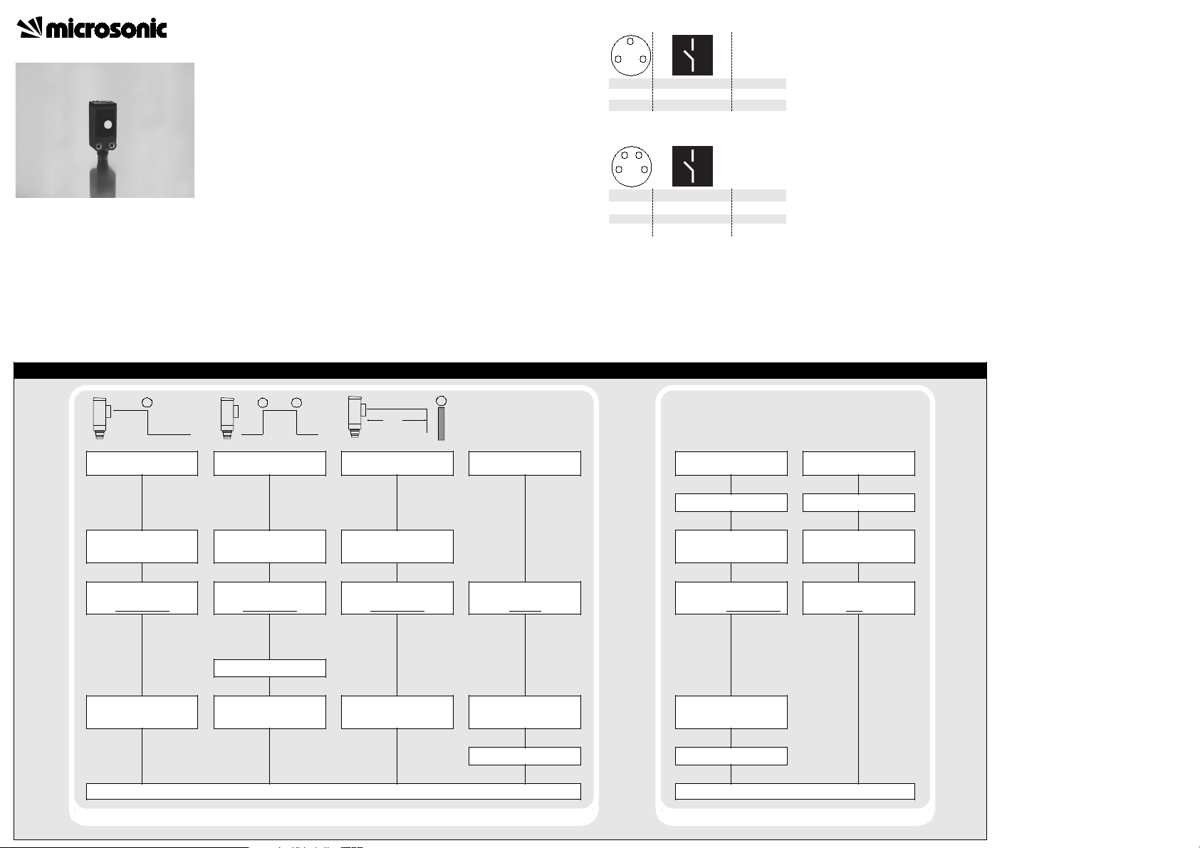
3-pin initiator plug
143
1
3
4
+U
-U
D
colour
brown
B
blue
B
black
4-pin initiator plug
2
143
1
3
4
2
Fig. 2: Pin assignment with view onto sensor
plug and colour coding of the
microsonic connection cable
+U
-U
D
Com
colour
brown
B
blue
B
black
white
Start-Up
■ Connect the power supply.
■ Carry out the adjustment in
accordance with the diagram.
Factory Setting
■ Operation with one detect point
■ Switched output on NOC
■ Detect points at operating range
Operating modes
Three operating modes are available
for the switched output:
■ Operation with one detect point
The switched output is set if the object falls below the set detect point.
■ Window mode
The switched output is set if the object is within the set window margins.
■ Two-way reflective barrier
The switched output is set if the object is between sensor and reflector.
Checking operation mode
■ In normal mode shortly press the
push-button.
The green LED stops shining for one
second, then it will show the current
operation mode:
1 x flashing = operation with one
switching point
2 x flashing = window mode
3 x flashing = reflective barrier
After a break of 3 s the green LED
shows the output function:
1 x flashing = NOC
2 x flashing = NCC
Maintenance
microsonic sensors are maintenancefree. In case of excess caked-on dirt
we recommend cleaning the white
sensor surface
1
Set detect point
Place object at position ➀
Press push-button for about
3 s until LEDs flash
simultaneously
both LEDs: flash
Press push-button for
about 1 s
mutually
2
1
Set window mode
Place object at position ➀
Press push-button for about
3 s until LEDs flash
simultaneously
both LEDs:
Place object at position ➁
Press push-button for
about 1 s
flash
mutually
Normal operating mode
85 %
Set two way reflective
barrier
Place reflector at position ➀
Press push-button for about
3 s until LEDs flash
simultaneously
both LEDs: flash
Press push-button for
about 10 s
mutually
1
Press button for about 13 s
green LED:
yellow LED:
To change output characte-
ristic press push-button
Set NOC/NCC
until LEDs flash
mutually
flashes
on: NOC
off: NCC
for about 1 s
Wait for 10 s Wait for 10 s
Enable/disable Teach-in
push-button
Switch off power supply
While pressing the push-
button switch on power
supply
Keep push-button pressed
for about 3 s until both
LEDs flash simultaneously
green LED:
yellow LED:
To enable/disable Teach-in
press push-button
for about 1 s
Keep push-button pressed
flashes
on: push-button
enabled
off: push-button
disabled
Normal operating mode
Reset to factory setting
Switch off power supply
While pressing the push-
button switch on power
supply
for about 13 s until both
LEDs stop
flashing
Notes
■ sks-15/CD and sks-15/CE sensors
have internal temperature compensation. Because the sensors
heat up on their own, the temperature compensation reaches its
optimum working point after approximatly 30 minutes of operation.
The sensors sks-15/D and sks-15/E
have no temperature compensation.
■ The sks sensor has a blind zone,
within which distance measurements are not possible.
■ In the normal operating mode, an il-
luminated yellow LED signals the
switched output is switched
through.
■ If the object to be sensed moves
into the detection area from the
side, the switching distance should
be set 8-10 % further than the desired switch point to obtain a reliable object detection.
If the object moves towards the
sensor (e.g. level control) the detect point can be taught to the actual distance at which the sensor
has to switch the output.
Page 2
Technical data
g hy
y
1
2
U
4
3
1 pnp switched output
1
2
U
4
3
1 npn switched output
Resolution, sampling rate
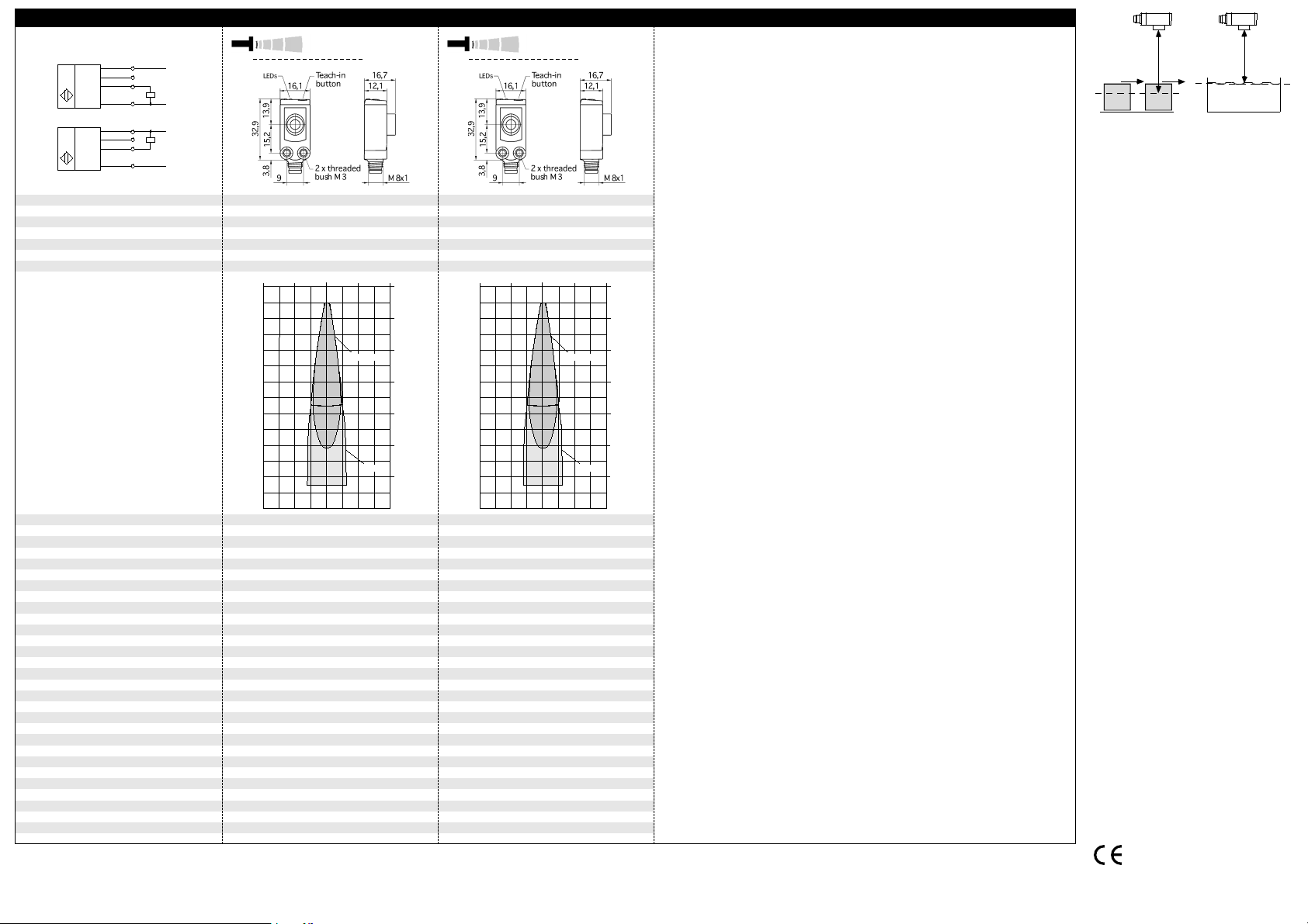
The dark grey areas are determined
with a thin round bar (10 mm dia.)
and indicate the typical operating range
of a sensor. In order to obtain the light grey
areas, a plate (100 x 100 mm) is introduced
into the beam spread from the side.
In doing so, the optimum angle between
plate and sensor is always employed.
This therefore indicates the maximum
detection zone of the sensor.
It is not possible to evaluate ultrasonic
reflections outside this area.
+U
B
(Com)
D
-U
B
+U
B
(Com)
E
-U
B
Blind zone
Operating range
Maximum range
Angle of beam spread
Transducer frequency
Reproducibility
Detection zones
for different objects:
sks-15... sks-15...
20 mm
150 mm
250 mm
See detection zone
380 kHz
0,10 mm
± 0,15 % ± 0,15 %
8 cm 4 cm 0 cm 4 cm 8 cm
Round bar
Plate
0 cm
4 cm
8 cm
12 cm
16 cm
20 cm
24 cm
20 mm
150 mm
250 mm
See detection zone
380 kHz
0,10 mm
8 cm 4 cm 0 cm 4 cm 8 cm
Round bar
Plate
0 cm
4 cm
8 cm
12 cm
16 cm
20 cm
24 cm
Object detection Level control
Fig. 4: Set the detect point for different
directions of movement of the object
■
In the »Two-way reflective barrier«
operating mode, the object has to
be within the range of 0-85 % of
the set distance.
■ If the push-button is not pressed
for 10 minutes during the teach-in
setting, the settings made hitherto
are deleted.
■ The sensor can be reset to its fac-
tory setting.
Accuracy
Operating voltage U
No-load current consumption
Class of protection to EN 60 529
Voltage ripple
Type of connection
Indicators
Programmable
Operating temperature
Storage temperature
Switchin
Switching frequenc
Time delay before availability
microsonic GmbH • Hauert 16 • D-44227 Dortmund • Tel: +49 2 31 / 97 51 51-0 • Fax: +49 2 31 / 97 51 51-51 • E-Mail: info@microsonic.de • www.microsonic.de
The content of this document is subject to technical changes. Specifications in this document are presented in a descriptive way only. They do not warrant any product features.
Response time
Norm conformity
Order no.
Switched output
Order no.
Switched output
Temperature drift 0,17 % / °C Temperature drift internal compensated, ≤ 2 %
20 - 30 V DC, reverse polarity protection
B
±10 %
< 30 mA
Housing
ABS
ultrasonic transducer: polyurethane foam,
epoxy resin with glass content
IP 67
3-pin M8 initiator plug
Controls
Yes, Teach-in push-button
LED green (operation)
LED yellow (state of output)
No
-25°C to +70°C
-40°C to +85°C
Weight
8 g
2 mm
steresis
25 Hz
32 ms
< 300 ms
EN 60947-5-2
sks-15/D sks-15/CD
-2 V, I
B
+2 V, I
B
= 200 mA
max
= 200 mA
max
pnp, U
switchable NOC/NCC, short-circuit-proof
sks-15/E sks-15/CE
npn, -U
switchable NOC/NCC, short-circuit-proof
20 - 30 V DC, reverse polarity protection
±10 %
< 30 mA
ABS
ultrasonic transducer: polyurethane foam,
epoxy resin with glass content
IP 67
4-pin M8 initiator plug
Yes, Teach-in push-button
LED green (operation)
LED yellow (state of output)
No
-25°C to +70°C
-40°C to +85°C
8 g
2 mm
25 Hz
32 ms
< 300 ms
EN 60947-5-2
pnp, UB-2 V, I
switchable NOC/NCC, short-circuit-proof
npn, -UB+2 V, I
switchable NOC/NCC, short-circuit-proof
= 200 mA
max
max
= 200 mA
89/336/EEC
MV-DO-074785-187014
 Loading...