

Microsonic pmsplus15/CF/A1, pmsplus25/CF/A1, pmsplus35/CF/A1, pmsplus100/CF/A1 Operating Instructions Manual
Page 1

Operating Instructions
Ultrasonic proximity switch with
one switched output
pms+15/CF/A1
pms+25/CF/A1
pms+35/CF/A1
pms+100/CF/A1
Product description
The pms sensor has a stainless steel
housing and is designed for applications with hygienic requirements.
The ultrasonic transducer surface of
the pms sensors is laminated with a
PTFE film. The transducer itself is
sealed against the housing by a joint
ring.
The pms sensor with D12 adapter
shaft can be fitted in a mounting clip
which meets hygiene standards like
the sensor srew connection BF-pms/
A1.
The special housing design ensures
that any cleaning fluids are able to
run off completely, regardless of the
installation situation.
The pms sensor is ECOLAB certified.
The pms sensor variant D12 adapter
shaft offers a non-contact measure-
Sensor adjustment with Teach-in procedure
Set detect point
– method A
Place object at position
Connect Com for about
3 s to +U
B
Set detect point +8 %
– method B
Place object at position
Connect Com for about
3 s to +U
B
Set window mode
Set two way reflective
barrier
Set NOC/NCC
Place object at position
Install reflector at
position
Connect Com for about
3 s to +U
B
Connect Com for about
3 s to +U
B
Connect Com for about
13 s to +U
B
Reset to factory setting
Switch off operating
voltage
Connect Com to -U
B
Switch on
operating voltage
Keep Com connected to
-U
B
for about 13 s
Connect Com for about
1 s to +U
B
Normal operating mode
Connect Com for about
3 s to +U
B
Place object at position
Connect Com for about
1 s to +U
B
Connect Com for about
10 s to +U
B
To change output
characteristic connect
Com for about 1 s to +U
B
Wait for 10 s
Disconnect Com from -U
B
before switching off supply
voltage
Normal operating mode
ment of the distance to an object
present within the sensors's detection zone. The switched output is set
conditional upon the adjusted detect
distance.
For sensor setting, the accessory
LinkControl adapter LCA-2 is recommended in combination with LinkControl software for Windows©. Alternatively, the sensor can also be set
by Teach-in via pin 2.
The pms sensors are IO-Link-capable
in accordance with IO-Link specification V1.1.
Safety Notes
Read the operating instructions
prior to start-up.
Connection, installation and ad-
justment works should be carried
out by expert personnel only.
No safety component in
accordance with the EU Machine
Directive.
Proper Use
pms ultrasonic sensors are used for
non-contact detection of objects.
The sensor must be mounted in an
EHEDG-approved mounzing clip,
such as the sensor screw connection
BF-pms/A1 for a EHEDG-complaint
use.
Installation
Assemble the sensor and its hygi-
enic D12 sensor screw connection
BF-pms/A1 or an equivalent sensor
mounting clip at the instation location.
Pull sensor cable through the sen-
sor gland, connect it to the M8
sensor plug.
Push the sensor with its shaft into
the sensor screw connection BFms/A1 and adjust (see figure 4-6).
Tighten with lock nut (maximum
tightening torque 12 Nm).
Fig. 1: Pin assignment with view onto sensor
plug and colour coding of the
microsonic connection cables
Start-up
Connect the power supply.
Carry out sensor adjustment with
1
3
colour
+U
B
-U
B
brown
blue
4
2
F
Com
black
white
1
5
2
34
LinkControl or alternatively Teachin procedure in accordance with
the diagram.
Factory Setting
Detect point operation
Switched output on NOC
Detect distance at operating range
Filter at F01
Filter strength at P00
Operating Modes
Three operating modes are available
for the switched output:
Operation with one detect point
The switched output is set when the
object falls below the set detect
point.
Window mode
The switched output is set when the
object is within the set window.
Two-way reflective barrier
The switched output is set when the
object is between sensor and fixed
reflector.
Fig. 2: Assembly distances
Maintenance
microsonic sensors are maintenancefree. For cleaning in areas with hygienic requirements, access to the sensor must be guaranteed from all
sides. Cleaning is permitted up to a
cleaning temperature of 85°C. Do
not use a high-pressure cleaner to
clean the sensor.
Notes
The sensors of the pms family
have a blind zone, within which a
distance measurement is not possible.
If several pms sensors are operated
in a small space, the minimum
mounting for parallel or opposite
pms-15
pms-25
pms-35
≥0.25 m
≥1.30 m
≥0.35 m
≥2.50 m
≥0.40 m
≥2.50 m
pms-100
≥0.70 m
≥4.00 m
Set switched output
Further Settings
HM-1809
Page 2
Technical data
blind zone
operating range
maximum range
angle of beam spread
20 mm
150 mm
30 mm
250 mm
250 mm
see detection zone
350 mm
see detection zone
transducer frequency
resolution
reproducibility
380 kHz
0.069 mm
320 kHz
0.069 mm
± 0.15 %
± 0.15 %
accuracy
operating voltage U
B
voltage ripple
no-load current consumption
±1 % (temperature drift internally compensated)
10 - 30 V DC, reverse polarity protection (Class 2)
±1 % (temperature drift internally compensated)
10 - 30 V DC, reverse polarity protection (Class 2)
±10 %
< 40 mA
±10 %
< 40 mA
housing
ECOLAB
class of protection per EN 60 529
stainless steel 1.4404/316L;
ultrasonic transducer: PTFE, FKM
stainless steel 1.4404/316L;
ultrasonic transducer: PTFE, FKM
norm conformity
type of connection
controls
EN 60947-5-2
EN 60947-5-2
Teach-in via pin 2 (Com)
Teach-in via pin 2 (Com)
programmable
operating temperature
storage temperature
switched output
Teach-in, LinkControl
-25°C to +70°C
Teach-in, LinkControl
-25°C to +70°C
-40°C to +85°C
Push-Pull, UB-3 V, -UB+3 V, I
max
= 100 mA
-40°C to +85°C
Push-Pull, UB-3 V, -UB+3 V, I
max
= 100 mA
switching hysteresis
1)
switching frequency
1)
response time
1)
switchable NOC/NCC, short-circuit-proof
2 mm
switchable NOC/NCC, short-circuit-proof
3 mm
25 Hz
32 ms
25 Hz
32 ms
time delay before availability
1)
weight
order no.
< 300 ms
30 g
< 300 ms
30 g
pms-15/CF/A1
pms-25/CF/A1
1) Can be programmed with LinkControl
65 mm
350 mm
120 mm
1,000 mm
600 mm
see detection zone
1,300 mm
see detection zone
400 kHz
0.069 mm
200 kHz
0.069 mm
± 0.15 %
± 0.15 %
±1 % (temperature drift internally compensated)
10 - 30 V DC, reverse polarity protection (Class 2)
±1 % (temperature drift internally compensated))
10 - 30 V DC, reverse polarity protection (Class 2)
±10 %
< 40 mA
±10 %
< 40 mA
stainless steel 1.4404/316L;
ultrasonic transducer: PTFE, FKM
stainless steel 1.4404/316L;
ultrasonic transducer: PTFE, FKM
EN 60947-5-2
EN 60947-5-2
Teach-in via pin 2 (Com)
Teach-in via pin 2 (Com)
Teach-in, LinkControl
-25°C to +70°C
Teach-in, LinkControl
-25°C to +70°C
-40°C to +85°C
Push-Pull, UB-3 V, -UB+3 V, I
max
= 100 mA
-40°C to +85°C
Push-Pull, UB-3 V, -UB+3 V, I
max
= 100 mA
switchable NOC/NCC, short-circuit-proof
5 mm
switchable NOC/NCC, short-circuit-proof
20 mm
12 Hz
64 ms
10 Hz
80 ms
< 300 ms
30 g
< 300 ms
30 g
pms-35/CF/A1
pms-100/CF/A1
+U
B
-U
B
F
1
2
4
3
Push-Pull output in pnp circuit
U
+U
B
-U
B
F
1
2
4
3
Push-Pull output in npn circiut
U
Com
Com
pms-15...
pms-25...
pms-35...
pms-100...
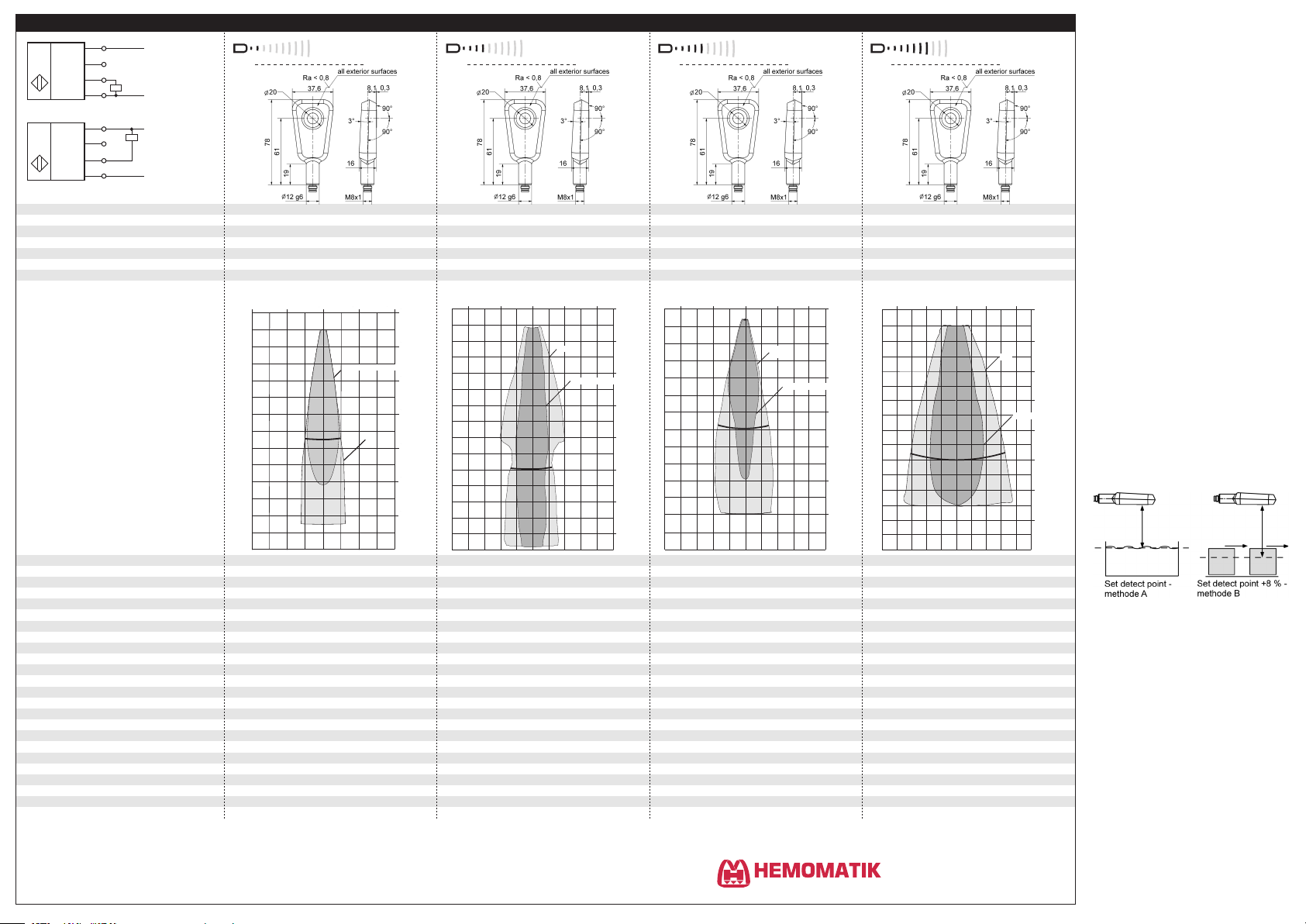
detection zones
The dark grey areas represent the zone
where it is easy to recognise the normal
reflector (round bar). This indicates the typical
operating range of the sensors. The light
grey areas represent the zone where a
very large reflector – for instance a
plate – can still be regognized. The
requirement here is for an optimum
alignment to the sensor. It is not
for different objects:
possible to evaluate ultrasonic
reflections outside this area.
arrangement of the sensors shown
in figure 2 must be maintained.
The pms sensors are equipped
with an internal temperature compensation. Due to the sensors self
heating, the temperature compensation reaches its optimum working-point after approx. 45 seconds
of operation.
In the »Set detect point – method
A« Teach-in procedure the actual
distance to the object is taught to
the sensor as the detect point. If
the object moves towards the
sensor (e.g. with level control) then
the taught distance is the level at
which the sensor has to switch the
output.
4 cm
0 cm
0 cm
0 cm
0 cm
4 cm
4 cm
4 cm
Rohr ø 10 mm
Rohr ø 10 mm
Rohr ø 10 mm
Round bar ø 10 mm
ausgerichtete Platte
ausgerichtete Platte
Plate
8 cm
8 cm
8 cm
8 cm
0 cm
0 cm
0 cm
4 cm
4 cm
4 cm
8 cm
8 cm
8 cm
12 cm
12 cm
12 cm
16 cm
16 cm
16 cm
20 cm
20 cm
20 cm
24 cm
24 cm
24 cm
4 cm
4 cm
8 cm
8 cm
4 cm
4 cm
8 cm
8 cm
10 cm
Plate
Round bar ø 10 mm
0 cm
5 cm
10 cm
15 cm
20 cm
25 cm
30 cm
35 cm
20 cm
10 cm
5 cm
0 cm
5 cm
10 cm
0 cm
10 cm
Plate
Round bar ø 27 mm
20 cm
0 cm
10 cm
20 cm
30 cm
35 cm
40 cm
50 cm
60 cm
0,4 m
0 m
0,2m
Plate
0,4 m
0,6 m
Round bar ø 27 mm
0,8 m
1,0 m
1,0 m
1,3 m
1,4 m
0,4 m
0,2 m
0 m
0,2 m
If the object to be scanned moves
into the detection area from the
side, the »Set detect point +8 % –
method B« Teach-in procedure
should be used. In this way the
switching distance is set 8 % further than the actual measured distance to the object. This ensures a
reliable switching distance even if
the height of the objects varies
slightly.
yes
IP 67
4-pin M8 initiator plug
yes
IP 67
4-pin M8 initiator plug
yes
IP 67
4-pin M8 initiator plug
www.hemomatik.se
yes
IP 67
4-pin M8 initiator plug
Ordertel 08-771 00 04 Växel 08-771 02 20
Orderfax 08-771 62 00 Teknisk 08-771 35 80
Länna, S-142 50 SKOGÅS (Stockholm)
Fig. 4: Setting the detect point for different
directions of movement of the object
The sensor can be reset to its fac-
tory setting (see »Further settings«).
For Teach-in procedure when us-
ing the LinkControl adapter (optional accessory) the additional
adapter 5G/M12-4G/M12/M8 is
needed.
If the sensor is cleaned wet during
operation, all surfaces must be inclined at least 3° from the horizontal alignment so that the cleaning agents can run off completely
(see figure 3).
Page 3
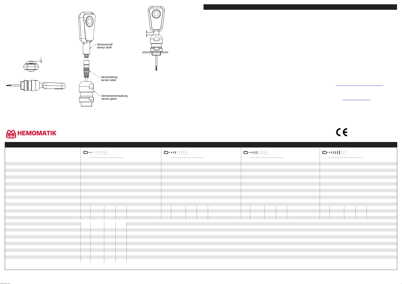
The D12 adapter shaft of the pms
sensor has to stick out at least
6 mm from the screw connection
(see figure 5).
The sealing ring has to fill space
between D12 sensor shaft and cap
nut. Sealing ring should not to be
pressed out excessively from the
shaft gland.
Fig. 3: pms sensor D12-adapter shaft with
sensor screw connection BF-pms/A1,
all surfaces must be inclined at least 3°.
3°min.
Fig. 4:
Mounting of pms sensor with sensor
screw connection BF-pms/A1
Fig. 5: Mounting of pms sensor with sensor
screw connection BF-pms/A1
Mounting accessory
D12 sensor screw connection
BF-pms/A1
Accessory for programming
LinkControl adapter LCA-2
Adapter 5G/M12-4G/M12/M8
6min.
The pms sensors are IO-Link-capable
in accordance with IO-Link specification V1.1.
Note
In IO-Link mode LinkControl and synchronization via pin 2 are not
available.
Smart Sensor Profile
Die pms sensors support the Smart
Sensor Profile. The following profiles
and function classes are integrated:
0x000A - Device Profil:
Digital measuring sensors
0x8000 - Device Identification
0x8001 - Multichannel:
two setpoint switching sensor
0x8003 - Device Diagnosis
0x8004 - Teach Channel
0x800A - Measurement Data Chanel (standard resolution)
Synchronisation in IO-Link Mode
In IO-Link mode each sensor is synchronized on the protocol of the IOLink master. In multiple sensor opera-
tion the sensors are synchronous if
the master protocols are synchronous.
System Commands
With 3 system commands the following settings may be carried out:
Teach-in SP1
Teach-in SP2
Reset sensor to factory settings
SSC1 Configuration
The pms sensor has 5 modes:
Single point (SP1: switching point)
The switched output is activated
when the distance to an object is
under that of the present single
point SP1.
Window (SP1, SP2: window mode)
The switched output is set when
the object is within the set window (SP1, SP2).
Two point (SP1, SP2: hystese
mode)
In hysteresis mode, SP1 and SP2
assume the function of the single
point and return single point.
Single point +8 % (SP1 switching
point +8 %)
The switched output is set when
the distance mesaured to an object is smaller that the set switching point SP1 +8%.
Window ±8 % (SP1 two way re-
flective barrier)
The switched output is set when
the object is between sensor and
fixed reflector (with SP1 ±8 %) .
IODD File
The latest IODD file you will find
on
the internet under
www.microsonic.de/en/IODD.
For further informations on IO-Link
see www.io-link.com.
IO-Link data
COM 2 (38.400 Bd)
Frametype 2_V, 4 Byte
419 (0x01A3)
pms-15/CF/A1
29 (0x00001D)
index
index
Temperature compensation
subindex
subindex
COM 2 (38.400 Bd)
Frametype 2_V, 4 Byte
16 ms
COM 2 (38.400 Bd)
Frametype 2_V, 4 Byte
microsonic GmbH
419 (0x01A3)
pms-25/CF/A1
30 (0x00001E)
microsonic GmbH
419 (0x01A3)
pms-35/CF/A1
31 (0x00001F)
format
index
30 - 350
1)
30 - 350
1)
0,1 - 320
1)
COM 2 (38.400 Bd)
Frametype 2_V, 4 Byte
microsonic GmbH
419 (0x01A3)
pms-100/CF/A1
32 (0x000020)
65 - 600
1)
65 - 600
1)
0,1 - 535
1)
120 - 1300
1)
120 - 1300
1)
0,1 - 1180
1)
pms-25...
pms-35...
pms-100...
IO-Link mode
microsonic GmbH / Phoenixseestraße 7 / 44263 Dortmund / Germany / T +49 231 975151-0 / F +49 231 975151-51 / E info@microsonic.de / W microsonic.de / The content of this document is subject to technical changes. Specifications in this document are presented in a descriptive way only. They do not warrant any product features.
MV-DO-187459-589868
2014/30/EU
Ordertel 08-771 00 04 Växel 08-771 02 20
Orderfax 08-771 62 00 Teknisk 08-771 35 80
www.hemomatik.se
Länna, S-142 50 SKOGÅS (Stockholm)
pms-15...
Physical layer SIO mode support
Identification features
SSC1 configuration
SSC1 configuration
Teach-in
Filter
Factory settings FactorySettings
min cycle time
format of process data
content of process data
SP1 single value teach-in
SP2 single value teach-in
baud rate
Vendor name
Vendor ID
Product name
Product ID
Device ID
Parameter
SP1 (Setpoint 1)
SP2 (Setpoint 2)
Hysterese
Teach-in channel
Teach-in status
DeviceaccessLocks
yes
8 ms
Bit 0: state of switched output, Bit 8-15: scale (Int. 8),
Bit 16-31: measured value (Int. 16) with 0,1 mm resolution
microsonic GmbH
35000
format
60
1
60
2
61
3 INT8
Logic
61
1
Mode
Typ e
Strength
Mode
2 UINT8
61
58
59
2
2
256
256
1
300
2
12
1) Distance value, e.g. setpoints, are give with a resolutin of 0,1 mm. The values in the tables are decimal.
access range
INT16
R/W
INT16
R/W
R/W
access
format
R/W
UINT16
R/W
UINT8
R/W
UINT8
ROWOBit 0-3: 0: idle, 1: SP1 success, 2: SP2 success, 7: error; Bit 4: SP1 TP1; Bit 6: SP2 TP1
UINT8
UINT8
WO
UINT8
R/W
UINT8
R/W
UINT8
R/W
UINT8
UINT16WOR/W
1)
20 - 250
1)
20 - 250
1)
0,1 - 230
range
0: High active, 1: Low active
1: single point (SP1: switching point), 2: window (SP1, SP2: window mode), 3: two point (SP1, SP2: hysteresis mode), 128: single point +8 % (SP1: switching point +8 %), 129: window ±8 % (SP1: two way reflective barrier)
0: SSC1: Pin 4 (Push-Pull)
65: The value 65 must be written to index 2 to trigger the command.
66: The value 66 must be written to index 2 to trigger the command.
0-4: F00 (no filter), F01 (standard filter), F02 (averaging filter), F03 (foreground ilter), F04 (background filter)
0-9: P00 - P09; For each measurement filter a filter strength between 0, weak filter effect, and 9, strong filter effect, can be chosen.
0: off, 1: on
130: The value130 must be written to index 2 to trigger the command.
Bit 0: parameter (write) access lock; Bit 2: local user interface lock
yes
8 ms
Bit 0: state of switched output, Bit 8-15: scale (Int. 8),
Bit 16-31: measured value (Int. 16) with 0,1 mm resolution
35100
index subindex
60601
2
61 3 UINT8 R/W
UINT16
UINT16
access
R/W
R/W
range
yes
Bit 0: state of switched output, Bit 8-15: scale (Int. 8),
Bit 16-31: measured value (Int. 16) with 0,1 mm resolution
35200
subindex format
60
1
60
2
61 3 UINT8
UINT16
UINT16
access range
R/W
R/W
R/W
yes
20 ms
Bit 0: state of switched output, Bit 8-15: scale (Int. 8),
Bit 16-31: measured value (Int. 16) with 0,1 mm resolution
35300
index subindex
60601
2
61 3
format access
UINT16
R/W
UINT16
R/W
UINT8 R/W
range
 Loading...