

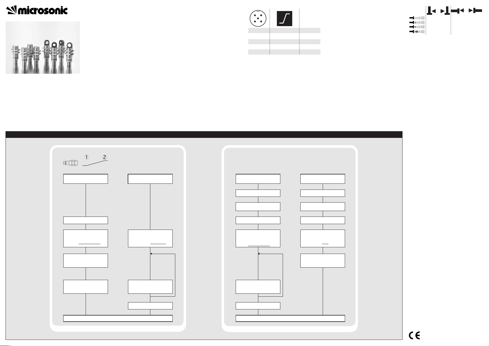
Sensor adjustment with Teach-in procedure
Set window
margins
Place object at position
Connect Com for about
3 s to +U
B
, until both LEDs
flash simultaneously
Both LEDs:
Place object at position
flash alternately
Set rising/falling output
characteristic curve
Connect Com for about
13 s to +U
B
, until both
LEDs flash alternately
Green LED:
Yellow LED:
flashes
on: rising,
off: falling
characteristic
curve
Switch
Teach-in / synchronization
Switch off power supply
Reset to factory setting
Switch off power supply
Connect Com to -U
B
Switch on power supply
Keep Com connected to
-U
B
for about 3 s, until
both LEDs flash
simultaneously
Green LED:
Yellow LED:
flashes
on: Teach-in
off: synchro-
nization
Connect Com to -U
B
Switch on power supply
Keep Com connected to
-U
B
for about 13 s, until
both LEDs stop
flashing
Disconnect Com from -U
B
before switching off
power supply
Connect Com for about
1 s to +U
B
Normal operating mode
To change output
characteristic connect
Com for about 1 s to +U
B
Wait for about 10 s
To change operation mode
connect
Com for about 1 s to -U
B
Wait for about 10 s
Normal operating mode
1
3
colour
+U
B
-U
B
brown
blue
4
2
5
-
I|U
black
white
Com grey
1
5
2
34
≥0,25 m
≥0.35 m
≥1,30 m
≥2.50 m
≥0.40 m
≥0.70 m
≥2.50 m
≥4.00 m
A
B
Ultrasonic Sensors
Set analogue output
Further settings
Operating Instructions
pico+15/I pico+15/WK/I
pico+25/I pico+25/WK/I
pico+35/I pico+35/WK/I
pico+100/I pico+100/WK/I
pico+15/U pico+15/WK/U
pico+25/U pico+25/WK/U
pico+35/U pico+35/WK/U
pico+100/U pico+100/WK/U
Ultrasonic sensor with one analogue output
Product Description
The pico+sensor offers a non-contact
measurement of the distance to an
object that has to be present within
the sensor’s detection zone. Depending on the set window limits, a distance-proportional analogue signal is
output.
The window limits of the analogue
output and its characteristic can be
adjusted with the Teach-in procedure.
Two LEDs indicate operation and the
state of the analogue output.
Safety Notes
Read the operating instructions
prior to start-up.
Connection, installation and
adjustment works should be carried out by expert personnel only.
No safety component in
accordance with the EU Machine
Directive
Proper use
pico+ultrasonic sensors are used for
non-contact detection of objects.
Installation
Mount the sensor at the installa-
tion site.
Connect a connection cable to the
M12 device plug.
Start-Up
Connect the power supply.
Carry out the sensor adjustment in
accordance with the diagram.
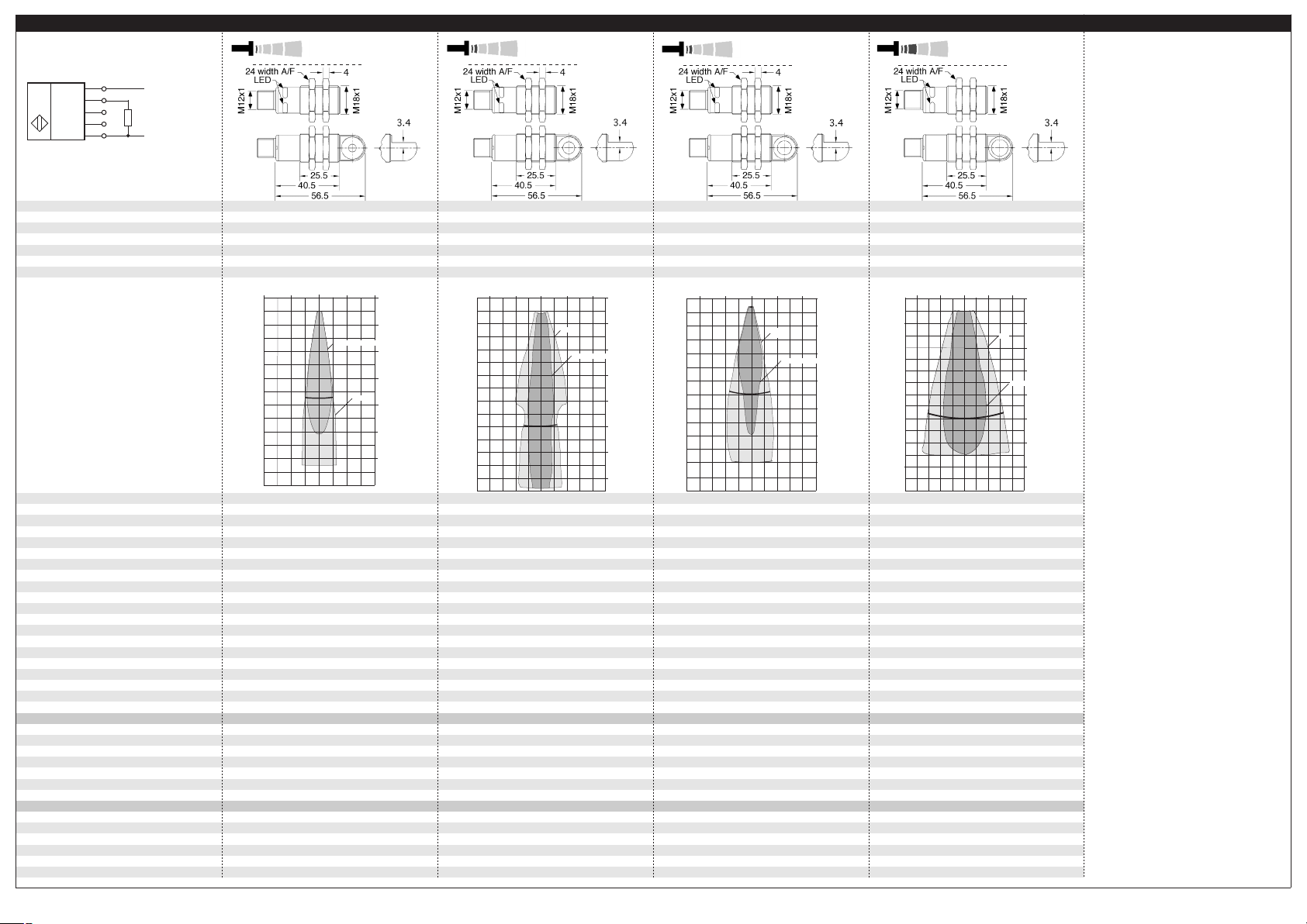
Fig. 1: Pin assignment with view onto sensor
plug and colour coding of the
microsonic connection cable
Factory Setting
Rising analogue characteristic
curve between the blind zone and
the operating range
Multifunctional input »Com« set
to »Teach-in«
Synchronization
If the assembly distance falls below
the values shown in Fig. 2, the internal synchronization should be used.
For this purpose set the switched
outputs of all sensors in accordance
to the diagram »Sensor adjustment
with Teach-in procedure« at first.
Then set the multifunctional output
»Com« to »synchronization« (see
»Further settings«). Finally connect
pin 5 of the sensors plug of all sensors.
Fig.2: Assembly distances, indicating syn-
chronization
Maintenance
microsonic sensors are maintenancefree. In case of excess caked-on dirt
we recommend to clean the white
sensor surface.
Notes
The sensors of the pico+ family
have a blind zone. Within this
zone a distance measurement is
not possible.
The pico+ sensors are equipped
with an internal temperature compensation. Due to the sensors self
heating, the temperature compensation reaches its optimum working-point after approx. 20 minutes
of operation.
In the normal operating mode, an il-
luminated yellow LED signals the object is within the adjusted window
limits.
If synchronization is activated the
Teach-in is disabled (see »Further
settings«).
The sensor can be reset to its fac-
tory setting (see »Further settings«).
Optionally all Teach-in and addi-
tional sensor parameter settings
can be made using the LinkControl adapter (optional accessory)
and the LinkControl software for
windows© .
2004/108/EC
Technical data
blind zone
operating range
maximum range
angle of beam spread
20 mm
150 mm
250 mm
See detection zone
transducer frequency
resolution
detection zones
for different objects:
The dark grey areas are determined with a
round bar and indicate the typical operating
range of a sensor. In order to obtain the light
grey areas, a plate (100 x 100 mm) is
introduced into the beam spread from the side.
In doing so, the optimum angle between
plate and sensor is always employed.
This therefore indicates the maximum
detection zone of the sensor.
It is not possible to evaluate ultrasonic
reflections outside this area.
380 kHz
reproducibility
accuracy
no-load current consumption
operating voltage ripple
± 0.15 %
± 1 % (Temperature drift internal compensated)
< 40 mA
±10 %
housing
max. tightening torque of nuts
brass sleeve, nickel-plated, plastic parts: PBT;
ultrasonic transducer: polyurethane foam,
class of protection to EN 60 529
type of connection
controls
indicators
IP 67
Teach-in via pin 5 (Com)
LED green (operation)
programmable
synchronisation
operating temperature
LED yellow (state of analogue output)
Teach-in, LinkControl
internal synchronisation up to 10 sensors
-25°C to +70°C
storage temperature
response time
1)
time delay before availability
1)
norm conformity
-40°C to +85°C
32 ms
< 300 ms
EN 60947-5-2
operating voltage U
B
RL ≤ 500 Ω, rising/falling characteristic
10 - 30 V DC for RL ≤ 100 Ω,
20 - 30 V DC for RL > 100 Ω,
terminal reverse polarity protected
order no. directly radiating
weight
order no. angular head
weight
pico+15/I
30 g
pico+15/WK/I
35 g
operating voltage U
B
order no. directly radiating
RL ≥ 100 kΩ, short circuit proof,
rising/falling characteristic
15 - 30 V DC, terminal reverse polarity protected
pico+15/U
weight
order no. angular head
weight
1) Can be programmed with LinkControl
30 g
pico+15/WK/U
35 g
65 mm
350 mm
120 mm
1,000 mm
600 mm
See detection zone
1,300 mm
See detection zone
400 kHz
200 kHz
analogue window
analogue window
± 0.15 %
± 1 % (Temperature drift internal compensated)
± 0.15 %
± 1 % (Temperature drift internal compensated)
< 40 mA
±10 %
< 40 mA
±10 %
brass sleeve, nickel-plated, plastic parts: PBT;
ultrasonic transducer: polyurethane foam,
brass sleeve, nickel-plated, plastic parts: PBT;
ultrasonic transducer: polyurethane foam,
IP 67
IP 67
Teach-in via pin 5 (Com)
LED green (operation)
Teach-in via pin 5 (Com)
LED green (operation)
LED yellow (state of analogue output)
Teach-in, LinkControl
LED yellow (state of analogue output)
Teach-in, LinkControl
internal synchronisation up to 10 sensors
-25°C to +70°C
internal synchronisation up to 10 sensors
-25°C to +70°C
-40°C to +85°C
64 ms
-40°C to +85°C
80 ms
< 300 ms
EN 60947-5-2
< 300 ms
EN 60947-5-2
RL ≤ 500 Ω, rising/falling characteristic
10 - 30 V DC for RL ≤ 100 Ω,
RL ≤ 500 Ω, rising/falling characteristic
10 - 30 V DC for RL ≤ 100 Ω,
20 - 30 V DC for RL > 100 Ω,
terminal reverse polarity protected
20 - 30 V DC for RL > 100 Ω,
terminal reverse polarity protected
pico+35/I
30 g
pico+100/I
30 g
pico+35/WK/I
35 g
pico+100/WK/I
35 g
RL ≥ 100 kΩ, short circuit proof,
rising/falling characteristic
RL ≥ 100 kΩ, short circuit proof,
rising/falling characteristic
15 - 30 V DC, terminal reverse polarity protected
pico+35/U
15 - 30 V DC, terminal reverse polarity protected
pico+100/U
30 g
pico+35/WK/U
30 g
pico+100/WK/U
35 g
35 g
+U
B
-U
B
R
L
Com
1
2
4
5
3
1 analogue output
U
U|I
pico+15...
8 cm
4 cm
0 cm
4 cm
8 cm
0 cm
4 cm
8 cm
12 cm
16 cm
20 cm
24 cm
Round bar ø 10 mm
Plate
pico+35...
pico+100...
0 cm
10 cm
20 cm
30 cm
40 cm
50 cm
60 cm
Plate
Round bar ø 27 mm
20 cm
10 cm
0 cm
10 cm
20 cm
35 cm
0 m
0,2m
0,8 m
1,0 m
1,3 m
0,4 m
0 m
0,4 m
0,6 m
0,4 m
1,0 m
1,4 m
0,2 m
0,2 m
Round bar ø 27 mm
Plate
microsonic GmbH | Hauert 16 | 44227 Dortmund | Germany | Tel: +49 2 31 / 97 51 51-0 | Fax: +49 2 31 / 97 51 51-51 | E-Mail: info@microsonic.de | www.microsonic.de |
The content of this document is subject to technical changes. Specifications in this document are presented in a descriptive way only. They do not warrant any product features.
MV-DO-119336-372402
pico+25...
30 mm
250 mm
350 mm
See detection zone
0.069 mm
epoxy resin with glass content
15 Nm
5-pin M12 initiator plug
analogue output 4-20 mA
analogue output 0-10 V
320 kHz
0.069 mm bis 0.10 mm, depending on the
analogue window
10 cm
5 cm
± 0.15 %
± 1 % (Temperature drift internal compensated)
< 40 mA
±10 %
brass sleeve, nickel-plated, plastic parts: PBT;
ultrasonic transducer: polyurethane foam,
epoxy resin with glass content
15 Nm
IP 67
5-pin M12 initiator plug
Teach-in via pin 5 (Com)
LED green (operation)
LED yellow (state of analogue output)
Teach-in, LinkControl
internal synchronisation up to 10 sensors
-25°C to +70°C
-40°C to +85°C
32 ms
< 300 ms
EN 60947-5-2
RL ≤ 500 Ω, rising/falling characteristic
10 - 30 V DC for R
20 - 30 V DC for RL > 100 Ω,
terminal reverse polarity protected
pico+25/I
30 g
pico+25/WK/I
35 g
RL ≥ 100 kΩ, short circuit proof,
rising/falling characteristic
15 - 30 V DC, terminal reverse polarity protected
pico+25/U
30 g
pico+25/WK/U
35 g
≤ 100 Ω,
L
0.069 mm bis 0.17 mm, depending on the
0 cm
Plate
Round bar ø 10 mm
0 cm
5 cm
10 cm
15 cm
20 cm
25 cm
30 cm
35 cm
epoxy resin with glass content
15 Nm
10 cm
5 cm
5-pin M12 initiator plug
0.069 mm bis 0.38 mm, depending on the
epoxy resin with glass content
15 Nm
5-pin M12 initiator plug
 Loading...