

Page 1
Operating Instructions
Ultrasonic proximity switch with
one switched output
pico+15/F pico+15/WK/F
pico+25/F pico+25/WK/F
pico+35/F pico+35/WK/F
pico+100/F pico+100/WK/F
Product description
The pico+sensor offers a non-contact
measurement of the distance to an
object which must be positioned
within the sensor’s detection zone.
The switched output is set conditional upon the adjusted detect distance.
Via the Teach-in procedure, the detect distance and operating mode
can be adjusted. Two LEDs indicate
operation and the state of the switched output.
The pico+sensors are IO-Link-capable
in accordance with IO-Link specification V1.0.
Safety instructions
Read the operating instructions
prior to start-up.
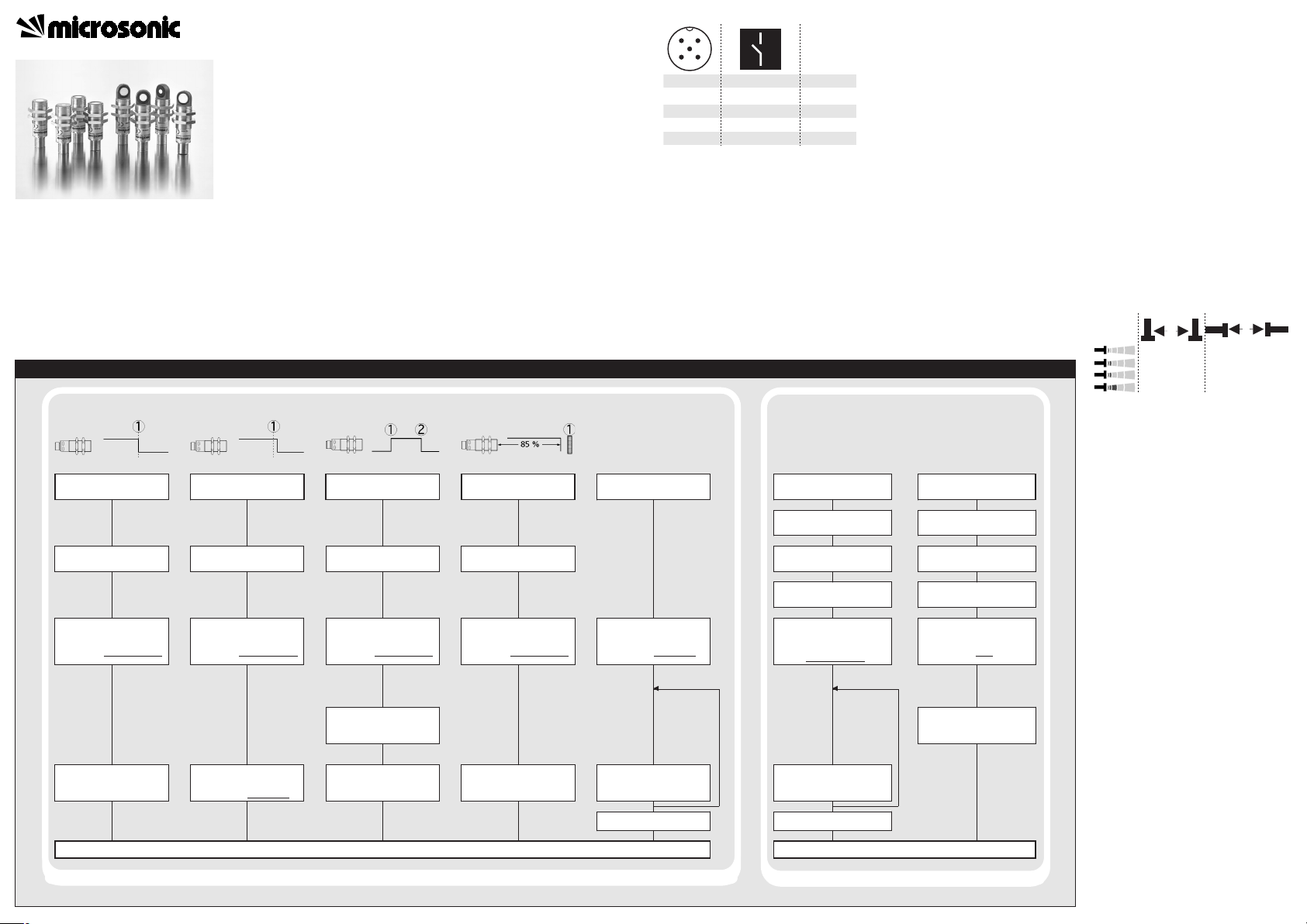
Sensor adjustment with Teach-in procedure
Set detect point
– method A
Place object at position
Connect Com for about
3 s to +U
B
, until both
LEDs flash simultaneously
Both LEDs:
flash alternately
Set detect point +8 %
– method B
Place object at position
Connect Com for about
3 s to +U
B
, until both
LEDs flash simultaneously
Both LEDs:
flash alternately
Set window mode
Set two way reflective
barrier
Set NOC/NCC
Place object at position
Install reflector at
position
Connect Com for about
3 s to +U
B
, until both
LEDs flash simultaneously
Both LEDs:
flash alternately
Connect Com for about
3 s to +U
B
, until both
LEDs flash simultaneously
Both LEDs:
flash alternately
Connect Com for about
13 s to +U
B
, until both
LEDs flash alternately
Green LED:
Yellow LED:
flashes
on: NOC
off: NCC
Switch-over
Teach-in / synchronisation
Switch off operating
voltage
Reset to factory setting
Switch off operating
voltage
Connect Com to -U
B
Switch on
operating voltage
Keep Com connected to
-U
B
for about 3 s, until
both LEDs flash
simultaneously
Green LED:
Yellow LED:
flash
on: Teach-in
off: Synchronisation
Connect Com to -U
B
Switch on
operating voltage
Keep Com connected to
-U
B
for about 13 s, until
both LEDs stop
flashing
Connect Com for about
1 s to +U
B
Normal operating mode
Connect Com for about
3 s to +U
B
, until both
LEDs flash alternately
Place object at position
Both LEDs:
flash mutually
Connect Com for about
1 s to +U
B
Connect Com for about
10 s to +U
B
To change output
characteristic connect
Com for about 1 s to +U
B
Wait for 10 s
To change operation
mode connect
Com for about 1 s to -U
B
Wait for 10 s
Normal operating mode
Disconnect Com from -U
B
before switching off
supply voltage
Connection, installation and ad-
justments may only be carried out
by qualified staff.
No safety component in
accordance with the EU Machine
Directive
Use for intended purpose only
pico+ultrasonic sensors are used for
non-contact detection of objects.
Installation
Mount the sensor at the place of
fitting.
Connect a connection cable to the
M12 device plug.
Fig. 1: Pin assignment with view onto sensor
plug and colour coding of the
microsonic connection cables
Start-up
Connect the power supply.
Carry out sensor adjustment in
accordance with the diagram.
1
3
colour
+U
B
-U
B
brown
blue
4
2
5
F
-
black
white
Com grey
1
5
2
34
Factory setting
Detect point operation
Switched output on NOC
Detect distance at operating range
Multi-function input »Com« set to
»Teach-in«
Filter at F01
Filter strength at P01
Operating modes
Three operating modes are available
for the switched output:
Operation with one detect point
The switched output is set when the
object falls below the set detect
point.
Window mode
The switched output is set when the
object is within the set window.
Two-way reflective barrier
The switched output is set when the
object is between sensor and fixed
reflector.
Synchronisation
If under multiple sensor operation
the assembly distance falls below the
values shown in Fig. 2, the internal
synchronisation should be used. For
this purpose set the switched outputs of all sensors in accordance with
the diagram »Sensor adjustment
with the Teach-in procedure«. Then
change the multi-function output
»Com« to »synchronisation« (see
»Further settings«). Finally interconnect each pin 5 of the sensors to be
synchronised.
Fig. 2: Assembly distances
Maintenance
microsonic sensors are maintenancefree. In case of excess caked-on dirt
we recommend cleaning the white
sensor surface
Notes
The sensors of the pico+ family
have a blind zone, within which a
distance measurement is not possible.
The pico+ sensors are equipped
with an internal temperature compensation. Due to the sensors self
heating, the temperature compensation reaches its optimum working-point after approx. 20 minutes
of operation.
In the normal operating mode, an il-
luminated yellow LED signals that the
switched output is switched
through.
The pico+sensors have a push-pull
switched output.
In the »Two-way reflective barrier«
operating mode, the object has to
be within the range of 0-85 % of
the set distance.
≥0,25 m ≥1,30 m
≥0,35 m
≥0,40 m
≥2,50 m
≥2,50 m
≥0,70 m
≥4,00 m
A
B
Ultrasonic Sensors
Set switched output
Further Settings
Page 2
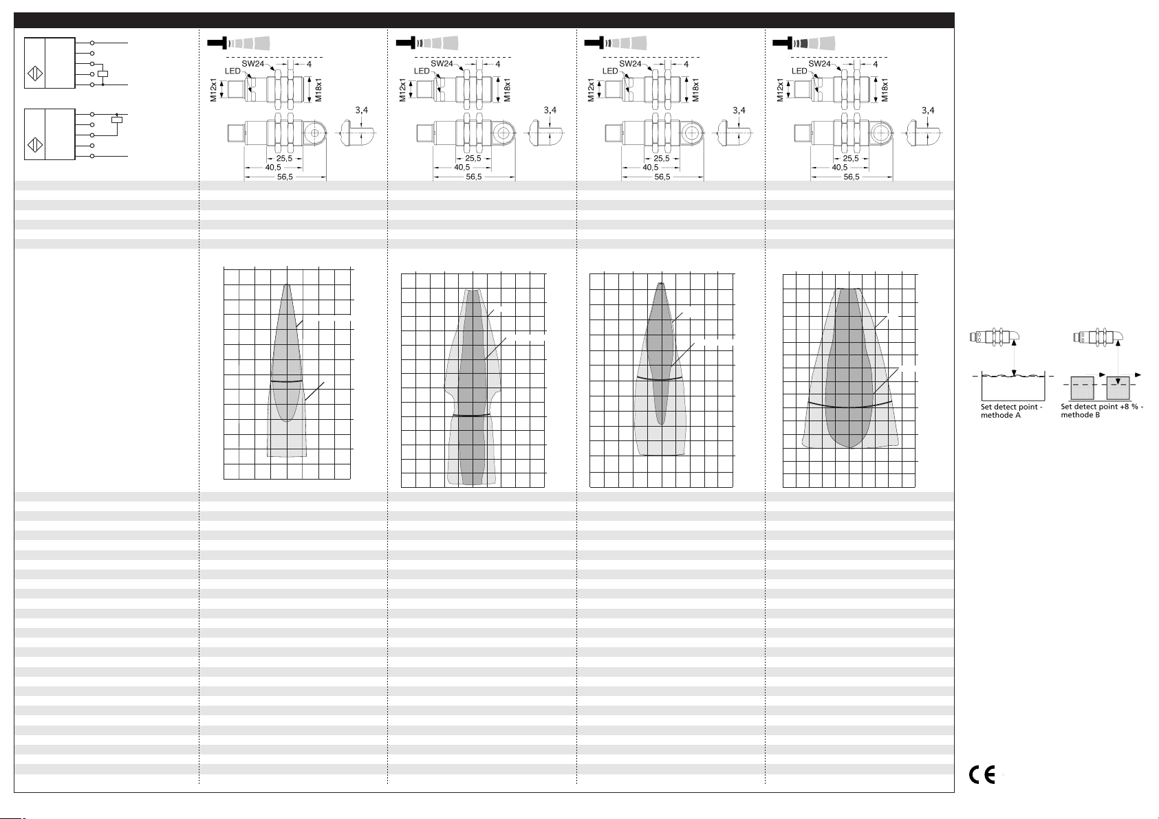
Technical data
blind zone
operating range
maximum range
angle of beam spread
20 mm
150 mm
30 mm
250 mm
250 mm
see detection zone
350 mm
see detection zone
transducer frequency
resolution
reproducibility
380 kHz
0.069 mm
320 kHz
0.069 mm
± 0.15 %
± 0.15 %
accuracy
operating voltage U
B
voltage ripple
no-load current consumption
±1 % (temperature drift internally compensated)
10 - 30 V DC, reverse polarity protection
±1 % (temperature drift internally compensated)
10 - 30 V DC, reverse polarity protection
±10 %
< 40 mA
±10 %
< 40 mA
housing
max. tightening torque of nuts
brass sleeve, nickel-plated, plastic parts: PBT;
ultrasonic transducer: polyurethane foam,
brass sleeve, nickel-plated, plastic parts: PBT;
ultrasonic transducer: polyurethane foam,
class of protection per EN 60 529
type of connection
controls
indicators
IP 67
IP 67
Teach-in via pin 5 (Com)
LED green (operation)
Teach-in via pin 5 (Com)
LED green (operation)
programmable
synchronisation
operating temperature
LED yellow (state of output)
Teach-in, LinkControl
LED yellow (state of output)
Teach-in, LinkControl
internal synchronisation up to 10 sensors
-25°C to +70°C
internal synchronisation up to 10 sensors
-25°C to +70°C
storage temperature
switched output
switching hysteresis
1)
-40°C to +85°C
Push-Pull, I
max
= 100 mA
-40°C to +85°C
Push-Pull, I
max
= 100 mA
switchable NOC/NCC, short-circuit-proof
2 mm
switchable NOC/NCC, short-circuit-proof
3 mm
switching frequency
1)
response time
1)
time delay before availability
1)
norm conformity
25 Hz
32 ms
25 Hz
32 ms
< 300 ms
EN 60947-5-2
< 300 ms
EN 60947-5-2
order no. directly radiating
weight
pico+15/F
pico+25/F
30 g
30 g
order no. angular head
weight
1) Can be programmed with LinkControl
pico+15/WK/F
35 g
pico+25/WK/F
35 g
65 mm
350 mm
120 mm
1,000 mm
600 mm
see detection zone
1,300 mm
see detection zone
400 kHz
0.069 mm
200 kHz
0.069 mm
± 0.15 %
± 0.15 %
±1 % (temperature drift internally compensated)
10 - 30 V DC, reverse polarity protection
±1 % (temperature drift internally compensated))
10 - 30 V DC, reverse polarity protection
±10 %
< 40 mA
±10 %
< 40 mA
brass sleeve, nickel-plated, plastic parts: PBT;
ultrasonic transducer: polyurethane foam,
brass sleeve, nickel-plated, plastic parts: PBT;
ultrasonic transducer: polyurethane foam,
IP 67
IP 67
Teach-in via pin 5 (Com)
LED green (operation)
Teach-in via pin 5 (Com)
LED green (operation)
LED yellow (state of output)
Teach-in, LinkControl
LED yellow (state of output)
Teach-in, LinkControl
internal synchronisation up to 10 sensors
-25°C to +70°C
internal synchronisation up to 10 sensors
-25°C to +70°C
-40°C to +85°C
Push-Pull, I
max
= 100 mA
-40°C to +85°C
Push-Pull, I
max
= 100 mA
switchable NOC/NCC, short-circuit-proof
5 mm
switchable NOC/NCC, short-circuit-proof
20 mm
12 Hz
64 ms
10 Hz
80 ms
< 300 ms
EN 60947-5-2
< 300 ms
EN 60947-5-2
pico+35/F
pico+100/F
30 g
30 g
pico+35/WK/F
35 g
pico+100/WK/F
35 g
+U
B
-U
B
F
Com
1
2
4
5
3
Push-Pull output in pnp circuit
U
+U
B
-U
B
F
Com
1
2
4
5
3
Push-Pull output in npn circuit
U
pico+15...
pico+25...
pico+35...
pico+100...
2004/108/EC
detection zones
The dark grey areas represent the zone
where it is easy to recognise the normal
reflector (round bar). This indicates the typical
operating range of the sensors. The light
grey areas represent the zone where a
very large reflector – for instance a
plate – can still be regognized. The
requirement here is for an optimum
alignment to the sensor. It is not
for different objects:
possible to evaluate ultrasonic
reflections outside this area.
■ In the »Set detect point – method
A« Teach-in procedure the actual
distance to the object is taught to
the sensor as the detect point. If
the object moves towards the
sensor (e.g. with level control) then
the taught distance is the level at
which the sensor has to switch the
output.
If the object to be scanned moves
into the detection area from the
side, the »Set detect point +8 % –
method B« Teach-in procedure
should be used. In this way the
switching distance is set 8 % further than the actual measured distance to the object. This ensures a
4 cm
0 cm
0 cm
0 cm
0 cm
4 cm
4 cm
4 cm
Rohr ø 10 mm
Rohr ø 10 mm
Rohr ø 10 mm
Round bar ø 10 mm
ausgerichtete Platte
ausgerichtete Platte
Plate
8 cm
8 cm
8 cm
8 cm
0 cm
0 cm
0 cm
4 cm
4 cm
4 cm
8 cm
8 cm
8 cm
12 cm
12 cm
12 cm
16 cm
16 cm
16 cm
20 cm
20 cm
20 cm
24 cm
24 cm
24 cm
10 cm
5 cm
0 cm
5 cm
Plate
Round bar ø 10 mm
10 cm
0 cm
5 cm
10 cm
15 cm
20 cm
25 cm
30 cm
35 cm
20 cm
10 cm
0 cm
10 cm
Plate
Round bar ø 27 mm
20 cm
0 cm
10 cm
20 cm
30 cm
35 cm
40 cm
50 cm
60 cm
0,4 m
0,2 m
0 m
0 m
0,2m
Plate
0,4 m
0,6 m
Round bar ø 27 mm
0,8 m
1,0 m
1,0 m
1,3 m
1,4 m
0,4 m
0,2 m
reliable switching distance even if
the height of the objects varies
slightly.
Fig. 4: Setting the detect point for different
directions of movement of the object
4 cm
4 cm
8 cm
8 cm
4 cm
4 cm
8 cm
8 cm
epoxy resin with glass content
15 Nm
5-pin M12 circular plug
epoxy resin with glass content
15 Nm
5-pin M12 circular plug
epoxy resin with glass content
15 Nm
5-pin M12 circular plug
epoxy resin with glass content
15 Nm
5-pin M12 circular plug
If synchronization is activated the
Teach-in is disabled (see »Further
settings«).
The sensor can be reset to its fac-
tory setting (see »Further settings«).
Using the LinkControl adapter (op-
tional accessory) and the LinkControl software for Windows, all
Teach-in and additional sensor parameter settings can be optionally
undertaken.
Page 3
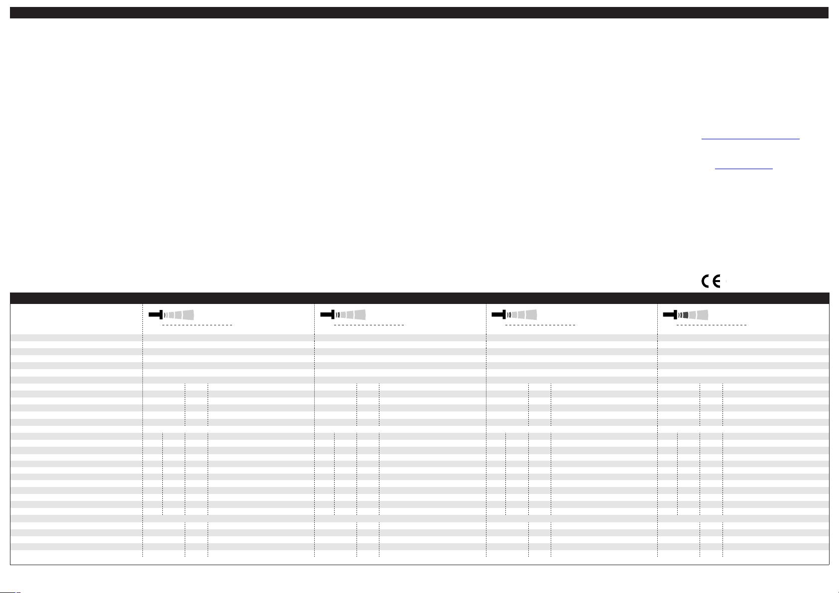
IO-Link mode
The pico+ sensors are IO-Link-capable in accordance with IO-Link specification V1.0.
Pointer
In IO-Link mode Teach-in, Link-
Control and synchronization via
pin 5 are not available.
In IO-Link mode pin 5 must not be
connected to any potential.
For current information about IO-
Link please contact the microsonic
sales department.
Synchronisation in IO-Link mode
In IO-Link mode each sensor is synchronized on the protocol of the IOLink master.
In multiple sensor operation the sensors are synchronous if the master
protocols are synchronous.
Process data
The pico+ cyclically transmits the
measured distance value with a resolution of 0,1 mm and the state of
the switched output.
Service data
The following sensor parameters
may be set via IO-Link interface using
the IO-Link device description (IODD).
Detect point 1
The switched output is activated
when the distance to an object is under that of the present detect point.
Return detect point 1
The switched output is reactivated
when the distance to an object is
greater than the present return detect point (detect point + hysteresis).
Pointer
The return detect point 1 must al-
ways be greater than the detect
point 1.
Detect point 2, return detect point 2
By programming these two detect
distances the window mode is activated.
Pointer
The return detect point 2 must al-
ways be smaller than the detect
point 2.
NOC/NCC operation
The NCC or NOC output function can
be present for the switched output.
Measurement filter
pico+ ultrasonic sensors provide for a
choice of 3 filter settings:
F00
No filter, each ultrasonic measurement acts in an unfiltered manner
on the output.
F01
Standard filter, on the object continuously approaching the sensor,
the ongoing interval is immediately taken on and the output
correspondingly activated. The effect of the object abruptly moving
away from the sensor is for the
existing distance to be saved for a
retaining time dependent on the
filter strength and for the switched
output state to be maintained.
F02
Average value filter, forms the
arithmetic mean across a number
of measurements. The output is
activated in keeping with the average value. The number of measurements, from which the average
value is formed, depends on the
selected filter strength.
Filter strength
A filter strength between 0 – weak
filter effect – and 9 – pronounced filter effect – can be selected for each
measurement filter.
Foreground suppression
Spurious reflections, caused by objects in the foreground of the sensor
may be blocked out by the foreground suppression.
Pointer
Check that the object in the fore-
ground does not cause multiple
reflections.
The object in the foreground must
not cover the sensor in a way that
the detection zone is influenced.
System commands
With 4 system commands the following settings may be carried out:
Teach-in detect point – method A.
Teach-in detect point – method B.
Teach-in two way reflective barrier.
Reset sensor to factory settings.
Pointer
To achieve the maximum resolution
the Master Cycle Time has to comply
with the following requirements:
Min Cycle Time ≤ Master Cycle
Time ≤ Min Cycle Time + 1.2 ms.
If this condition can not be full-
filled, sporadic discontinuities of
the measurement value can occur.
In this case the Master Cycle Time
has to be increased in 400 µs steps
until the discontinuities of the
measurement disappear.
Pointer
If the pico+ sensor was set using
Teach-in or LinkControl it is recommended to reset the sensor
to the factory setting prior to
using it in IO-Link mode (s.
»Further settings«).
IODD file
The latest IODD file you will find
on
the internet under
www.microsonic.de/en/IODD.
For further informations on IO-Link
see www.io-link.com.
index
index
format
UINT16
UINT16
UINT16
UINT16
index
format
UINT16
UINT16
UINT16
UINT16
format
UINT16
466-65,512 (32 - 350 mm) 1)
> 5,094: window mode deactivated
451-65,512 (31 - 349 mm) 1)
UINT16
UINT16
UINT16
format
UINT16
975-65,512 (67 - 600 mm) 1)
> 8,733: window mode deactivated
961-65,512 (66 - 599 mm) 1)
UINT16
UINT16
UINT16
> 5,094: window mode deactivated
> 8,733: window mode deactivated
1,776-65,512 (122 - 1,300 mm) 1)
> 18,922: window mode deactivated
1,761-65,512 (121 - 1,299 mm) 1)
> 18,922: window mode deactivated
pico+15...
pico+35...
pico+100...
IO-Link mode
MV-DO-108322-372394
microsonic GmbH | Hauert 16 | 44227 Dortmund | Germany | telefone +49 2 31 / 97 51 51-0 | telefax +49 2 31 / 97 51 51-51 | e-mail: info@microsonic.de | www.microsonic.eu
The content of this document is subject to technical changes. Specifications in this document are presented in a descriptive way only. They do not confirm any product features.
IO-Link data
physical layer
SIO mode support
min cycle time
format of process data
content of process data
service data IO-Link specific
service data sensor specific
return detect point 1
return detect point 2
foreground suppression
Teach-in via Pin 5 in SIO mode
Teach-in detect point – method A
Teach-in detect point – method B
Teach-in two way reflective barrier
reset to factory settings
baud rate
Vendor name
Vendor text
Product name
Product ID
Product text
detect point 1
detect point 2
switching mode
filter strength
system commands
yes
8 ms
COM 2 (38.400 Bd)
16 Bit, R, UNI16
Bit 0: state of switched output;
Bit 1-15: distance value with 0,1 mm resolution
0x10
0x11
0x12
0X13
0x14
0x40
0x41
0x47
0x48
0x42 UINT8
0x43
filter
0x44
0x49
0x4A
0x02
0x02
0x02
0x02
1)
Distance values, e.g. detect points, are given as multiple of the internal resolution of the measurement value = 0,069 mm (example: 320 ≙ 22 mm). The values in the table are decimal.
access value
RRmicrosonic GmbH
RRpico+
R Ultraschall-Sensor
access
R/W
R/W
R/W
R/W
R/W
UINT8
R/W
UINT8
R/W
UINT8
R/W
R/W
UINT8
access value
WW161
WW164
www.microsonic.de
15/F;15/WK/F
range (dez)
306-3,609 (21-248 mm) 1)
320-3,624 (22-249 mm) 1)
335-65,512 (23 - 250 mm) 1)
> 3,638: window mode deactivated
320-65,512 (22 - 250 mm) 1)
> 3.638: window mode deactivated
00: NCC, 02: NOC
00-02: F00 - F02
00-09: P00 - P09
0-1,878 (0-129 mm) 1)
00: deactivated, 16: activated
162
168
yes
8 ms
COM 2 (38.400 Bd)
16 Bit, R, UNI16
Bit 0: state of switched output;
Bit 1-15: distance value with 0,1 mm resolution
index
0x10
0x11
0x12
0X13
0x14
index
0x40
0x41
0x47
0x48
0x42 UINT8
0x43
0x44
0x49
0x4A
index
0x02
0x02
0x02
0x02
access value
RRmicrosonic GmbH
RRpico+
R Ultraschall-Sensor
access
R/W
R/W
R/W
R/W
R/W
UINT8
R/W
UINT8
R/W
UINT8
R/W
R/W
UINT8
access value
WW161
WW164
pico+25...
www.microsonic.de
25/F;25/WK/F
range (dez)
436-5,065 (30 - 348 mm) 1)
451-5,080 (31 - 349 mm) 1)
00: NCC, 02: NOC
00-02: F00 - F02
00-09: P00 - P09
0-3,246 (0-223 mm) 1)
00: deactivated, 16: activated
162
168
yes
16 ms
COM 2 (38.400 Bd)
16 Bit, R, UNI16
Bit 0: state of switched output;
Bit 1-15: distance value with 0,1 mm resolution
index
0x10
0x11
0x12
0X13
0x14
index
0x40
0x41
0x47
0x48
0x42 UINT8
0x43
0x44
0x49
0x4A
index
0x02
0x02
0x02
0x02
access value
RRmicrosonic GmbH
RRpico+
R Ultraschall-Sensor
access
R/W
R/W
R/W
R/W
R/W
UINT8
R/W
UINT8
R/W
UINT8
R/W
R/W
UINT8
access value
WW161
WW164
www.microsonic.de
35/F;35/WK/F
range (dez)
946-8,704 (65 - 598 mm) 1)
961-8,718 (66 - 599 mm) 1)
00: NCC, 02: NOC
00-02: F00 - F02
00-09: P00 - P09
0-4,236 (0-291 mm) 1)
00: deactivated, 16: activated
162
168
yes
20 ms
COM 2 (38.400 Bd)
16 Bit, R, UNI16
Bit 0: state of switched output;
Bit 1-15: distance value with 0,1 mm resolution
index
0x10
0x11
0x12
0X13
0x14
index
0x40
0x41
0x47
0x48
0x42 UINT8
0x43
0x44
0x49
0x4A
index
0x02
0x02
0x02
0x02
access value
RRmicrosonic GmbH
RRpico+
R Ultraschall-Sensor
access
R/W
R/W
R/W
R/W
R/W
UINT8
R/W
UINT8
R/W
UINT8
R/W
R/W
UINT8
access value
WW161
WW164
www.microsonic.de
100/F;100/WK/F
range (dez)
1,747-18,892 (120 - 1,298 mm) 1)
1,761-18,907 (121 - 1,299 mm) 1)
00: NCC, 02: NOC
00-02: F00 - F02
00-09: P00 - P09
0-12,969 (0-891 mm) 1)
00: deactivated, 16: activated
162
168
 Loading...