

Page 1
Product description
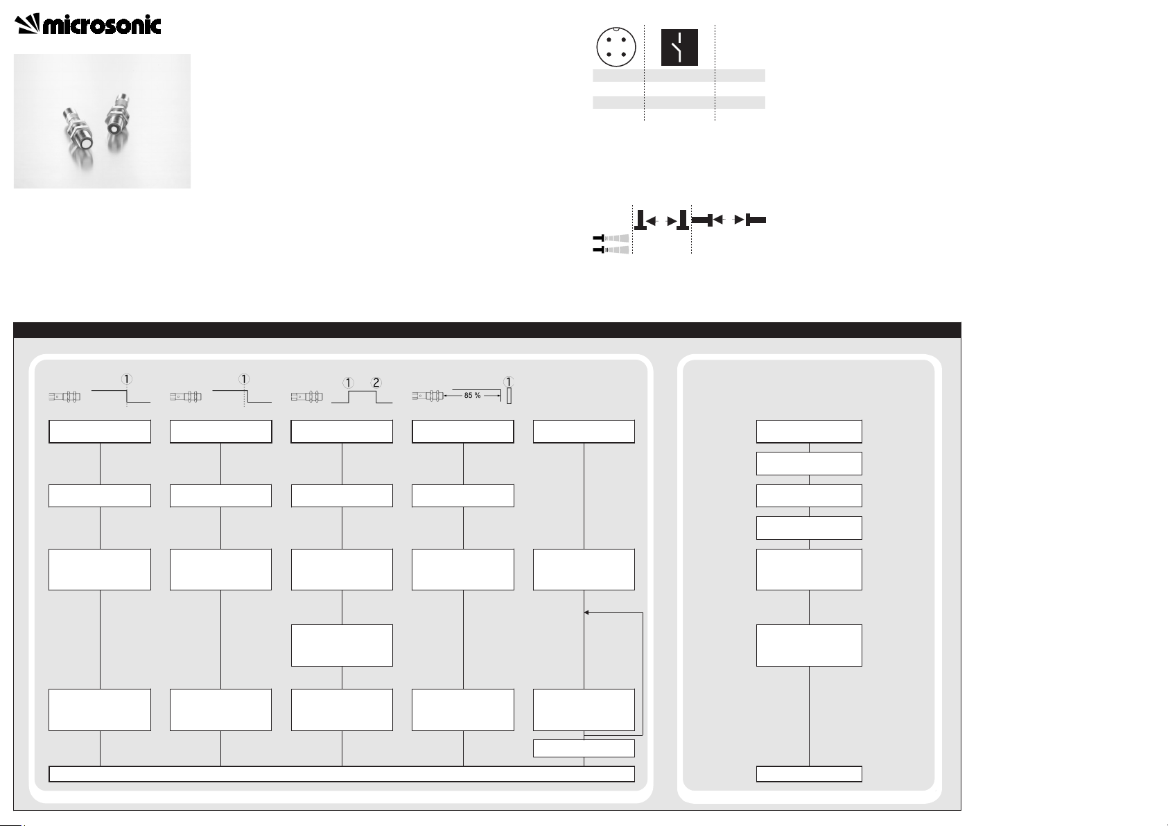
Sensor adjustment with Teach-in procedure
Set detect point -
method A
Place object at
position .
Connect Teach-in for
about 3 s to +U
B
, until
LED flashes yellow.
LED:
flashes
green/yellow
Set detect point+8 % -
method B
Place object at
position .
Connect Teach-in for
about 3 s to +U
B
, until
LED flashes yellow.
LED:
flashes
green/yellow
Set window mode
Set two way reflective
barrier
Set NOC/NCC
Place object at
position .
Install reflector at
position .
Connect Teach-in for
about 3 s to +U
B
, until
LED flashes yellow.
LED:
flashes
green/yellow
Connect Teach-in for
about 3 s to +U
B
, until
LED flashes yellow.
LED:
flashes
green/yellow
Connect Teach-in for
about 13 s to +U
B
, until
LED flashes green/yellow
alternately.
LED flashes:
green, green/
yellow:
NOC
green:
NCC
Reset to factory setting
Switch off operating
voltage.
Connect Teach-in to +U
B.
Switch on
operating voltage.
Keep Teach-in connected
to +U
B
for about 13 s,
until LED flashes
green/yellow alternately.
Connect Teach-in for
about 1 s to +U
B.
Normal operating mode
Connect Teach-in for
about 3 s to +U
B
, until
LED flashes green/yellow.
Place object at
position .
LED:
flashes
green/yellow
Connect Teach-in for
about 1 s to +U
B.
Connect Teach-in for
about 10 s to +U
B
until
both LEDs stop flashing.
To change output
characteristic connect
Teach-in for about
1 s to +U
B
.
Wait for 10 s.
Disconnect Teach-in from
+U
B
within 5 s before
switching off
supply voltage.
Normal operating mode
1
3
colour
+U
B
-U
B
brown
blue
4
2
D/E
Teach-in
black
white
12
34
≥0.25 m ≥1.3 m
≥0.25 m
≥1.4 m
A
B
Set switched output
Further Settings
Ultrasonic Sensors
The nano sensor offers a non-contact
measurement of the distance to an
object which must be positioned
within the sensor’s detection zone.
The switched output is set conditional upon the adjusted detect distance.
Via the Teach-in procedure, the detect distance and operating mode
can be adjusted. One 2-colour LED
indicates operation and the state of
the switched output.
Operating Instructions
Safety notes
Ultrasonic proximity switch with
Read the operating instructions
one switched output
nano-15/CD nano-15/CE
nano-24/CD nano-24/CE
Connection, installation and
No safety Component in accor-
prior to start-up.
adjustment works should be carried out by expert personnel only.
dance with the EU Machine Directive.
Use for intended purpose only
nano ultrasonic sensors are used for
non-contact detection of objects.
Installation
Mount the sensor at the installa-
tion site.
Connect a connection cable to the
M12 device plug.
The assembly distances shown in fig.
2 for two or more sensors should not
be fallen below in order to avoid mutual interference.
Start-up
Connect the power supply.
Carry out sensor adjustment in
accordance with the diagram.
Fig. 1: Pin assignment with view onto sensor
plug and colour coding of the
microsonic connection cables
Fig.2: Assembly distances
Factory setting
Detect point operation.
Switched output on NOC.
Detect distance at operating
range.
Operating modes
Three operating modes are available
for the switched output:
Operation with one detect point
The switched output is set when the
object falls below the set detect
point.
Window mode
The switched output is set when the
object is within the set window.
Two-way reflective barrier
The switched output is set when the
object is between sensor and fixed
reflector.
Maintenance
microsonic sensors are maintenancefree. In case of excess caked-on dirt
we recommend cleaning the white
sensor surface.
Notes
Every time the power supply is
switched on, the sensor detects its
actual operating temperature and
transmits it to the internal temperature compensation. This results
in a slight correction of the analogue output value after 45 seconds.
If the sensor was switched off for
at least 30 minutes and after power on the switched output is not
set for 30 minutes a new adjustment of the internal temperature
compensation to the actual mounting conditions takes place.
The sensors of the nano family
have a blind zone. Within this
zone a distance measurement is
not possible.
In the normal operating mode, an il-
luminated yellow LED signals that the
switched output is switched
through.
In the »Two-way reflective barrier«
operating mode, the object has to
be within the range of 0-85 % of
the set distance.
In the »Set detect point - method
A« Teach-in procedure the actual
distance to the object is taught to
the sensor as the detect point. If
the object moves towards the
sensor (e.g. with level control) then
the taught distance is the level at
which the sensor has to switch the
output.
If the object to be scanned moves
into the detection area from the
side, the »Set detect point+8 % method B« Teach-in procedure
should be used. In this way the
switching distance is set 8 % further than the actual measured distance to the object. This ensures a
reliable switching distance even if
the height of the objects varies
slightly.
Page 2
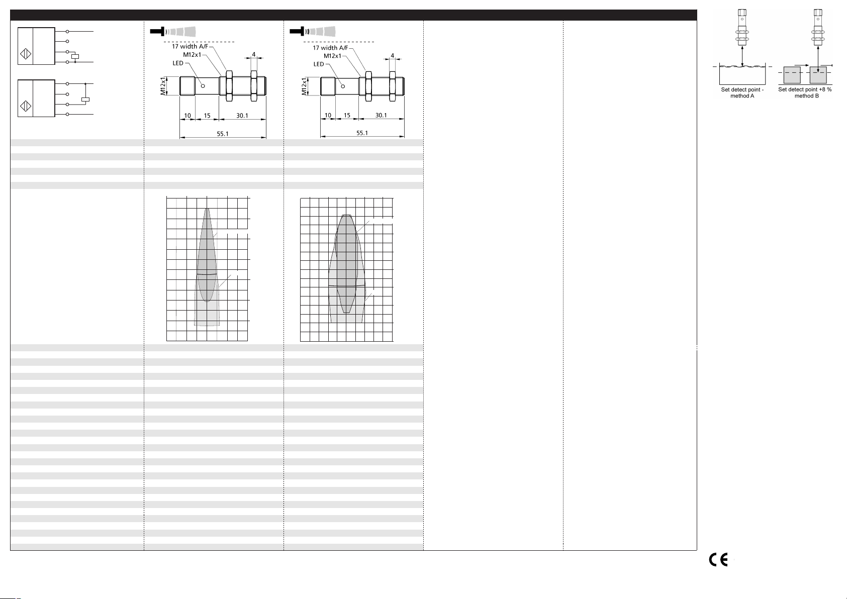
Technical data
blind zone
operating range
maximum range
angle of beam spread
20 mm
150 mm
40 mm
240 mm
250 mm
See detection zone
350 mm
See detection zone
transducer frequency
resolution, sampling rate
reproducibility
detection zones
for different objects:
The dark grey areas represent the zone
where it is easy to recognise the normal
reflector (round bar). This indicates the typical
operating range of the sensors. The light
grey areas represent the zone where a
very large reflector - for instance a
plate - can still be regognized. The
requirement here is for an optimum
alignment to the sensor. It is not
possible to evaluate ultrasonic
reflections outside this area.
380 kHz
69 µm
500 kHz
69 µm
± 0.15 %
± 0.15 %
accuracy
operating voltage U
B
voltage ripple
no-load current consumption
± 1 % (temperature drift internally compensated)
10 - 30 V DC, reverse polarity protection
± 1 % (temperature drift internally compensated)
10 - 30 V DC, reverse polarity protection
±10 %
< 25 mA
±10 %
< 35 mA
housing
max. tightening torque of nuts
brass sleeve, nickel-plated, plastic parts: PBT;
ultrasonic transducer: polyurethane foam,
brass sleeve, nickel-plated, plastic parts: PBT;
ultrasonic transducer: polyurethane foam,
epoxy resin with glass content
1 Nm
epoxy resin with glass content
1 Nm
class of protection per EN 60 529
norm conformity
type of connection
controls
IP 67
EN 60947-5-2
IP 67
EN 60947-5-2
4-pin M12 circular plug
Teach-in via pin 2
4-pin M12 circular plug
Teach-in via pin 2
indicators
programmable
operating temperature
storage temperature
LED yellow/green
Teach-in
LED yellow/green
Teach-in
-25°C to +70°C
-40°C to +85°C
-25°C to +70°C
-40°C to +85°C
weight
switching hysteresis
switching frequency
response time
15 g
2 mm
15 g
3 mm
25 Hz
24 ms
20 Hz
30 ms
time delay before availability
order no.
switched output
< 300 ms
< 300 ms
nano-15/CD
pnp, UB-2V, Imax = 200 mA
nano-24/CD
pnp, UB-2V, Imax = 200 mA
order no.
switched output
switchable NOC/NCC, short-circuit-proof
switchable NOC/NCC, short-circuit-proof
nano-15/CE
npn, -UB+2V, Imax = 200 mA
nano-24/CE
npn, -UB+2V, Imax = 200 mA
switchable NOC/NCC, short-circuit-proof
switchable NOC/NCC, short-circuit-proof
+U
B
-U
B
D
1
2
4
3
1 pnp switched output
U
+U
B
-U
B
E
1
2
4
3
1 npn switched output
U
Teach-in
Teach-in
nano-15...
nano-24...
8 cm 4 cm 0 cm 4 cm 8 cm
0 cm
4 cm
8 cm
12 cm
16 cm
20 cm
24 cm
Round bar ø 10 mm
Plate
10 cm 5 cm 0 cm 5 cm 10 cm
0 cm
5 cm
10 cm
15 cm
20 cm
25 cm
30 cm
35 cm
Plate
Round bar ø 10 mm
microsonic GmbH | Hauert 16 | Germany | 44227 Dortmund | Tel: +49 2 31 / 97 51 51-0 | Fax: +49 2 31 / 97 51 51-51 | E-Mail: info@microsonic.de | www.microsonic.de
The content of this document is subject to technical changes. Specifications in this document are presented in a descriptive way only. They do not confirm any product features.
Fig. 4: Setting the detect point for different
directions of movement of the object
The sensor can be reset to its factory setting (see »Further settings«).
*B10706*
MV-DO-131212-458857
2004/108/EC
 Loading...