

Page 1
T1 + T2
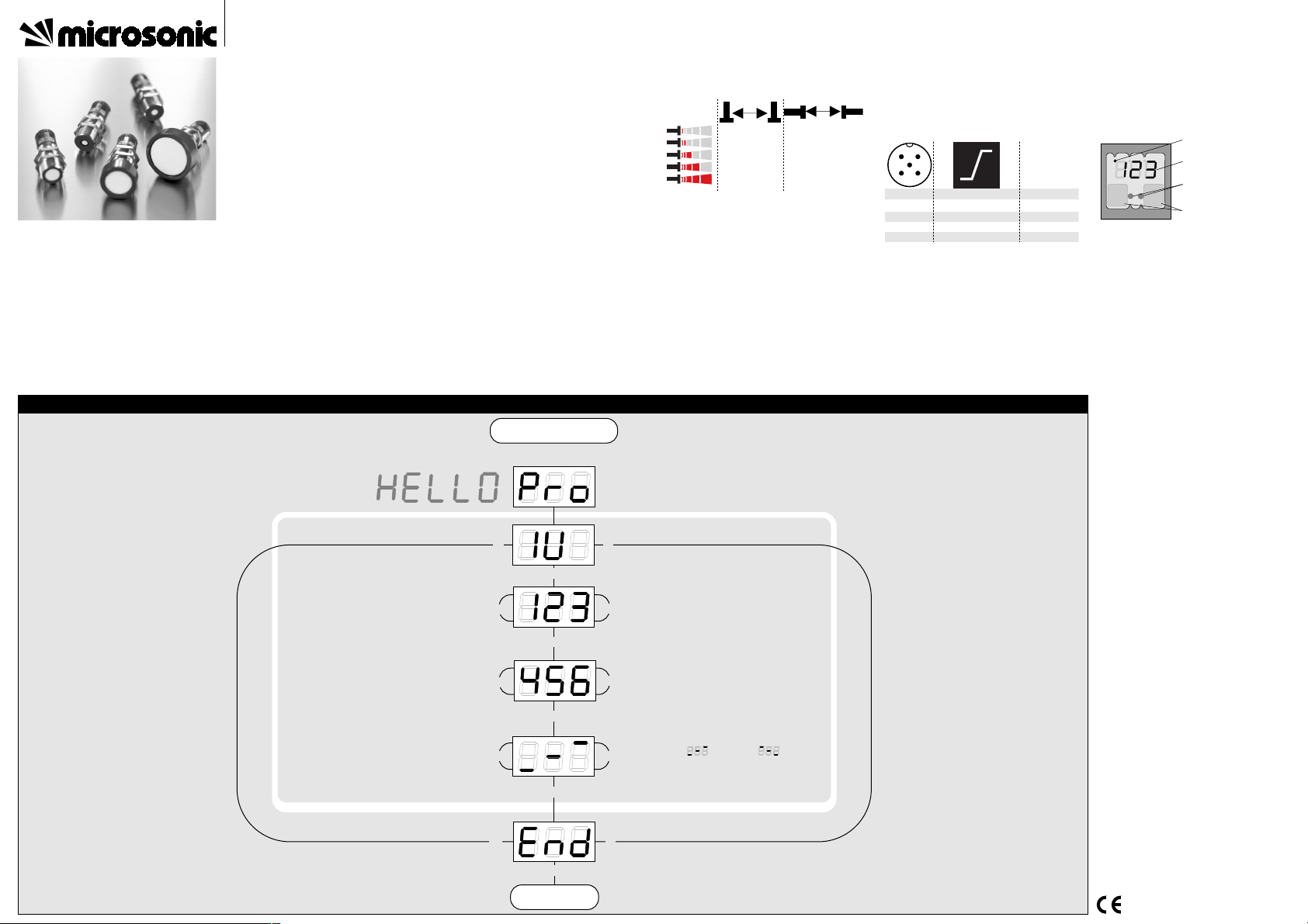
Press T1 and T2 simultaneously for about
3 s until welcome message has passed
T1 + T2
T2
T1
T2
T1
T2
T1
T1 + T2
Set sensor-close window
margin in mm or cm
Choose rising ( ) / falling ( )
output characteristic curve
T1
T2
T1 + T2
T2
T1
T1 + T2
T1 + T2
Set analogue output
Set sensor-distant window
margin in mm or cm
Ready
Start here
Set sensor parameters alternatively numerically using LED-display...
Product description
■ The mic+ sensor with one analogue output measures the distance to an object
within the detection zone contactless. A
signal proportional to distance is created
according to the adjusted window
margings of the analogue characteristic
curve.
■ The sensor automatically detects the load
put to the analogue output and switches
to current output or voltage output respectively.
■ All settings are done with two push-buttons and a three-digit LED-display
(TouchControl).
■ Light emitting diodes (three-colour LEDs)
indicate all operation conditions.
■ Choosing between rising and falling output characteristic is possible.
■ The sensors are adjustable manually using
the numerical LED-display or may be trained using Teach-in processes.
■ Useful additional functions are set in the
Add-on-menu.
■ Using the LinkControl adapter (optional
accessory) all TouchControl and additional sensor parameter settings may be
made by a Windows-Software.
Important instructions for assembly and
application
All employee and plant safety-relevant
measures must be taken prior to assembly,
start-up, or maintenance work (see operation
manual for the entire plant and the operator
instruction of the plant).
The sensors are not considered as safety
equipment and may not be used to ensure
human or machine safety!
The mic+ sensors indicate a blind zone, in
which the distance cannot be measured. The
operating range indicates the distance of the
sensor that can be applied with normal reflectors with sufficient function reserve.
When using good reflectors, such as a calm
water surface, the sensor can also be used up
to its maximum range. Objects that strongly
absorb (e.g. plastic foam) or diffusely reflect
sound (e.g. pebble stones) can also reduce
the defined operating range.
Synchronisation
If the assembly distances shown in Fig.1 for
two or more sensors are exceeded the integrated synchronisation should be used. Connect Sync/Com-channels (pin 5 at the units receptable) of all sensors (10 maximum).
Fig. 1: Assembly distances, indicating syn-
chronisation/multiplex
Multiplex mode
The Add-on-menu allows to assign an individual address »01« to »10« to each sensor
connected via the Sync/Com-channel (Pin5).
The sensors perform the ultrasonic measurement sequentially from low to high address.
Therefore any influence between the sensors
is rejected.
The address »00« is reserved to synchronisation mode and deactivates the multiplex
≥ 0.35 m
≥ 0.40 m
≥ 2.50 m
≥ 2.50 m
≥ 1.10 m
≥ 2.00 m
≥ 8.00 m
≥ 18.00 m
≥ 4.00 m
≥ 30.00 m
A
B
mode. (To use synchronised mode all sensors
must be set to address »00«.)
Assembly instructions
☞ Assemble the sensor at the installation lo-
cation.
☞ Plug in the connector cable to the M 12
connector
Fig. 2: Pin assignment with view onto sen-
sor plug and colour coding of the
microsonic connection cable
Start-up
mic+ sensors are delivered factory made with
the following settings:
■ Rising analogue characteristic
1
3
colour
+U
B
-U
B
brown
blue
4
2
5
-
I/U
black
white
Sync/Com. grey
1
5
2
3 4
■ Window margins for the analogue output set to blind zone and operating
range
■ Measurement range set to maximum range
Set the parameters of the sensor manually or
use the Teach-in procedure to adjust the detect points.
Fig. 3: TouchControl
Operation
mic+ sensors work maintenance free. Small
amounts of dirt on the surface do not influence function. Thick layers of dirt and cakedon dirt affect sensor function and therefore
must be removed.
Note
■ mic+sensors have internal temperature
compensation. Because the sensors heat
up on their own, the temperature compensation reaches its optimum working
point after approx. 30 minutes of operation.
■ If an object is within the set window margins of the analogue output, then LED D1
lights up green, if the object is outside
the window margins, then LED D1 lights
up red.
■ The load put to the analogue output is
detected automatically when turning
supply voltage on.
■ During normal mode operation, the measured distance value is displayed on the
LED-indicator in mm (up to 999 mm) or
cm (from 100 cm). Scale switches automatically and is indicated by a point on
top of the digits. Alternatively a percentage scale may be set in the add-on menu.
In this connection 0% and 100% correspond to the set window margins of the
analogue output.
■ If no objects are placed within the detection zone the LED-indicator shows »- - -«.
■ If no push-buttons are pressed for 20 seconds during parameter setting mode the
made changes are stored and the sensor
returns to normal mode operation.
Show parameters
Tapping push-button T1 shortly during normal mode operation shows »PAr« on the
LED-display. Each time you tap push-button
T1 the actual settings of the analogue output
are shown.
Instruction manual
mic+ Ultrasonic Sensors with
one analogue output
c
m m m %
T 1 D 1 D 2 T
2
measuring range
LED D1 and D2
3-digit
LED-display
Push-buttons T1 and T2
mic+25/IU/TC
mic+35/IU/TC
mic+130/IU/TC
mic+340/IU/TC
mic+600/IU/TC
2004/108/EG
Page 2
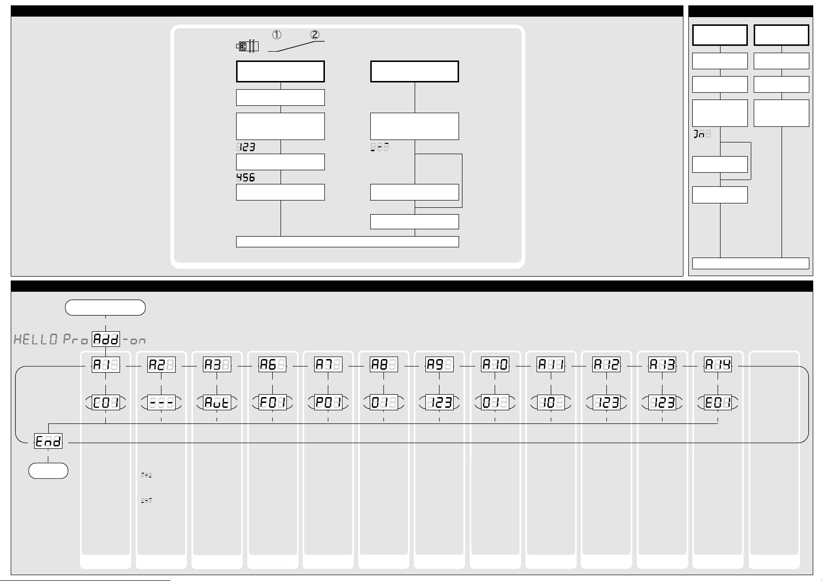
...or with the Teach-in procedure
Set window margins
Place object at position ➀
Press T1 until »IU« is shown
Place object at position ➁
Current measuring
value
Press T1 until »End« is shown
Current measuring
value
Set rising/falling output
characteristic curve
Press T1 until countdown passed
from »- 8 -« to »- 0 -« and symbol
for rising/falling characteristic
is displayed
Sybol rising/falling
characteristis
Sybol falling/rising
characteristis
To change output characteristic
press T1
Normal mode operation
Press T1 and T2 simultaneously until
»End« is displayed
T1 + T2
T1
T2
T1 + T2
Press T1 and T2 simultaneously for about 13 s
until »Add« is shown in the LED-display
T1 + T2
T2
T1
Start here
T2
T1
T1 + T2
Ready
»- - -«: Display in
mm or. cm
» «: Display in
%, 100% at mini-
mum measured value
» «: Display in
%, 100% at maxi-
mum measured value
»C01«: Display
bright
»C02«: Display dimmed
»C03«: Display off
To optimize multiplex speed the highest sensor address
may be set.
Setting range »01«
to »10«
»F00«: no filter
»F01«: standard filter
»F02«: averaging filter
»F03«: foreground
filter
»F04«: background
filter
Defines the strength
of the chosen filter.
»P00«: weak filter
up to
»P09«: strong filter
Affects the size of
the detection zone.
»E01«: high
»E02«: standard
»E03«: slight
Minimum value:
blind zone
Maximum value: nearwindow limit - 1
Low power mode Display mode Choose current/
voltage output
Measurement filter Filter strength Foreground
suppression
Multiplex mode
device addressing
Multiplex highest
device address
»Aut«: automatic
detection of the
load
»U«: voltage output
»I«: current output
»00«: synchronisation
»01« to »10«: sensor
address for multiplex mode
»oFF«: synchronisation deactivated
Minimum value: sensor-distant window
margin
Maximum value: 999
mm for mic+
25/...,mic+35/...,
999 cm for mic+
130/...,mic+340/...,
mic+600/...
Measurement range Calibration
display
Detection zone
sensitivity
Put plane reflector
vertically disposed in
front of sensor: in
an exact distance of
250 mm for mic+
25... and mic+35...
and 900 mm for all
other typs.
Adjust display to
250 mm or 900 mm.
Confirm calibration
with T1 + T2.
T1 + T2
T1
T2
T1 + T2
T2
T1
T1 + T2
T1
T2
T1 + T2
T2
T1
T1 + T2
T1
T2
T1 + T2
T2
T1
T1 + T2
T1
T2
T1 + T2
T2
T1
T1 + T2
T1
T2
T1 + T2
T2
T1
T1 + T2
T1
T2
T1 + T2
T2
T1
T1 + T2
T1
T2
T1 + T2
T2
T1
T1 + T2
T1
T2
T1 + T2
T2
T1
T1 + T2
T1
T2
T1 + T2
T2
T1
T1 + T2
T1
T2
T1 + T2
T2
T1
Delay in seconds
between the detection of an object
and the output of
the measured distance in case of object approach (behaves as on-delay).
"00": 0 s (no delay)
up to
"20": 20 s response
time
Response time
T1 + T2
T1
T2
T1 + T2
T2
T1
Note
Changes in the Add-on
menu may impair the
sensor function.
A6, A7, A8 , A10 , A11,
A12 have influence on
the response time of
the sensor.
Teach-in analogue output
Key lock and factory setting
Activate/deactivate
TouchControl
Reset to factory
setting
Turn supply voltage
OFF
While pressing T1 turn
supply voltage ON
Turn supply voltage
OFF
While pressing T1 turn
supply voltage ON
Keep T1 pressed for
ca. 3 s until »on« or
»off« is displayed
»on« or
»off«
»off« or
»on«
To activate or
deactivate press T1
Don´t press any push-
button for 20 s
Keep T1 pressed for
ca. 13 s until »rESEt«
has passed through
the display
Normal mode operation
◀
◀
Usefull additional functions in Add-on menu (for experienced users only, settings not required for standard applications)
Page 3

*5398*
MV-DO-041945-314765
Technical data
Blind zone
Operating range
Maximum range
Angle of beam spread
0 to 30 mm
250 mm
0 to 65 mm
350 mm
350 mm
Please see detection zone
600 mm
Please see detection zone
0 to 200 mm
1.300 mm
0 to 350 mm
3.400 mm
2.000 mm
Please see detection zone
5.000 mm
Please see detection zone
0 to 600 mm
6.000 mm
8.000 mm
Please see detection zone
Transducer frequency
Resolution
Detection zones
for different objects:
The dark grey areas are determind
with a thin round bar (10 or 27 mm dia.)
and indicate the typical operating range
of a sensor. In order to obtain the light grey
areas, a plate (500 x 500 mm) is introduced
into the beam spread from the side.
In doing so, the optimum angle between
plate and sensor is always employed.
This therefore indicates the maximum
detection zone of the sensor.
It is not possible to evaluate ultrasonic
reflections outside this area.
320 kHz
0,025 mm to 0,10 mm, depending on the
400 kHz
0,025 mm to 0,17 mm, depending on the
analogue window analogue window
Reproducibility
Accuracy
Opperating voltage U
B
± 0,15 %
± 1 % (Temperature drift internal compensated,
± 0,15 %
± 1 % (Temperature drift internal compensated,
may be deactivated1), 0,17%/K without compensation)
9 V to 30 V DC, short-circuit-proof
may be deactivated1), 0,17%/K without compensation)
9 V to 30 V DC, short-circuit-proof
200 kHz
0,18 mm to 0,57 mm, depending on the
120 kHz
0,18 mm to 1,5 mm, depending on the
analogue window analogue window
80 kHz
0,18 mm to 2,4 mm, depending on the
analogue window
± 0,15 %
± 1 % (Temperature drift internal compensated,
± 0,15 %
± 1 % (Temperature drift internal compensated,
may be deactivated1), 0,17%/K without compensation)
9 V to 30 V DC, short-circuit-proof
may be deactivated1), 0,17%/K without compensation)
9 V to 30 V DC, short-circuit-proof
± 0,15 %
± 1 % (Temperature drift internal compensated,
may be deactivated1), 0,17%/K without compensation)
9 V to 30 V DC, short-circuit-proof
Voltage ripple
No-load supply current
Housing
±10 %
≤ 80 mA
±10 %
≤ 80 mA
Brass sleeve, nickel-plated, plastic parts: PBT, TPU;
Ultrasonic transducer: polyurethane foam,
Brass sleeve, nickel-plated, plastic parts: PBT, TPU;
Ultrasonic transducer: polyurethane foam,
Class of protection to EN 60529
Norm conformity
Type of connection
epoxy resin with glass content
IP 67
epoxy resin with glass content
IP 67
EN 60947-5-2
5-pin initiator plug, PBT
EN 60947-5-2
5-pin initiator plug, PBT
±10 %
≤ 80 mA
±10 %
≤ 80 mA
Brass sleeve, nickel-plated, plastic parts: PBT, TPU;
Ultrasonic transducer: polyurethane foam,
Brass sleeve, nickel-plated, plastic parts: PBT, TPU;
Ultrasonic transducer: polyurethane foam,
±10 %
≤ 80 mA
Brass sleeve, nickel-plated, plastic parts: PBT, TPU;
Ultrasonic transducer: polyurethane foam,
epoxy resin with glass content
IP 67
epoxy resin with glass content
IP 67
EN 60947-5-2
5-pin initiator plug, PBT
EN 60947-5-2
5-pin initiator plug, PBT
epoxy resin with glass content
IP 67
EN 60947-5-2
5-pin initiator plug, PBT
Controls
Indicators
Programmable
Operating temperature
2 push-buttons (TouchControl)
3-digit LED-display, 2 three-colour LEDs
2 push-buttons (TouchControl)
3-digit LED-display, 2 three-colour LEDs
Yes, with TouchControl and LinkControl
-25°C to +70°C
Yes, with TouchControl and LinkControl
-25°C to +70°C
Storage temperature
Weight
Response time
1)
Time delay before availibility
-40°C to +85°C
150 g
-40°C to +85°C
150 g
32 ms
< 300 ms
64 ms
< 300 ms
2 push-buttons (TouchControl)
3-digit LED-display, 2 three-colour LEDs
2 push-buttons (TouchControl)
3-digit LED-display, 2 three-colour LEDs
Yes, with TouchControl and LinkControl
-25°C to +70°C
Yes, with TouchControl and LinkControl
-25°C to +70°C
2 push-buttons (TouchControl)
3-digit LED-display, 2 three-colour LEDs
Yes, with TouchControl and LinkControl
-25°C to +70°C
-40°C to +85°C
150 g
-40°C to +85°C
210 g
92 ms
< 300 ms
172 ms
< 300 ms
-40°C to +85°C
270 g
240 ms
< 300 ms
Order No.
Current output 4 – 20 mA
mic+25/IU/TC mic+35/IU/TC
RL ≤ 100 Ω at 9 V ≤ UB ≤ 20 V;
RL ≤ 500 Ω at UB ≥ 20 V
RL ≤ 100 Ω at 9 V ≤ UB ≤ 20 V;
RL ≤ 500 Ω at UB ≥ 20 V
Voltage output 0 – 10 V
1) Can be programmed with TouchControl and LinkControl
Rising/falling output characteristic
RL ≥ 100 kΩ at UB ≥ 15 V, short-circuit-proof
Rising/falling output characteristic
RL ≥ 100 kΩ at UB ≥ 15 V, short-circuit-proof
Rising/falling output characteristic Rising/falling output characteristic
mic+130/IU/TC mic+340/IU/TC
RL ≤ 100 Ω at 9 V ≤ UB ≤ 20 V;
RL ≤ 500 Ω at UB ≥ 20 V
RL ≤ 100 Ω at 9 V ≤ UB ≤ 20 V;
RL ≤ 500 Ω at UB ≥ 20 V
mic+600/IU/TC
RL ≤ 100 Ω at 9 V ≤ UB ≤ 20 V;
RL ≤ 500 Ω at UB ≥ 20 V
Rising/falling output characteristic
RL ≥ 100 kΩ at UB ≥ 15 V, short-circuit-proof
Rising/falling output characteristic
RL ≥ 100 kΩ at UB ≥ 15 V, short-circuit-proof
Rising/falling output characteristic Rising/falling output characteristic
Rising/falling output characteristic
RL ≥ 100 kΩ at UB ≥ 15 V, short-circuit-proof
Rising/falling output characteristic
Analogue output
+U
B
-U
B
IU
Sync/Com
1
2
4
5
3
U
mic+25…
mic+35…
mic+130…
mic+340…
mic+600…
0 cm
5 cm
10 cm
15 cm
20 cm
25 cm
30 cm
35 cm
ausgerichtete Platte
Rohr ø 10 mm
10 cm
5 cm
0 cm
5 cm
10 cm
Plate
Round bar
0 cm
10 cm
20 cm
30 cm
40 cm
50 cm
60 cm
ausgerichtete Platte
Rohr ø 27 mm
20 cm
10 cm
0 cm
10 cm
20 cm
35 cm
Plate
Round bar
0 m
0,4 m
0,8 m
1,2 m
1,6 m
2 m
1,3 m
ausgerichtete Platte
Rohr ø 27 mm
0,8 m
0,4 m
0 m
0,4 m
0,8 m
Plate
Round bar
0 m
0,8 m
1,6 m
2,4 m
3,2 m
4 m
4,8 m
5,6 m
3,4 m
ausgerichtete Platte
Rohr ø 27 mm
1,6 m
0,8 m
0 m
0,8 m
1,6 m
Plate
Round bar
0 m
1,2 m
2,4 m
3,6 m
4,8 m
6 m
7,2 m
8,4 m
ausgerichtete Platte
Rohr ø 27 mm
2,4 m
1,2 m
0 m
1,2 m
2,4 m
Plate
Round bar
The contents of this document are subject to technical changes. Specifications are presented in a descripted way only.
They do not warrant product features.
microsonic GmbH | Hauert 16 | 44227 Dortmund | Germany | telefone: +49 (0)2 31 / 97 51 51-0 | telefax: +49 (0)2 31 / 97 51 51-51 | e-mail: info@microsonic.de | www.microsonic.de
 Loading...