

Page 1
1
3
colour
+U
B
-U
B
brown
blue
4
2
5
-
I/U
black
white
Com. grey
1
5
2
34
≤ 0.35 m
≤ 0.40 m
≤ 2.50 m
≤ 2.50 m
≤ 1.10 m
≤ 2.00 m
≤ 2.50 m
≤18.00 m
≤ 4.00 m
≤30.00 m
A
B
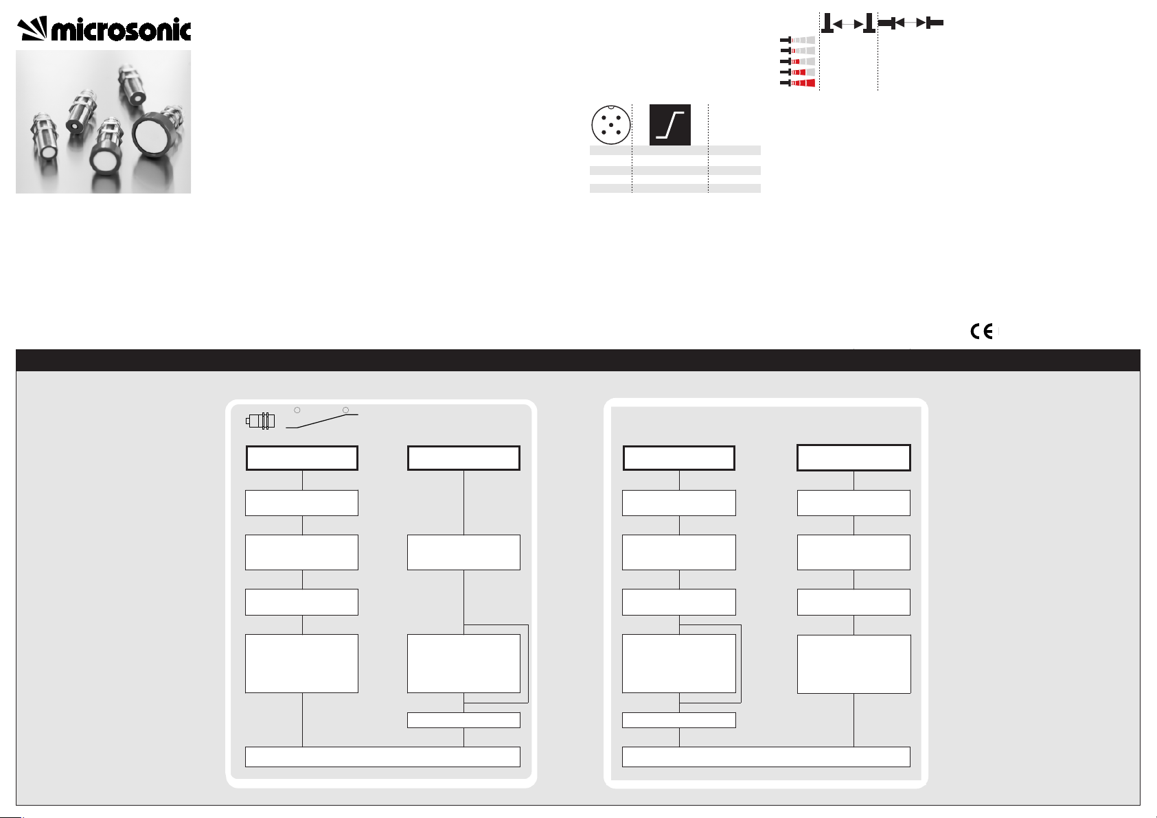
Instruction manual
Set the mic-sensor using the Teach-in procedure
Set window margins
Place object
at position
Connect Com for about
3 s with + U
B
Place object
at position
Connect Com for about
1 s with + U
B
Change Teach-in / Syn-
chronisation
Turn supply voltage OFF
Reset to factory setting
Turn supply voltage OFF
While Com is connected
to - U
B
turn supply
voltage ON
Keep Com connected to
- U
B
for about 3 s
To change operation
mode (Teach-in and Syn-
chronisation)
connect Com
for about 1 s to - U
B
While Com is connected
to - U
B
turn supply
voltage ON
Keep Com connected to
- U
B
for about 13 s
Disconnect
Com from - U
B
before swit-
ching-off
supply voltage
Wait for 20 s
Normal operation mode
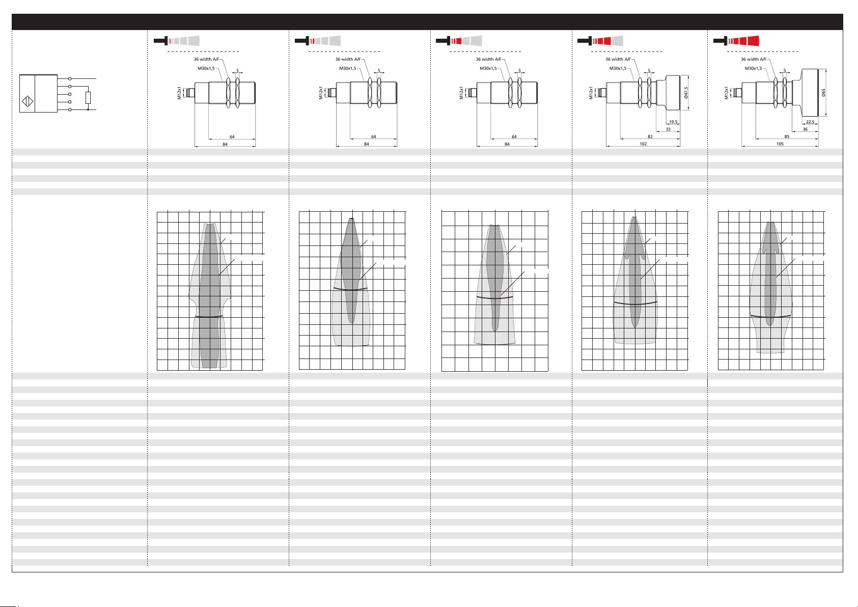
mic Ultrasonic Sensors with
one analogue output
mic-25/IU/M
mic-35/IU/M
mic-130/IU/M
mic-340/IU/M
mic-600/IU/M
Product description
The mic-sensor with one analogue output
measures the distance to an object within
the detection zone contactless. A signal
proportional to distance is created according to the adjusted window
margings of the analogue characteristic
curve.
The sensor automatically detects the load
put to the analogue output and switches
to current output or voltage output
respectively.
Choosing between rising and falling out-
put characteristic is possible.
The sensors are adjustable using Teach-in
processes via the Com-channel (Pin 5).
Using the LinkControl adapter (optional
accessory) all Teach-in and additional sensor parameter settings may be made by a
Windows-Software.
Important instructions for assembly and
application
All employee and plant safety-relevant
measures must be taken prior to assembly,
start-up, or maintenance work (see operation
manual for the entire plant and the operator
instruction of the plant).
The sensors are not considered as safety
equipment and may not be used to ensure
human or machine safety!
The mic-sensors indicate a blind zone, in
which the distance cannot be measured. The
operating range indicates the distance of the
sensor that can be applied with normal reflectors with sufficient function reserve.
When using good reflectors, such as a calm
water surface, the sensor can also be used up
to its maximum range. Objects that strongly
absorb (e.g. plastic foam) or diffusely reflect
sound (e.g. pebble stones) can also reduce
the defined operating range.
Assembly instructions
Assemble the sensor at the installation lo-
cation.
Plug in the connector cable to the M 12
connector.
Abb. 1: Pin assignment with view onto sensor
plug and colour coding of the
microsonic connection cable
Synchronisation
If the assembly distances shown in Fig. 2 for
two or more sensors are exceeded the integrated synchronisation should be used. Connect Sync/Com-channels (pin 5 at the units receptable) of all sensors (10 maximum).
Abb. 2: Assembly distances
Start-up
mic-sensors are delivered factory made with
the following settings:
Rising analogue characteristic
Window margins for the analogue out-
put set to blind zone and operating
range
Maximum detection range set to maxi-
mum range
Set the parameters of the sensor using the
Teach-in procedure to adjust the analogue
chacteristc curve.
Operation
mic-sensors work maintenance free. Small
amounts of dirt on the surface do not influ-
ence function. Thick layers of dirt and caked-on dirt affect sensor function and therefore must be removed.
Note
mic-sensors have internal temperature
compensation. Because the sensors heat
up on their own, the temperature compensation reaches its optimum working
point after approx. 30 minutes of operation.
The load put to the analogue output is
detected automatically when turning
supply voltage on.
If no signal is detected for 20 seconds
during teach-in procedure the made
changes are stored and the sensor returns to normal mode operation.
You can reset the factory settings at any
time, see »Reset to factory setting«.
89/336/EEC
Normal operation mode
Teach-in switched output
Tech-in analogue output Further Settings
Set rising / falling output
characteristic curve
Connect Com for about
13 s with + U
B
◀
To change output
function
connect Com for about
10 s with + U
B
Wait for 10 s
◀
Additional settings
Page 2
*5404*
MV-DO-042098-397179
Technical data
Blind zone
Operating range
Maximum range
Angle of beam spread
Transducer frequency
Resolution, sampling rate
Detection zones
for different objects:
The dark grey areas are determind
with a thin round bar (10 or 27 mm dia.)
and indicate the typical operating range
of a sensor. In order to obtain the light grey
areas, a plate (500 x 500 mm) is introduced
into the beam spread from the side.
In doing so, the optimum angle between
plate and sensor is always employed.
This therefore indicates the maximum
detection zone of the sensor.
It is not possible to evaluate ultrasonic
reflections outside this area.
Reproducibility
Accuracy
may be deactivated1), 0,17%/K without compensation)
may be deactivated1) (0,17%/K without compensation)
may be deactivated1) (0,17%/K without compensation)
may be deactivated1) (0,17%/K without compensation)
Opperating voltage U
B
≤ 80 mA
≤ 80 mA
≤ 80 mA
≤ 80 mA
Response time
1)
RL ≤ 100 Ω at 9 V ≤ UB ≤ 20 V;
RL ≤ 500 Ω at UB ≥ 20 V
RL ≥ 100 kΩ at UB ≥ 15 V, short-circuit-proof
RL ≤ 100 Ω at 9 V ≤ UB ≤ 20 V;
RL ≤ 500 Ω at UB ≥ 20 V
RL ≤ 100 Ω at 9 V ≤ UB ≤ 20 V;
RL ≤ 500 Ω at UB ≥ 20 V
RL ≥ 100 kΩ at UB ≥ 15 V, short-circuit-proof
RL ≥ 100 kΩ at UB ≥ 15 V, short-circuit-proof
RL ≤ 100 Ω at 9 V ≤ UB ≤ 20 V;
RL ≤ 500 Ω at UB ≥ 20 V
RL ≥ 100 kΩ at UB ≥ 15 V, short-circuit-proof
Analogue output
+U
B
-U
B
IU
Com
1
2
4
5
3
U
mic-25…
mic-130…
mic-340…
mic-600…
0 cm
5 cm
10 cm
15 cm
20 cm
25 cm
30 cm
35 cm
Plate
Round bar ø 10 mm
10 cm
5 cm
0 cm
5 cm
10 cm
0 m
0,4 m
0,8 m
1,2 m
1,6 m
2 m
1,3 m
Plate
Round bar ø 27 mm
0,8 m
0,4 m
0 m
0,4 m
0,8 m
0 m
0,8 m
1,6 m
2,4 m
3,2 m
4 m
4,8 m
5,6 m
3,4 m
Plate
Round bar ø 27 mm
1,6 m
0,8 m
0 m
0,8 m
1,6 m
0 m
1,2 m
2,4 m
3,6 m
4,8 m
6 m
7,2 m
8,4 m
Plate
Rund bar ø 27 mm
2,4 m
1,2 m
0 m
1,2 m
2,4 m
The contents of this document are subject to technical changes. Specifications are presented in a descripted way only. They do not
warrant product features.
microsonic GmbH • Hauert 16 • D-44227 Dortmund • Tel: +49 (0)2 31 / 97 51 51-0 • Fax: +49 (0)2 31 / 97 51 51-51 •E-Mail: info@microsonic.de • www.microsonic.de
mic-35…
Voltage ripple
No-load supply current
1) Can be programmed with LinkControl
Class of protection to EN 60529
Operating temperature
Time delay before availibility
Current output 4 – 20 mA
Voltage output 0 – 10 V
Housing
Norm conformity
Type of connection
Controls
Indicators
Programmable
Storage temperature
Weight
Order No.
0 to30 mm
250 mm
350 mm
Please see detection zone
320 kHz
0,18 mm
± 0,15 %
± 1 % (Temperature drift internal compensated,
9 V to 30 V DC, reverse polarity protection
±10 %
Brass sleeve, nickel-plated, plastic parts: PBT;
Ultrasonic transducer: polyurethane foam,
epoxy resin with glass content
IP 67
EN 60947-5-2
5-pin initiator plug,
Brass, nickel-plated
Yes, via Com-channel
No
Yes, with Teach-in and LinkControl
-25°C bis +70°C
-40°C bis +85°C
200 g
32 ms
< 300 ms
mic-25/IU/M mic-35/IU/M
Rising/falling output characteristic
Rising/falling output characteristic Rising/falling output characteristic Rising/falling output characteristic Rising/falling output characteristic Rising/falling output characteristic
0 to 60 mm
350 mm
600 mm
Please see detection zone
400 kHz
0,18 mm
10 cm
0 cm
10 cm
Plate
Round bar ø 27 mm
20 cm
0 cm
10 cm
20 cm
30 cm
35 cm
40 cm
50 cm
60 cm
20 cm
± 0,15 %
± 1 % (Temperature drift internal compensated,
may be deactivated1) (0,17%/K without compensation)
9 V to 30 V DC, reverse polarity protection
±10 %
≤ 80 mA
Brass sleeve, nickel-plated, plastic parts: PBT;
Ultrasonic transducer: polyurethane foam,
epoxy resin with glass content
IP 67
EN 60947-5-2
5-pin initiator plug,
Brass, nickel-plated
Yes, via Com-channel
No
Yes, with Teach-in and LinkControl
-25°C bis +70°C
-40°C bis +85°C
200 g
64 ms
< 300 ms
RL ≤ 100 Ω at 9 V ≤ UB ≤ 20 V;
R
≤ 500 Ω at UB ≥ 20 V
L
Rising/falling output characteristic
R
≥ 100 kΩ at UB ≥ 15 V, short-circuit-proof
L
0 to 200 mm
1.300 mm
2.000 mm
Please see detection zone
200 kHz
0,18 mm to 0,57 mm, depending on the
analogue window analogue window
± 0,15 %
± 1 % (Temperature drift internal compensated,
9 V to 30 V DC, reverse polarity protection
±10 %
Brass sleeve, nickel-plated, plastic parts: PBT;
Ultrasonic transducer: polyurethane foam,
epoxy resin with glass content
IP 67
EN 60947-5-2
5-pin initiator plug,
Brass, nickel-plated
Yes, via Com-channel
No
Yes, with Teach-in and LinkControl
-25°C bis +70°C
-40°C bis +85°C
200 g
92 ms
< 300 ms
mic-130/IU/M mic-340/IU/M
Rising/falling output characteristic
0 to 350 mm
3.400 mm
5.000 mm
Please see detection zone
120 kHz
0,18 mm to 1,5 mm, depending on the
± 0,15 %
± 1 % (Temperature drift internal compensated,
9 V to 30 V DC, reverse polarity protection
±10 %
Brass sleeve, nickel-plated, plastic parts: PBT;
Ultrasonic transducer: polyurethane foam,
epoxy resin with glass content
IP 67
EN 60947-5-2
5-pin initiator plug,
Brass, nickel-plated
Yes, via Com-channel
No
Yes, with Teach-in and LinkControl
-25°C bis +70°C
-40°C bis +85°C
260 g
172 ms
< 300 ms
Rising/falling output characteristic
0 to 600 mm
6.000 mm
8.000 mm
Please see detection zone
80 kHz
0,18 mm to 2,4 mm, depending on the
analogue window
± 0,15 %
± 1 % (Temperature drift internal compensated,
9 V to 30 V DC, reverse polarity protection
±10 %
Brass sleeve, nickel-plated, plastic parts: PBT;
Ultrasonic transducer: polyurethane foam,
epoxy resin with glass content
IP 67
EN 60947-5-2
5-pin initiator plug,
Brass, nickel-plated
Yes, via Com-channel
No
Yes, with Teach-in and LinkControl
-25°C bis +70°C
-40°C bis +85°C
320 g
240 ms
< 300 ms
mic-600/IU/M
Rising/falling output characteristic
 Loading...