

Page 1
Operating Instructions
Ultrasonic proximity switch with
one switched output and IO-Link
interface
lcs+340/F
lcs+600/F
Product description
The lcs+ sensor offers a non-contact
measurement of the distance to an
object which must be positioned
within the sensor’s detection zone.
The switched output is set conditional upon the adjusted detect distance.
Via the Teach-in procedure, the detect distance and operating mode
can be adjusted. One LED indicates
operation and the state of the switched output.
The lcs+ sensors are IO-Link-capable
in accordance with IO-Link specification V1.0.
Safety instructions
Read the operating instructions
prior to start-up.
Connection, installation and ad-
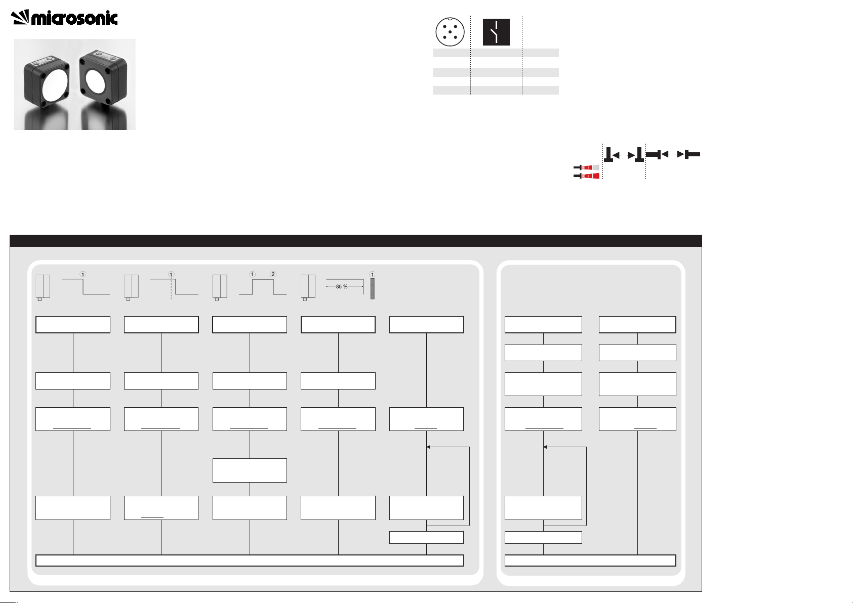
Sensor adjustment with Teach-in procedure
Set detect point
– method A
Place object at position 1.
Press T2 for about
3 s, until both LEDs flash
simultaneously
.
Both LEDs:
flash alternately
Set detect point +8 %
– method B
Place object at position 1.
Press T2 for about
3 s, until both LEDs flash
simultaneously
.
Both LEDs:
flash alternately
Set window mode
Set two way reflective
barrier
Set NOC/NCC
Place object at position 1.
Place reflector at
position 1.
Press T2 for about
3 s, until both LEDs flash
simultaneously
.
Both LEDs:
flash alternately
Press T2 for about
3 s, until both LEDs flash
simultaneously
.
Both LEDs:
flash alternately
Press T2 for about 13 s,
until both LEDs flash
mutually
.
LED D1:
LED D2:
flashes
on: NOC
off: NCC
Activate/deactivate
Teach-in
Switch off operating
voltage.
Reset to factory setting
Switch off operating
voltage.
While pressing T1 turn on
operating voltage.
Keep T1 pressed for about
3 s, until both LEDs flash
simultaneously
.
LED D2:
LED D1:
flash
on: Teach-in
activated
off: Teach-in
deactivated
While pressing T1 turn on
operating voltage.
Keep T1 pressed for about
13 s, until both LEDs
flash mutually
.
Press T2 for about 1 s.
Normal mode operating
Press T2 for about
3 s, until both LEDs flash
mutually
again.
Place object at position 2.
Both LEDs:
flash mutually
Press T2 for about 1 s.
Press T2 for about 10 s.
To change output
characteristic press T2 for
about 1 s.
Wait for 10 s.
To activate/deactivate
Teach-in press T1 for
about 1 s.
Wait for 10 s
Normal mode operating
justments may only be carried out
by qualified staff.
No safety component in
accordance with the EU Machine
Directive.
Use for intended purpose only
lcs+ ultrasonic sensors are used for
non-contact detection of objects.
Installation
Mount the sensor at the place of
fitting.
Connect a connection cable to the
M12 device plug.
Start-up
Connect the power supply.
Carry out sensor adjustment in
accordance with the diagram.
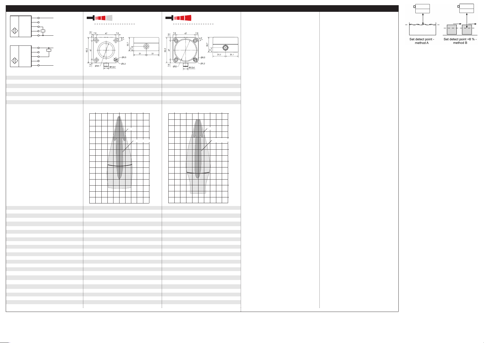
Fig. 1: Pin assignment with view onto sensor
plug and colour coding of the
microsonic connection cables
Factory setting
Switched output on NOC.
Detect distance at operating range.
Operating modes
Three operating modes are available
for the switched output:
1
3
colour
+U
B
-U
B
brown
blue
4
2
5
F
-
black
white
Sync grey
1
5
2
34
Operation with one detect point
The switched output is set when the
object falls below the set detect
point.
Window mode
The switched output is set when the
object is within the set window.
Two-way reflective barrier
The switched output is set when the
object is between sensor and fixed
reflector.
Fig. 2: Assembly distances
≥ 2,00 m ≥ 18,00 m
≥ 4,00 m
≥ 30,00 m
A
B
Synchronisation
If under multiple sensor operation
the assembly distance falls below the
values shown in Fig. 2, the internal
synchronisation should be used. For
this purpose interconnect each pin 5
of max. 10 sensors.
Maintenance
microsonic sensors are maintenancefree. In case of excess caked-on dirt
we recommend cleaning the white
sensor surface.
Notes
The sensors of the lcs+ family have
a blind zone, within which a distance measurement is not possible.
The lcs+ sensors are equipped
with an internal temperature compensation. Due to the sensors self
heating, the temperature compensation reaches its optimum working-point after approx. 30 minutes
of operation.
In the normal operating mode, an il-
luminated yellow LED signals that the
switched output is switched
through.
The lcs+ sensors have a push-pull
switched output.
In the »Two-way reflective barrier«
operating mode, the object has to
be within the range of 0-85 % of
the set distance.
In the »Set detect point – method
A« Teach-in procedure the actual
distance to the object is taught to
the sensor as the detect point. If
the object moves towards the
sensor (e.g. with level control) then
the taught distance is the level at
which the sensor has to switch the
output.
If the object to be scanned moves
into the detection area from the
side, the »Set detect point +8 % –
method B« Teach-in procedure
should be used. In this way the
switching distance is set 8 % further than the actual measured distance to the object. This ensures a
reliable switching distance even if
the height of the objects varies
slightly.
Ultrasonic Sensors
Set switched output
Further Settings
Page 2
Technical data
blind zone
operating range
maximum range
angle of beam spread
0 to 350 mm
0 to 600 mm
see »detection zones«
see »detection zones«
transducer frequency
resolution
reproducibility
120 kHz
0.18 mm
80 kHz
0.18 mm
± 0.15 %
± 0.15 %
accuracy
operating voltage U
B
voltage ripple
±1 % (temperature drift internally compensated; may
±1 % (temperature drift internally compensated; may
no-load current consumption
housing
class of protection per EN 60 529
≤ 60 mA
≤ 60 mA
type of connection
controls
programmable
indicators
synchronisation
operating temperature
storage temperature
weight
switching hysteresis
1)
switching frequency
1)
response time
1)
time delay before availability
1)
norm conformity
order no.
switched output
1) Can be programmed with LinkControl and IO-Link
Push-Pull, UB-3 V, -UB+3 V, I
max
= 100 mA
Push-Pull, UB-3 V, -UB+3 V, I
max
= 100 mA
+U
B
-U
B
F
Com
1
2
4
5
3
Push-Pull output in pnp circuit
U
+U
B
-U
B
F
Com
1
2
4
5
3
Push-Pull output in npn circuit
U
lcs+340...
lcs+600...
detection zones
The dark grey areas represent the zone
where it is easy to recognise the normal
reflector (round bar). This indicates the typical
operating range of the sensors. The light
grey areas represent the zone where a
plate – can still be regognised.. The
requirement here is for an optimum
alignment to the sensor. It is not
for different objects:
good reflector – for instance a
possible to evaluate ultrasonic
reflections outside this area.
3,400 mm
5,000 mm
1.6 m
0.8 m
0 m
0.8 m
Plate
Round bar ø 27 mm
1.6 m
0 m
0.8 m
1.6 m
2.4 m
6,000 mm
8,000 mm
2.4 m
1.2 m
0 m
1.2 m
Plate
Round bar ø 27 mm
2.4 m
0 m
1.2 m
2.4 m
3.6 m
Fig. 4: Setting the detect point for different
directions of movement of the object
The sensor can be reset to its factory setting (see »Further settings«).
Using the LinkControl adapter (op-
tional accessory) and the LinkControl software for Windows, all
Teach-in and additional sensor parameter settings can be optionally
undertaken.
3.2 m
3.4 m
4 m
4.8 m
5.6 m
be deactivated, 0.17 %/K without compensation)
9 V to 30 V DC, reverse polarity protection
±10 %
PBT, Polyester; ultrasonic transducer:
polyurethane foam, epoxy resin with glass content
IP 67
5-pin M12 circular plug, PBT
2 push-buttons
• Teach-in via push-buttons
• LCA-2 with LinkControl
LED yellow/green (switched output set/not set)
internal synchronisation up to 10 sensors
-25°C to +70°C
-40°C to +85°C
180 g
50 mm
4 Hz
microsonic GmbH | Hauert 16 | 44227 Dortmund | Germany | telephone +49 2 31 / 97 51 51-0 | telefax +49 2 31 / 97 51 51-51 | e-mail: info@microsonic.de | www.microsonic.eu The content of this document is subject to technical changes. Specifications in this document are presented in a descriptive way only. They do not confirm any product features.
172 ms
< 380 ms
EN 60947-5-2
lcs+340/F lcs+600/F
NOC/NCC adjustable, short-circuit-proof
be deactivated, 0.17 %/K without compensation)
9 V to 30 V DC, reverse polarity protection
±10 %
PBT, Polyester; ultrasonic transducer:
polyurethane foam, epoxy resin with glass content
IP 67
5-pin M12 circular plug,. PBT
2 push-buttons
• Teach-in via push-buttons
• LCA-2 with LinkControl
LED yellow/green (switched output set/not set)
internal synchronisation up to 10 sensors
-25°C to +70°C
-40°C to +85°C
240 g
100 mm
3 Hz
240 ms
< 450 ms
EN 60947-5-2
NOC/NCC adjustable, short-circuit-proof
4.8 m
6 m
7.2 m
8.4 m
Page 3

The lcs+ sensors are IO-Link-capable
in accordance with IO-Link specification V1.0.
Pointer
In IO-Link mode LinkControl is not
available.
Process data
The lcs+ cyclically transmits the measured distance value with a resolution of 1 mm and the logical state of
the switched output.
Service data
The following sensor parameters
may be set via IO-Link interface using
the IO-Link device description (IODD).
Detect point 1
The switched output is activated
when the distance to an object is
smaller than the present detect point.
Return detect point 1
The switched output is reactivated
when the distance to an object is
greater than the present return detect point (detect point + hysteresis).
Pointer
The return detect point 1 must al-
ways be greater than the detect
point 1.
Detect point 2, return detect point 2
By programming these two detect
distances to a value smaller than the
actual maximum distance the window mode is activated. The window
lies between detect point 1 and detect point 2.
Pointer
The return detect point 2 must al-
ways be smaller than the detect
point 2.
Foreground suppression
Spurious reflections, caused by objects in the foreground of the sensor
may be blocked out by the foreground suppression.
Pointer
The object in the foreground can
cause multiple reflections that lead
to invalid measurement.
The object in the foreground must
not cover the sensor in a way that
the detection zone is influenced.
Maximum range
The value specifies the maximum
measurement range.
Teach-in via push-buttons T1/T2
The push-buttons can be locked/unlocked for the Teach-in procedures.
Set NOC/NCC
The NCC or NOC output function can
be present for the switched output.
Measurement filter
lcs+ ultrasonic sensors provide for a
choice of 5 filter settings:
F00 (no filter)
Each ultrasonic measurement acts in
an unfiltered manner on the output.
F01 (standard filter)
On the object continuously approaching the sensor, the ongoing
interval is immediately taken on
and the output correspondingly
activated. The effect of the object
abruptly moving away from the
sensor is for the existing distance
to be saved for a retaining time
dependent on the filter strength
and for the switched output state
to be maintained.
F02 (Average value filter)
Forms the arithmetic mean across
a number of measurements. The
output is activated in keeping with
the average value. The number of
measurements, from which the
average value is formed, depends
on the selected filter strength.
F03 (
foreground filter
)
This filter reacts very fast on sensor
close measurement values and gives a straightened output on this
sensor close level. Disturbances
from objects in the background or
momentary loss of echoes from
the object to be detected are filtered out.
F04 (
background filter
)
This filter reacts very fast on sensor
far measurement values and gives
a straightened output on this sensor far level. Disturbances from
obstacles in front of the object to
be detected are filtered out.
Filter strength
A filter strength between 0 – weak
filter effect – and 9 – pronounced filter effect – can be selected for each
measurement filter.
Temperature compensation
The temperature compensation improves the measurement accuracy at
changing ambient temperature and
may be deactivated.
Pointer
The measurement accuracy
amounts to 0,17 %/K change of
temperature without compensation.
Switch-on delay
If the switch-on delay is activated,
the switched output will not be set
before the programmed time once
the measurement value falls below
the set detect point. If the measurement value increases to the detect
point again, the switched output will
be reset after 50 % of the programmed on-delay time.
Detection zone sensitivity
The size of the detection zone can be
varied in three steps.
Synchronisation and multiplex in
IO-Link mode
As in SIO mode up to 10 sensors can
be synchronised by interconnecting
the sync-channel (Pin 5) of each sensor. Additionally the multiplex mode
is available.
Multiplex mode device address
In multiplex mode for every sensor
connected via the sync-channel a
unique device address has to be set.
The sensors then perform there
measurement in increasing order of
the device addresses. With multiplex
address »0« the sensors work synchronous, with address »11« synchronisation/multiplex is disabled.
Pointer
In multiplex mode the response
time of each sensor extends corresponding to the number of connected sensors.
Multiplex mode highest address
To optimise the multiplex speed the
highest assigned device address may
be set instead of the default value
»10«.
Interference noise suppression
This filter keeps the state of the output for the time a ultrasonic interference noise, e.g. leaking compressed
air, makes a measurement impossible.
Pointer
The Interference noise suppression
filter extends the measurement cycle of the sensor and for this it's
response time.
Echo quality
To simplify the adjustment of the
sensor towards the measurement object the echo quality can be observed. The value gives back the
strength of the reflected echo.
System commands
With 6 system commands the following settings may be carried out:
Teach-in detect point.
Teach-in detect point +8 %.
Teach-in window mode detect
point 1.
Teach-in window mode detect
point 2.
Teach-in two way reflective barrier.
Reset sensor to factory settings.
IODD file
The latest IODD file you will find
on
the internet under
www.microsonic.de/en/IODD.
For further informations on IO-Link
see www.io-link.com.
IO-Link data
physical layer
SIO mode support
min cycle time
baud rate
format of process data
yes
43 ms
COM 2 (38.400 Bd)
16 Bit, R, UNI16
content of process data
service data IO-Link specific
Bit 0: logical state of switched output,
Bit 1-15: distance value with 1 mm resolution
index
Vendor name
Vendor text
Product name
Product ID
0x10
0x11
0x12
0X13
Product text
service data sensor specific
detect point 1
0x15
index
0x40
format
UINT16
return detect point 1
detect point 2
return detect point 2
0x41
0x42
UINT16
UINT16
0x43
1)
> 58.162:
window mode deactivated
UINT16
foreground suppression
maximum range
Teach-in via push-button T1/T2
set NOC/NCC
0x44
0x45
UINT16
UINT16
0x46
0x47
UINT8
UINT8
measurement filter
filter strength
temperature compensation
switch-on delay
0x48
0x49
UINT8
UINT8
0x4A
0x4B
UINT8
UINT8
detection zone sensitivity
multiplex mode device addressing
multiplex mode highest address
interference noise suppression
0x4C
0x4D
UINT8
UINT8
0x4E
0x4F
UINT8
UINT8
system commands
Teach-in detect point
Teach-in detect point + 8 %
Index
0x02
0x02
Teach-in window mode detect point 1
Teach-in window mode detect point 2
Teach-in two way reflective barrier
reset to factory settings
0x02
0x02
0x02
0x02
observe
distance value
echo quality
Index
0x51
0x50
UINT16
UINT16
1) Distance values as e.g. detect points are given as a multiple of the internal measurement resolution = 0,172 mm (example: 2.038 ≙ 350 mm).
yes
60,8 ms
COM 2 (38.400 Bd)
16 Bit, R, UNI16
access value
Bit 0: logical state of switched output,
Bit 1-15: distance value with 1 mm resolution
index
RRmicrosonic GmbH
www.microsonic.de
RRlcs+
340/F
0x10
0x11
0x12
0X13
R Ultraschall-Sensor
access
R/W
range (dez)
2.038-29.098 (350-4.998 mm)
0x15
index
0x40
format
UINT16
R/W
R/W
2.044-29.104 (351-4.999 mm)
2.049-58.214 (352-4.999 mm)
1)
R/W
2.044-58.214 (351-4.998 mm)
1)
0x41
0x42
UINT16
UINT16
0x43
1)
> 58.162:
window mode deactivated
UINT16
R/W
R/W
0-4.256 (0-1.050 mm)
29.110-58.162 (5.000-9.990 mm)
R/W
R/W
0: deactivated, 2: activated
0: NCC, 2: NOC
0x44
0x45
UINT16
UINT16
0x46
0x47
UINT8
UINT8
R/W
R/W
0-4: F00 - F04
0-9: P00 - P09
R/W
R/W
0: deactivated, 2: activated
0-20: 0-20 s
0x48
0x49
UINT8
UINT8
0x4A
0x4B
UINT8
UINT8
R/W
R/W
1: high, 2: standard, 3: low
0-11: 0: sync, 11: deactivated
R/W
R/W
1-10
0: deactivated, 2: activated
0x4C
0x4D
UINT8
UINT8
0x4E
0x4F
UINT8
UINT8
access value
WW161
162
Index
0x02
0x02
WW163
164
WW165
166
0x02
0x02
0x02
0x02
access
R
R
Index
0x51
0x50
UINT16
UINT16
access value
RRmicrosonic GmbH
www.microsonic.de
RRlcs+
600/F
R Ultraschall-Sensor
access
R/W
range (dez)
3.493-46.564 (600-7.998 mm)
R/W
R/W
3.499-46.570 (601-7.999 mm)
3.505-58.214 (602-7.999 mm)
1)
R/W
3.499-58.214 (601-7.998 mm)
1)
R/W
R/W
0-7.295 (0-1.800 mm)
46.576-58.162 (8.000-9.990 mm)
R/W
R/W
0: deactivated, 2: activated
0: NCC, 2: NOC
R/W
R/W
0-4: F00 - F04
0-9: P00 - P09
R/W
R/W
0: deactivated, 2: activated
0-20: 0-20 s
R/W
R/W
1: high, 2: standard, 3: low
0-11: 0: sync, 11: deactivated
R/W
R/W
1-10
0: deactivated, 2: activated
access value
WW161
162
WW163
164
WW165
166
access
R
R
lcs+340...
lcs+600...
MV-DO-121023-437453
Sensor adjustment in IO-Link mode
 Loading...