

Page 1
Ultrasonic Sensors
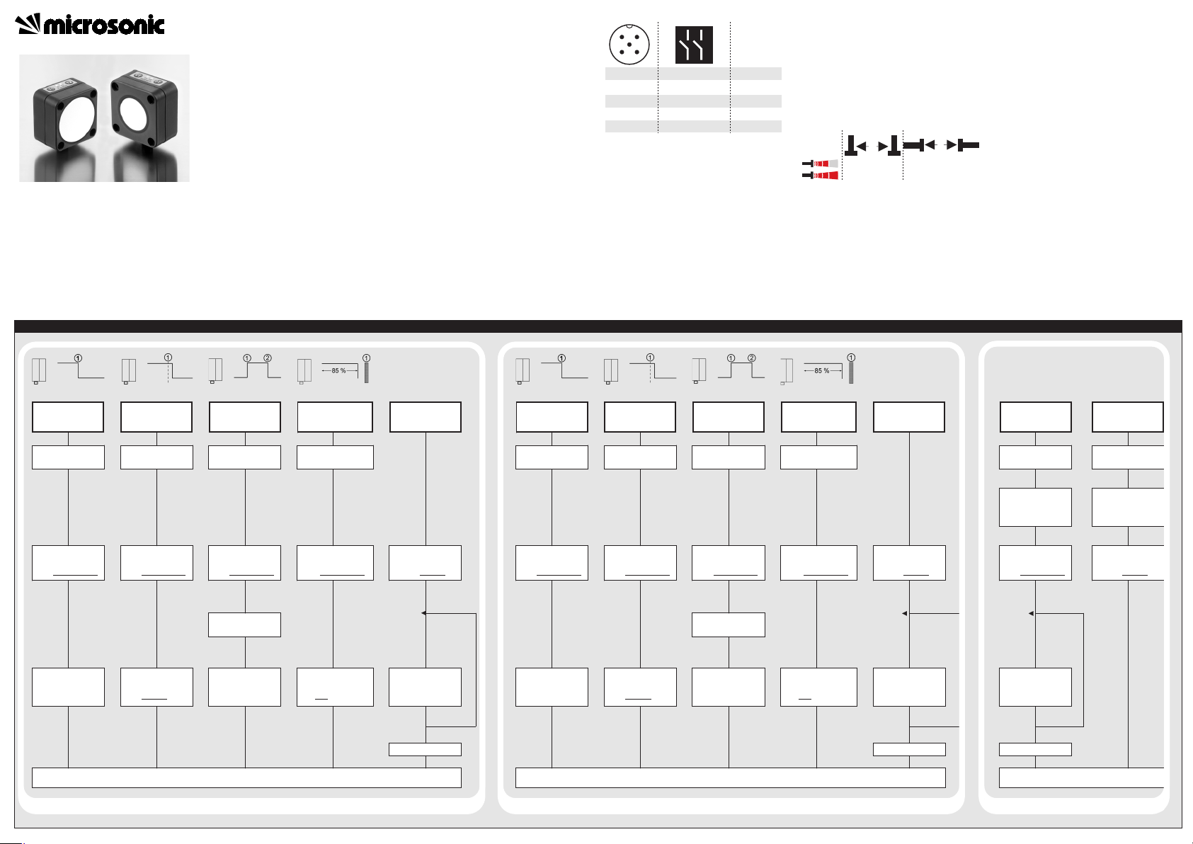
Set switched output
Further Settings
Sensor adjustment with Teach-in procedure
Adjust detect
point D1-
method A
Place object at
position 1.
Press T1 for about
3 s until both LEDs
flash simultaneously
.
Both
LEDs:
flash
mutually
Press T1 for about
1 s.
Adjust detect
point + 8 % D1 -
method B
Place object at
position 1.
Press T1 for about
3 s until both LEDs
flash simultaneously
.
Both
LEDs:
Press T1 for about
3 s until both LEDs
flash mutually
again.
flash
mutually
Adjust window
mode D1
Place object at
position 1.
Adjust two-way
reflective barrier D1
Place reflector at
position 1.
Press T1 for about
3 s until both LEDs
flash simultaneously
.
Press T1 for about
3 s until both LEDs
flash simultaneously
.
Both
LEDs:
Place object at
position 2.
flash
mutually
Both
LEDs:
Press T1 for about
1 s.
flash
mutually
Both
LEDs:
Press T1 for about
10 s until both LEDs
stop
flashing.
flash
mutually
LED D2:
LED D1:
Adjust detect
point D2 method A
Place object at
position 1.
Adjust detect
point + 8 % D2-
method B
Place object at
position 1.
Press T2 for about
3 s until both LEDs
flash simultaneously
.
Both
LEDs:
flash
mutually
Press T2 for about
1 s.
Press T2 for about
3 s until both LEDs
flash simultaneously
.
Both
LEDs:
Press T2 for about
3 s until both LEDs
flash mutually
again.
flash
mutually
Adjust window
mode D2
Place object at
position 1.
Adjust two-way
reflective barrier D2
Place reflector at
position 1.
Set NOC/NCC D2
Press T2 for about
3 s until both LEDs
flash simultaneously
.
Press T2 for about
3 s until both LEDs
flash simultaneously
.
Both
LEDs:
Place object at positi-
on 2.
flash
mutually
Both
LEDs:
Press T2 for about
1 s.
flash
mutually
Both
LEDs:
Press T2 for about
10 s until both LEDs
stop
flashing.
Press T2 for about
13 s until both LEDs
flash mutually
.
flash
mutually
LED D1:
LED D2:
flashes
on: NOC/
off: NCC
To change output
characteristic press T2
for about 1 s.
Normal mode operation
Wait for 10 s.
Activate/deactivate
Teach-in
Turn supply voltage
OFF.
Reset to factory
setting
Turn supply voltage
OFF.
While pressing T1
turn supply voltage
ON.
Press T1 for about
3 s until both LEDs
flash simultaneously
.
LED D2:
LED D1:
flashes
on: Teach-in
activated
off: Teach-in
deactivated
To activate or deacti-
vate Teach-in press T1
for about 1 s.
While pressing T1
turn supply voltage
ON.
Press T1 for about
13 s until both LEDs
flash mutually
.
Wait for 10 s.
1
3
colour
+U
B
-U
B
brown
blue
4
2
5
D2
D1
black
white
Sync/Com grey
1
5
2
34
≥ 2.00 m ≥ 18.00 m
≥ 4.00 m
≥ 30.00 m
A
B
Set switched output D1
Further settings
Set switched output D2
Operating Instructions
Ultrasonic proximity switch with
two switched outputs
lcs+340/DD
lcs+600/DD
Product description
The lcs+ sensor offers a non-contact
measurement of the distance to an
object which must be positioned within
the sensor’s detection zone. The switched outputs are set conditional upon
the adjusted detect distances.
Via the Teach-in procedure, the detect
distances and operating modes can
be adjusted. Two LEDs indicate operation and the state of the switched
outputs.
Optionally all Teach-in and additional
sensor parameter settings can be
made using the LinkControl Adapter
LCA-2 (optional accessory) and the
LinkControl software for windows.
Safety instructions
Read the operating instructions
prior to start-up.
Connection, installation and ad-
justments may only be carried out
by qualified staff.
No safety component in accordance
with the EU Machine Directive.
Use for intended purpose only
lcs+ultrasonic sensors are used for
non-contact detection of objects.
Installation
Mount the sensor at the place of
fitting.
Connect a connection cable to the
M12 device plug.
Start-up
Connect the power supply.
Carry out sensor adjustment in
accordance with the diagram.
Set NOC/NCC D1
Fig. 1: Pin assignment with view onto sensor
plug and colour coding of the
microsonic connection cables
Factory setting
Switched output on NOC.
Detect distance at operating range
and half operating range.
Synchronisation
If under multiple sensor operation
the assembly distance falls below the
values shown in Fig. 2, the internal
synchronisation should be used. For
this purpose interconnect each pin 5
of max. 10 sensors.
Fig. 2: Assembly distances
Maintenance
microsonic sensors are maintenancefree. In case of excess caked-on dirt
we recommend cleaning the white
sensor surface
Notes
The sensors of the lcs+ family have
a blind zone, within which a distance measurement is not possible.
The lcs+ sensors are equipped
with an internal temperature compensation. Due to the sensor's self
heating, the temperature compensation reaches its optimum working-point after approx. 30 minutes
of operation.
During normal operation a yellow
LED signals that the corresponding
output has connected.
If no push-buttons are pressed for
20 seconds during parameter setting mode the made changes are
stored and the sensor returns to
normal mode operation.
Normal mode operation
Press T1 for about
13 s until both LEDs
To change output
characteristic press T1
flash mutually
flashes
on: NOC/
off: NCC
for about 1 s.
Wait for 10 s.
.
Normal mode operation
Page 2
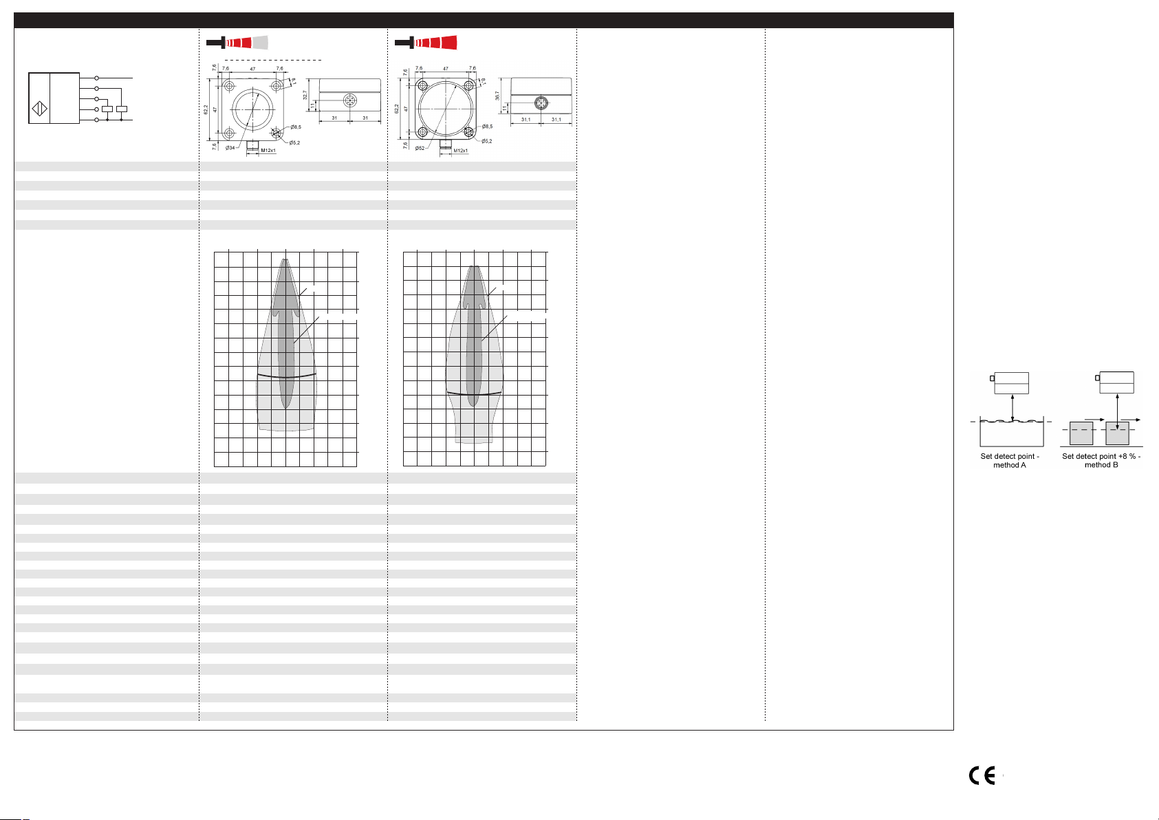
Technical data
blind zone
operating range
maximum range
angle of beam spread
0 to 350 mm
3,400 mm
0 to 600 mm
6,000 mm
5,000 mm
see »detection zones«
8,000 mm
see »detection zones«
transducer frequency
resolution
reproducibility
detection zones
for different objects:
The dark grey areas represent the zone
where it is easy to recognise the normal
reflector (round bar). This indicates the typical
operating range of the sensors. The light
grey areas represent the zone where a
good reflector – for instance a
plate – can still be regognised. The
requirement here is for an optimum
alignment to the sensor. It is not
possible to evaluate ultrasonic
reflections outside this area.
ca. 120 kHz
0.18 mm
ca. 80 kHz
0.18 mm
± 0.15 %
± 0.15 %
accuracy
operating voltage U
B
voltage ripple
±1 % (temperature drift internally compensated; may
be deactivated, 0.17 %/K without compensation)
±1 % (temperature drift internally compensated; may
be deactivated, 0.17 %/K without compensation)
9 V to 30 V DC, reverse polarity protection
±10 %
9 V to 30 V DC, reverse polarity protection
±10 %
no-load current consumption
housing
class of protection per EN 60 529
≤ 60 mA
PBT, Polyester; ultrasonic transducer:
≤ 60 mA
PBT, Polyester; ultrasonic transducer:
polyurethane foam, epoxy resin with glass content
IP 67
polyurethane foam, epoxy resin with glass content
IP 67
type of connection
controls
programmable
5-pin M12 circular plug, PBT
2 push-buttons
5-pin M12 circular plug,. PBT
2 push-buttons
• Teach-in via push-buttons
• LCA-2 with LinkControl
• Teach-in via push-buttons
• LCA-2 with LinkControl
indicators
synchronisation
operating temperature
storage temperature
2 LEDs yellow/green (switched output set/not set)
internal synchronisation up to 10 sensors
2 LEDs yellow/green (switched output set/not set)
internal synchronisation up to 10 sensors
-25°C to +70°C
-40°C to +85°C
-25°C to +70°C
-40°C to +85°C
weight
switching hysteresis
1)
switching frequency
1)
response time
1)
180 g
50 mm
240 g
100 mm
4 Hz
172 ms
3 Hz
240 ms
time delay before availability
1)
norm conformity
order no.
< 380 ms
EN 60947-5-2
< 450 ms
EN 60947-5-2
lcs+340/DD lcs+600/DD
switched output
1) Can be programmed with LinkControl
2 x pnp, UB-2 V, I
max
= 2 x 200 mA
NOC/NCC adjustable, short-circuit-proof
2 x pnp, UB-2 V, I
max
= 2 x 200 mA
NOC/NCC adjustable, short-circuit-proof
+U
B
-U
B
D1
D2
Sync/Com
1
2
4
5
3
2 pnp switched outputs
U
lcs+340…
lcs+600…
0 m
0.8 m
1.6 m
2.4 m
3.2 m
4 m
4.8 m
5.6 m
3.4 m
Plate
Round bar ø 27 mm
1.6 m
0.8 m
0 m
0.8 m
1.6 m
0 m
1.2 m
2.4 m
3.6 m
4.8 m
6 m
7.2 m
8.4 m
Plate
Round bar ø 27 mm
2.4 m
1.2 m
0 m
1.2 m
2.4 m
MV-DO-121024-438041
2004/108/EC
microsonic GmbH | Hauert 16 | 44227 Dortmund | Germany | telefone +49 2 31 / 97 51 51-0 | telefax +49 2 31 / 97 51 51-51 | e-mail: info@microsonic.de | www.microsonic.eu
The content of this document is subject to technical changes. Specifications in this document are presented in a descriptive way only. They do not confirm any product features.
In the »Two-way reflective barrier«
operating mode, the object has to
be within the range of 0-85 % of
the set distance.
In the Teach-in procedure »Set de-
tect point – method A« the actual
distance to the object is taught to
the sensor as the detect point. If
the object moves towards the
sensor (e.g. with level control) then
the taught distance is the level at
which the sensor has to switch the
output.
If the object to be scanned moves
into the detection area from the
side, the Teach-in procedure »Set
detect point +8 % – method B«
should be used. In this way the
switching distance is set 8 % further than the actual measured distance to the object. This ensures a
reliable switching distance even if
the height of the objects varies
slightly.
Fig. 3: Setting the detect point for different
directions of movement of the object
The sensor can be reset to its factory setting (see »Sensor adjustment with Teach-in procedure«).
Optionally all Teach-in and addi-
tional sensor parameter settings
can be made using the LinkControl adapter (optional accessory)
and the LinkControl software for
windows.
 Loading...