

Page 1
Product description
p
y
p
y
Ultrasonic Sensors
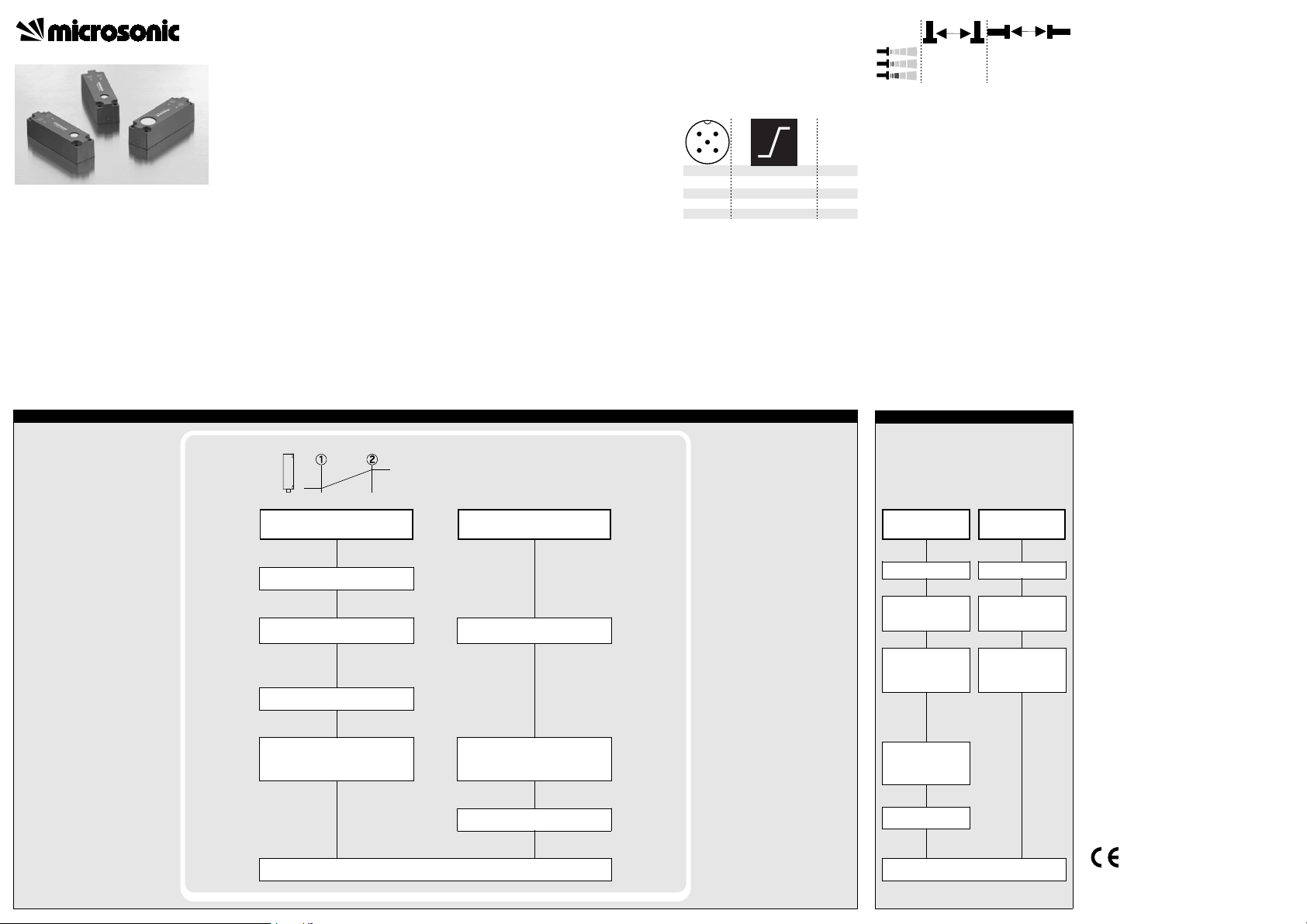
■ The lcs-sensor with one analogue output
measures the distance to an object within
the detection zone contactless. A signal pro-
portional to distance is created according to
the adjusted window margings of the ana-
logue characteristic curve.
■ The sensor automatically detects the
■ Choosing between rising and falling
Instrucion manual
■ Light emitting diodes (three-colour
lcs-Ultrasonic Sensors with
one analogue output
lcs-25/IU/QP
lcs-35/IU/QP
lcs-130/IU/QP
Sensor adjustment with Teach-in procedure
■ The sensors can be trained using Teach-
■ Using the LinkControl adapter (optional
load put to the analogue output and
switches to current output or voltage
output respectively.
output characteristic is possible.
LEDs) indicate the operation conditions.
in processes.
accessory) all sensor parameter settings
may be made by a Windows-Software.
Set window margins
Important instructions for assembly and
application
All employee and plant safety-relevant
measures must be taken prior to assembly,
start-up, or maintenance work (see operation
manual for the entire plant and the operator
instruction of the plant).
The sensors are not considered as safety
equipment and may not be used to ensure
human or machine safety!
The lcs-sensors indicate a blind zone, in
which the distance cannot be measured. The
operating range indicates the distance of the
sensor that can be applied with normal re-
flectors with sufficient function reserve.
When using good reflectors, such as a calm
water surface, the sensor can also be used up
to its maximum range. Objects that strongly
absorb (e.g. plastic foam) or diffusely reflect
sound (e.g. pebble stones) can also reduce
the defined operating range.
Set rising/falling output
characteristic curve
Assembly instructions
☞ Assemble the sensor at the installation
location.
☞ Plug in the connector cable to the M 12
connector.
2
1
34
5
1
3
4
2
5
+U
-U
-
I/U
Com. grey
colour
brown
B
blue
B
black
white
Fig. 1: Pin assignment with view onto sensor
plug and colour coding of the
microsonic connection cable
Assembly distances
The assembly distances shown in Fig.2 for
two or more sensors should not be fallen
below in order to avoid mutual interference.
A
>10 cm
>30 cm
>60 cm >5,4 m
B
>1,0 m
>1,7 m
Fig. 2: Assembly distances
Start-up
lcs-sensors are delivered factory made with
the following settings:
■ Rising analogue characteristic
■ Window margins for the analogue out-
put set to blind zone and operating
range
■ Measurement range set to maximum
range
Set the parameters of the sensor using the
Teach-in procedure.
Lock Teach-in & factory setting
Activate/deactivate
Teach-in
Reset to factory
setting
Operation
lcs- sensors work maintenance free. Small
amounts of dirt on the surface do not influ-
ence function. Thick layers of dirt and caked-
on dirt affect sensor function and therefore
must be removed.
Note
■ lcs-sensors have internal temperature
compensation. Because the sensors heat
up on their own, the temperature com-
pensation reaches its optimum working
point after approx. 30 minutes of opera-
tion.
■ If an object is within the set window
margins of the analogue output, then
LED D1 lights up green, if the object is
outside the window margins, then LED
D1 lights up red.
■ The load put to the analogue output is
detected automatically when turning
supply voltage on.
■ If the signal at the Com line does not
change for 20 seconds during parameter
setting mode the made changes are sto-
red and the sensor returns to normal
mode operation.
■ You can reset the factory settings at any
time, see »Lock Teach-in & factory set-
.
ting«
■ lcs-sensors optional can be programmed
using the LinkControl adapter LCA-2,
see «Optional setting of parameters
using the LinkControl Adapter LCA-2».
Place object at position ➀
Connect Com to +U
simultaneously (ca. 3 s)
Both LEDs:
Place object at position ➁
Connect Com to +U
until both LEDs flash
B
flash
mutually
for about 1 s
B
Normal mode operation
Connect Com to +U
LED D2:
LED D1:
To change output characteristic connect
until both LEDs flash
B
mutually (ca. 13 s)
flashes
an: rising /
aus: falling output
characteristic curve
Com to +U
B
for about 1 s
Wait for 10 s
Turn supply voltage OFF
While Com is connected
to -U
turn on
B
ower supl
Keep Com connected to
-UB until both LEDs flash
simultaneously
(ca. 3 s)
LED D1:
on: Teach-in
activated
off: Teach-in
deactivated
LED D2:
flashes
To activate or
deactivate Teach-in
connect Com to -UB for
about 1 s
Wait for 10 s
Normal mode operation
Set analogue output
Turn supply voltage OFF
While Com is connected
to -U
turn on
B
ower supl
Keep Com connected to
-UB until both LEDs
stop flashing
(ca. 13 s)
89/336/EEC
MV-DO-074366-184870
Page 2
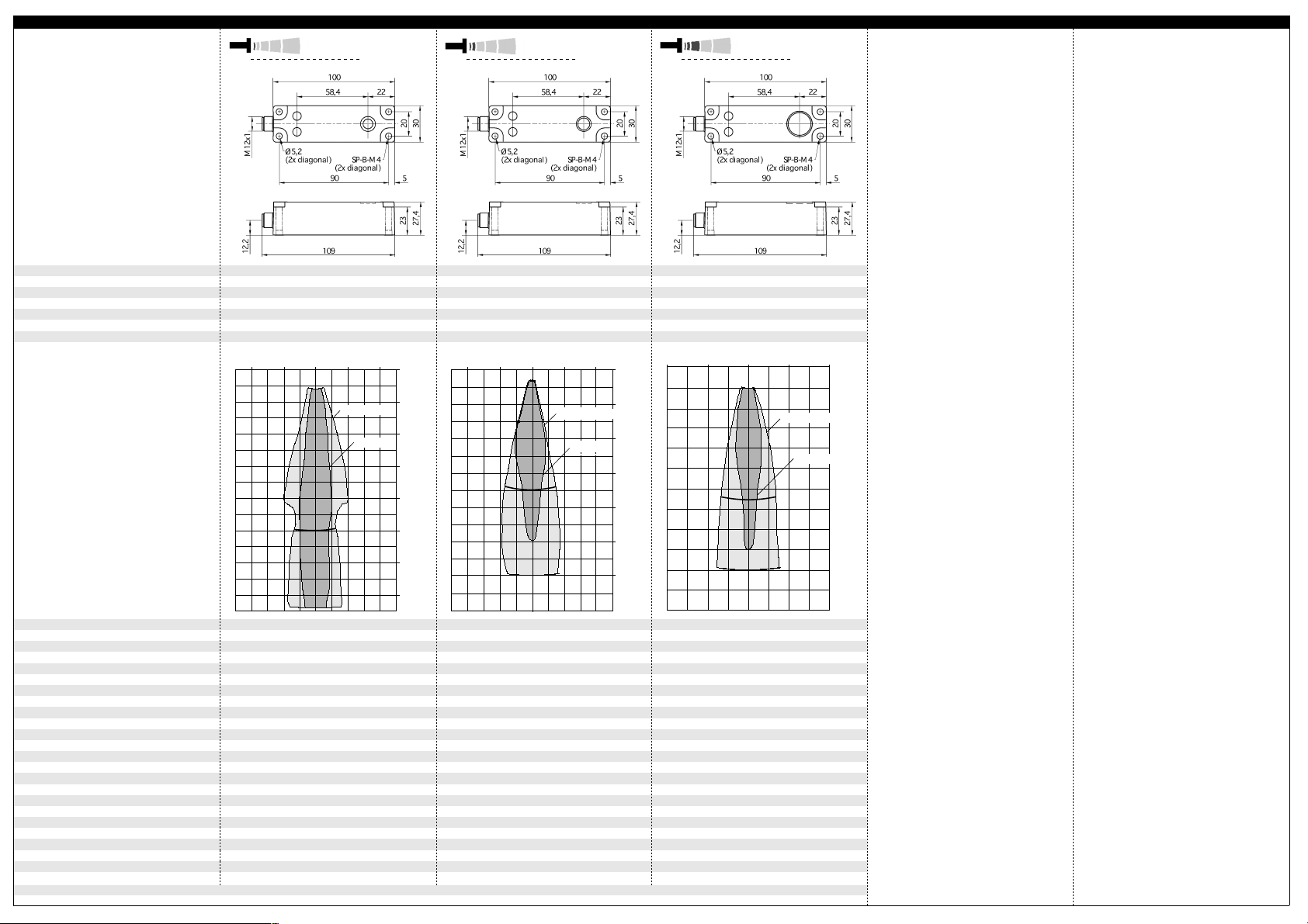
Technical data
p
Blind zone
Operating range
Maximum range
Angle of beam spread
Transducer frequency
Resolution, sampling rate
Reproducibility
Detection zones
The dark grey areas are determined
with a thin round bar (10 mm dia.)
and indicate the typical operating range
of a sensor. In order to obtain the light grey
areas, a plate (100 x 100 mm) is introduced
into the beam spread from the side.
In doing so, the optimum angle between
plate and sensor is always employed.
This therefore indicates the maximum
It is not possible to evaluate ultrasonic
for different objects:
detection zone of the sensor.
reflections outside this area.
lcs-25...
threaded bush
0 to 30 mm
250 mm
350 mm
See detection zone
320 kHz
0,18 mm
± 0,15 % ± 0,15 %
10 cm
10 cm
5 cm
0 cm
5 cm
ausgerichtete Platte
Plate
Rohr ø 10 mm
Round bar
0 cm
5 cm
10 cm
15 cm
20 cm
25 cm
30 cm
35 cm
0 to 65 mm
350 mm
600 mm
See detection zone
400 kHz
0,18 mm
20 cm
10 cm
lcs-35...
threaded bush
0 cm
10 cm
ausgerichtete Platte
Plate
Rohr ø 27 mm
Round bar
20 cm
0 cm
10 cm
20 cm
30 cm
35 cm
40 cm
50 cm
60 cm
0 to 200 mm
1.300 mm
2.000 mm
See detection zone
200 kHz
0,18 mm
± 0,15 %
0,4 m
0,8 m
lcs-130...
threaded bush
0 m
Plate
0,4 m
ausgerichtete Platte
Rohr ø 27 mm
Round bar
0,8 m
0 m
0,4 m
0,8 m
1,2 m
1,3 m
1,6 m
2 m
Operating voltage U
No-load current consumption
Class of protection to EN 60 529
Time delay before availability
Norm conformity
Type of connection
Operating temperature
Storage temperature
Res
Current output 4 – 20 mA
Voltage output 0 – 10 V
1) Can be programmed with LinkControl
Accuracy
Voltage ripple
Housing
Indicators
Programmable
Weight
onse time
Order No.
Temperature drift internal compensated, ≤ 2%, may
be deactivated
9 V to 30 V DC, reverse polarity protection
B
±10 %
< 60 mA
PBT
ultrasonic transducer: polyurethane foam,
epoxy resin with glass content
IP 65
EN 60947-5-2
5-pin M12 initiator plug
2 three-colour LEDs
Yes, with LCA-2 & LinkControl
-25°C to +70°C
-40°C to +85°C
120 g
1)
50 ms
< 300 ms
lcs-25/IU/QP lcs-35/IU/QP
≤ 100 Ω at 9 V ≤ UB ≤ 20 V;
R
L
RL ≤ 500 Ω at UB ≥ 20 V
Rising/falling output characteristic
R
≥ 100 kΩ at UB ≥ 15 V, short-circuit-proof
L
Rising/falling output characteristic Rising/falling output characteristic
1)
(0,17%/K without compensation
Temperature drift internal compensated, ≤ 2%, may
be deactivated 1) (0,17%/K without compensation
9 V to 30 V DC, reverse polarity protection
±10 %
< 60 mA
PBT
ultrasonic transducer: polyurethane foam,
epoxy resin with glass content
IP 65
EN 60947-5-2
5-pin M12 initiator plug
2 three-colour LEDs
Yes, with LCA-2 & LinkControl
-25°C to +70°C
-40°C to +85°C
120 g
70 ms
< 300 ms
RL ≤ 100 Ω at 9 V ≤ UB ≤ 20 V;
RL ≤ 500 Ω at UB ≥ 20 V
Rising/falling output characteristic
RL ≥ 100 kΩ at UB ≥ 15 V, short-circuit-proof
Temperature drift internal compensated, ≤ 2%, may
be deactivated
9 V to 30 V DC, reverse polarity protection
±10 %
< 60 mA
PBT
ultrasonic transducer: polyurethane foam,
epoxy resin with glass content
IP 65
EN 60947-5-2
5-pin M12 initiator plug
2 three-colour LEDs
Yes, with LCA-2 & LinkControl
-25°C to +70°C
-40°C to +85°C
120 g
110 ms
< 300 ms
lcs-130/IU/QP
R
≤ 100 Ω at 9 V ≤ UB ≤ 20 V;
L
RL ≤ 500 Ω at UB ≥ 20 V
Rising/falling output characteristic
R
≥ 100 kΩ at UB ≥ 15 V, short-circuit-proof
L
Rising/falling output characteristic
1)
(0,17%/K without compensation
Page 3

Optional setting of parameters using the LinkControl Adapter LCA-2 (Offline programming)
Start here
T1 T2
+
Press on the LCA-2 simultaneously for about 3 s until welcome message has passed
Offline programming
■ Load Sensor parame-
ters in the LinkControl
Adapter LCA-2
■ Change parameters
and additional functions as described here
■ Write changed para-
meters back into the
lcs- sensor
Please refer to the quick reference guide on the LCA-2.
Setting of additional functions in the LCA-2
Start here
T1 + T2
T1
T1 + T2
T1
T1 + T2
T1
T1 + T2
T1
T1 + T2
Set analogue output
T2
T1 + T2
Ready
T1 T2
Press on the LCA-2 simultaneously for about 13 s until «Add» is shown in the LED-display.
+
T2
Set sensor close window
T2
margin in mm or cm
Set sensor-distant window
T2
margin in mm or cm
Choose rising «» / falling «»
T2
output characteristic curve
T1
T1
T2
T1
T2
T1 + T2
T1 + T2
T2
T2
T1
T1
T1 + T2
T1 + T2
T1
T2
T1 + T2
T1
T2
T1 + T2
T1
T2
T1 + T2
T1
T2
T1 + T2
T1
T2
T1 + T2
T1
T2
T1 + T2
T1
T2
T1 + T2
T1
T2
T1 + T2
T1
T2
T1 + T2
T1
T2
T1 + T2
T1
T2
T1 + T2
T1
T2
T1 + T2
T1
T2
T1 + T2
T1
T2
T1 + T2
T1
T2
T1 + T2
T1
T2
T1 + T2
T1
T2
T1 + T2
T1
T2
T1 + T2
T1 + T2
Ready
T1
No function! No function!»F00«: no filter
Low power mode Display mode Measurement filter Filter strength Foreground
No function! No function! Minimum value: sen-
»Aut«: automatic detection of the load
»U«: voltage output
»I«: current output
Choose current/
voltage output
»F01«: standard filter
»F02«: averaging filter
»F03«: foreground fil-
ter
»F04«: background
filter
Defines the strength
of the chosen filter.
»P00«: weak filter up
to
»P09«: strong filter
Delay in seconds between the detection of
an object and the output of the measured
distance in case of object approach (behaves as on-delay).
"00": 0 s (no delay)
up to
"20": 20 s response
time
Response time
Minimum value: blind
zone
Maximum value: nearwindow limit - 1
suppression
Multiplex mode
device addressing
Multiplex highest
device address
sor-distant window
margin
Maximum value: 999
mm for mic+
25/...,mic+35/...,
999 cm for mic+
130/...,mic+340/...,
mic+600/...
Measurement range
Affects the size of the
detection zone.
»E01«: high
»E02«: standard
»E03«: slight
Detection zone
sensitivity
T2
Note
Changes in the Add-on
menu may impair the sensor
function.
A6, A7, A8 , A10 , A11, A12
have influence on the response time of the sensor.
microsonic GmbH • Hauert 16 • D-44227 Dortmund • Tel: +49 2 31 / 97 51 51-0 • Fax: +49 2 31 / 97 51 51-51 • E-Mail: info@microsonic.de • www.microsonic.de The content of this document is subject to technical changes. Specifications in this document are presented in a descriptive way only. They do not warrant any product features.
 Loading...