

Page 1

*B2204*
LINKCONTROL VERSION 7.6
Programming of ultrasonic sensors
Here you can find the latest LinkControl software:
www.microsonic.de
EW-DO-021316 Rev. 9-267434
Subject to change without notice
Page 2

NOTES
Page 2 of 51
Page 3

CONTENT
Preparation 5
Delivery scope 5
System requirements 5
Installing the Software 6
Connection of the LCA-2 7
Pinning / colour coding 8
Launching the LinkControl software 9
Selecting the COM-Port 10
Directly selection of the COM port 10
Automatically search the COM-Port 10
Reading / writing parameters 11
Reading parameters from a connected sensor 11
Reading parameters from a file 12
Transmit parameters to the sensor 13
Conversion of parameters for the R1 sensors 14
Saving parameters to a file 17
Changing parameters on distance measuring sensors 18
Adjustment of temperature compensation 21
Setting the sensor to its defaults 22
Changing parameters for switching sensors 23
Changing parameters for analogue sensors 25
Filter settings for distance measuring sensors 27
All Sensor families excepting mic-.../M30, lcs, lpc and ucs 27
Sensor families mic-.../M30 und lcs 29
Sensor families lpc und ucs 31
Parameter change in the double sheet control 32
Operating modes 33
Output functions 35
Measuring value writer 35
Parameter change in the Label-/Splice Sensors esp-4 and esf-1 37
Page 3 of 51
Page 4

CONTENT
Teach-in-Methods 38
A) Learn both backing material and label dynamically 38
B) Separate teach-in for backing material and labels 38
C) Learn web material only 38
EasyTeach 38
Parameter change in the web edge sensor bks+ 39
Teach-in-Methoden 40
Analog output setting 40
Switch Output Setting 40
Filter Setting 41
Other Setting 41
Documentation of parameters 42
The parameter list 42
Visualisation of measurements 43
Selecting the mode 43
Numeric presentation 44
Graphic presentation 45
Measurement writer 46
Individual input mask 49
Locking input fields 49
The LinkCopy function 50
LinkCopy with LCA-2 50
Updating LinkControl 51
Page 4 of 51
Page 5

PREPARATION
DELIVERY SCOPE
The LinkControl Adapter is delivered separately or in a plastic case with the following contents:
LCA-2
Adaptor for sensors with cable connection (lcs) incl. cable clamps
Adaptor for power supply incl. cable clamps
Power supply 90-240VAC/24VDC, 625 mA, with 1,8 m cable
four exchangeable AC-plugs for use in Europe, USA, Great Britain and Australia
USB - cable A-plug to B-plug
USB-Stick with LinkControl software and documentation
SYSTEM REQUIREMENTS
Pentium I 166 MHz or higher, 256 MB main memory, 10 MB free space on hard disk drive
Windows 8, Windows 7, Windows Vista, Windows XP
Graphic minimum resolution 800*600, minimum 256 colours
Preparation Page 5 of 51
Page 6

INSTALLING THE SOFTWARE
Start your computer and wait until Windows has booted.
Insert the installation USB stick into the computer
If autostart function is active, installation starts immediately, otherwise open Start.EXE from the
USB stick.
... or get the current LinkControl software from our website and start "Setup.EXE"
Follow the instructions on the screen.
The following files are copied into this directory:
LinkControl.exe executable program file
Updater.exe used for updating LinkControl
LinkC_E.chm English help file
LinkC.ini configuration file for LinkControl
LinkC.lst list of microsonic sensors
Parameter Directory with the default - parameter files of microsonic - Ultrasonic
Sensors
Driver folder with the driver, used for the LCA-2
Page 6 of 51 Preparation
Page 7
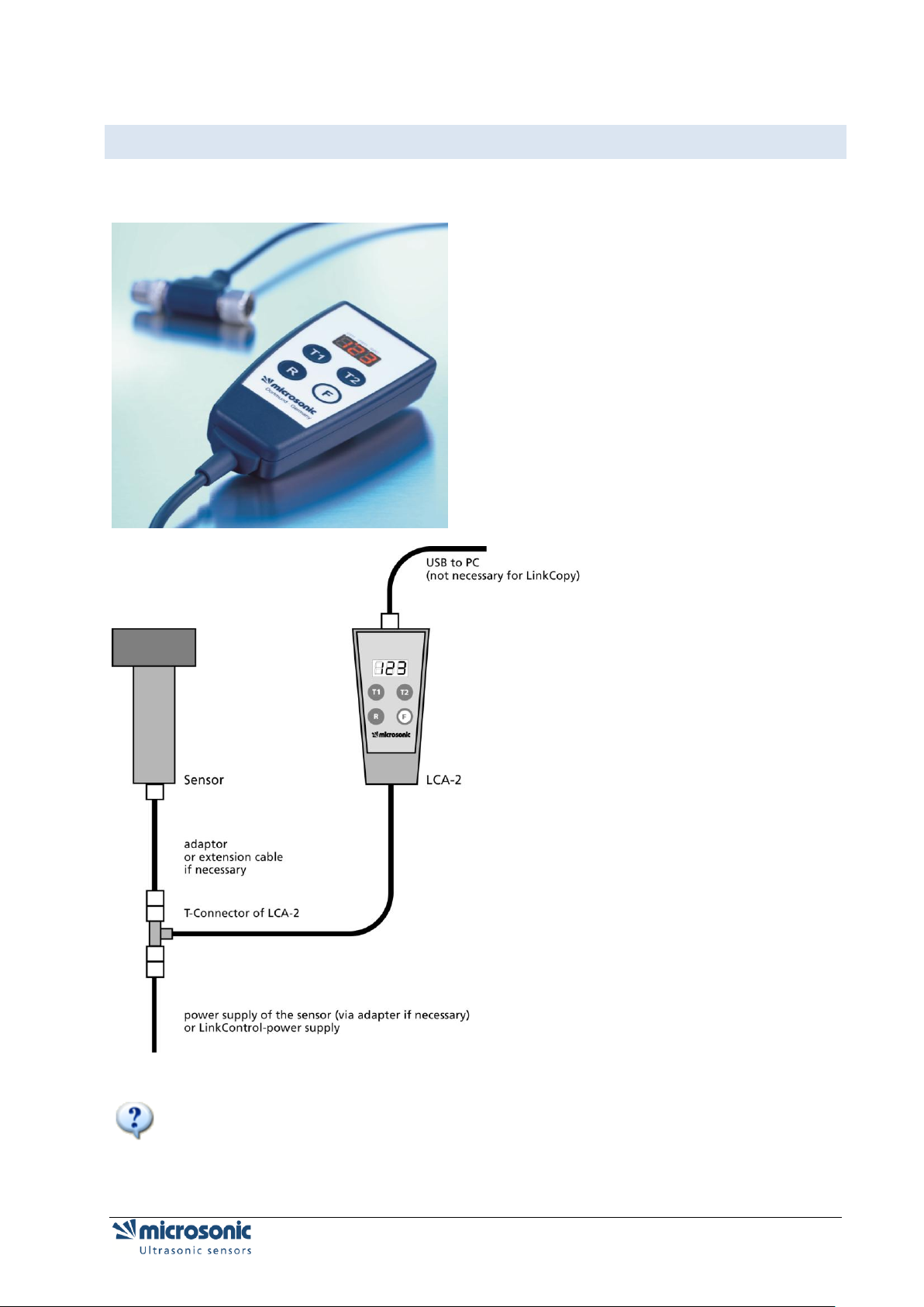
CONNECTION OF THE LCA-2
For further Information see: quick reference guide on the LCA-2
Preparation Page 7 of 51
Page 8

Pin
Standard
colour
coding
Alternative
colour
coding
sensors
with 1
switched
output
sensors
with 2
switched
outputs
sensors
with
analogue
output
sensors with
analogue output +
switched
output
1
brown
brown
+UB
+UB
+UB
+UB
2
white
white
-
output D1
analogue
output
analogue output
3
blue
green
-UB
-UB
-UB
-UB
4
black
grey
output D
output D2
-
output D
5
grey
yellow
communi-
cation *
communi-
cation*
communi-
cation*
communication*
PINNING / COLOUR CODING
For connecting lcs-sensors or mic-sensors with cable to the LinkControl Adapter please use following
adapter.
* With the LinkControl adapter Pin 5 is used for communication between sensor and LinkControl adapter.
In normal operation pin 5 is used for synchronisation and multiplex operation.
Page 8 of 51 Preparation
Page 9
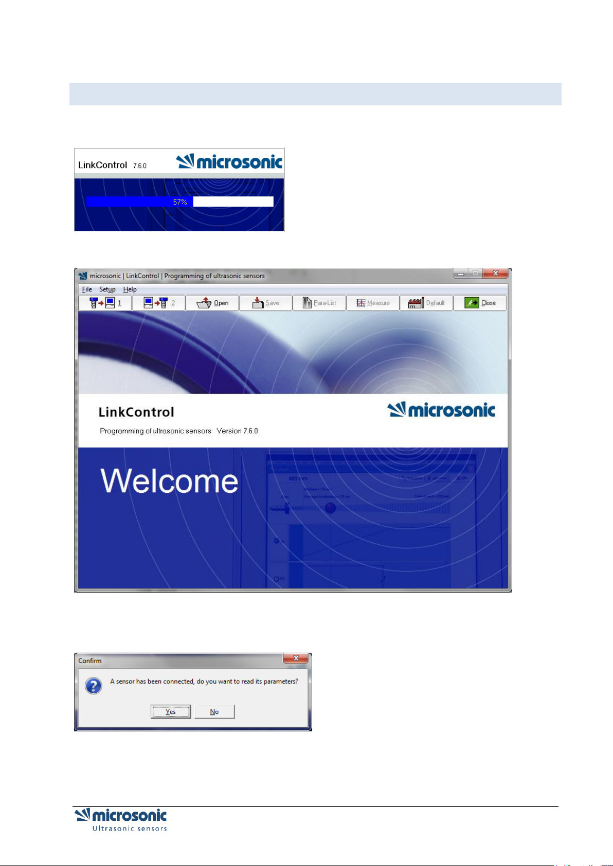
LAUNCHING THE LINKCONTROL SOFTWARE
After starting the software…
the start-up screen appears.
LinkControl checks, if a connected sensor is ready for communication.
If a sensor is recognized, this message appears
You can either read the actual parameters from the connected sensor or open a file with a parameter set.
Preparation Page 9 of 51
Page 10
SELECTING THE COM-PORT
For the communication of LinkControl with the computer, you have to select the COM-Port.
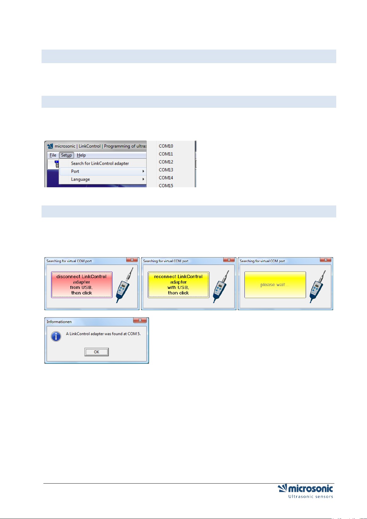
DIRECTLY SELECTION OF THE COM PORT
If you know the used COM-Port,
Use the pull down menu „Setup | Port“ to select the COM-Port 1…23.
AUTOMATICALLY SEARCH THE COM-PORT
If the COM-Port is unknown, LinkControl is able to identify the COM-Port, used by the LinkControl
Adaptor.
Select „Setup | Find LinkControl Adaptor“ and follow the instructions of the software.
Page 10 of 51 Preparation
Page 11
READING / WRITING PARAMETERS
READING PARAMETERS FROM A CONNECTED SENSOR
only for mic-.../M30, lcs and lpc:
Please notice that the sensor does not perform ultrasonic measurements during programming with
LinkCon-trol; thus none of the outputs are served during this period. You are allowed to alter sensor
parameters on an installation or machine under operation using LinkControl only, if you have made sure
that no harmful situation for man and machine may occur when doing so. When in doubt you have to
power down the installation or machine before altering parameters with LinkControl.
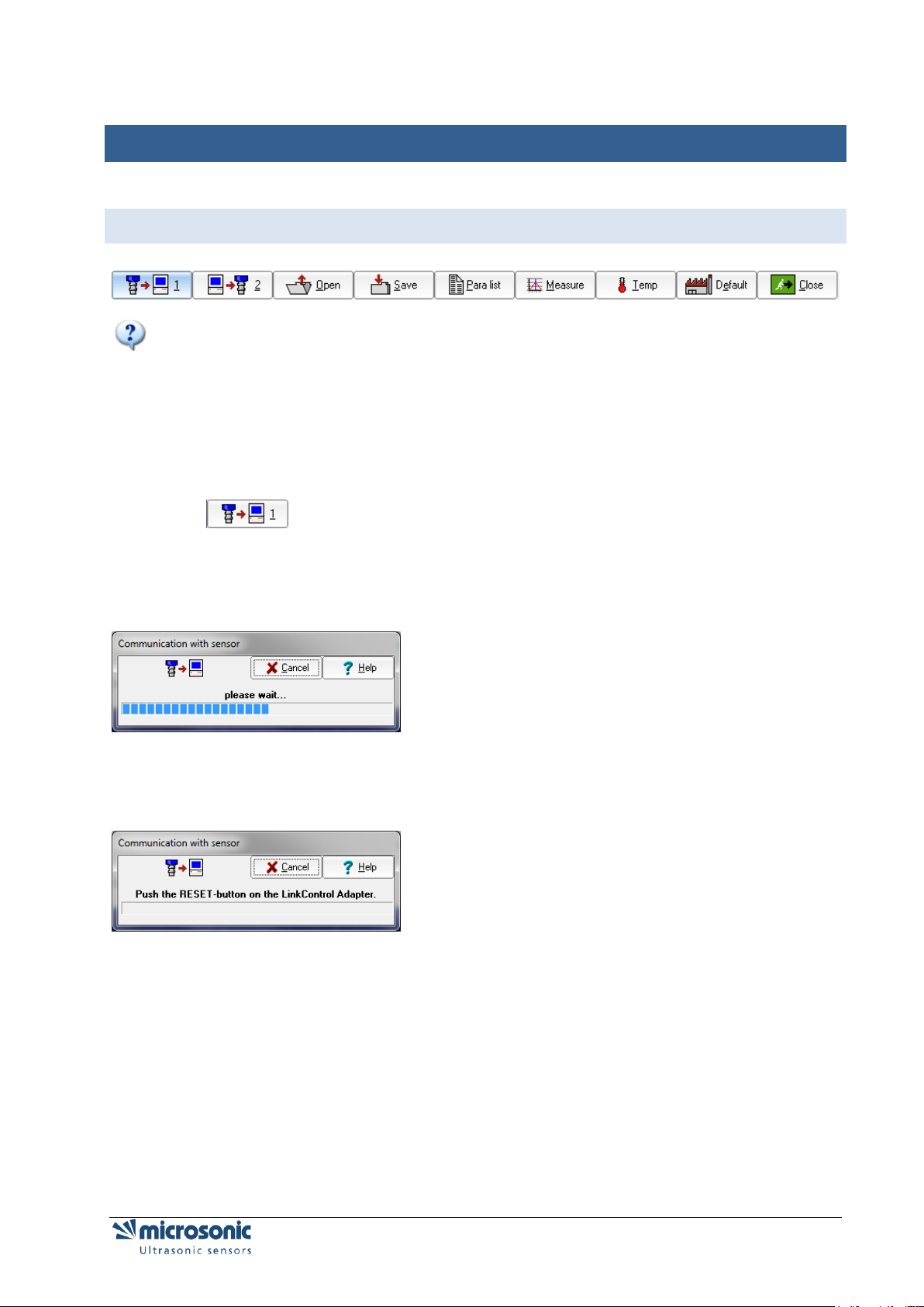
Check for a proper connection of your LinkControl Adapters to your sensor and to your PC and
make sure that the correct port has been selected (COM1...COM23).
Click , for Reading parameters from the sensor and confirm the security query.
or
switch on the sensor and confirm the security query.
All parameters are read from the sensor and transferred to the input mask of the LinkControl software
after-wards.
If the following message occurs,
push the RESET button on the LinkControl Adaptor.
If still the parameters cannot be read from the sensor, please check, whether
a sensor capable for LinkControl is connected
the sensor gets its power supply via the LinkControl adaptor (LED's on sensor have to be
illuminated)
the USB - connection to the PC is made properly
the correct port has been selected within the LinkControl software
Reading / writing parameters Page 11 of 51
Page 12
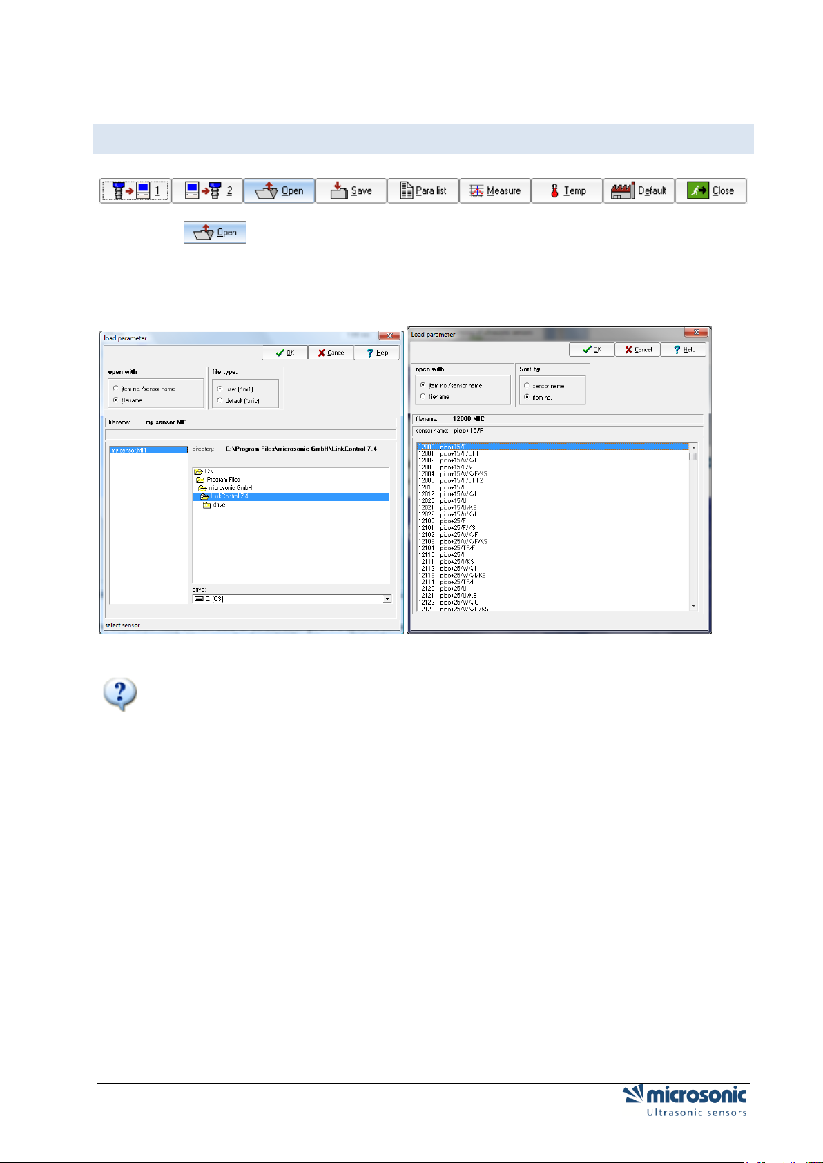
READING PARAMETERS FROM A FILE
Click
select, whether you want to load parameters out of a file…
or load the default parameter files of a specified sensor by sensor name by his sensor name and
his item number.
select the sensor respectively the parameter file and confirm by OK.
Parameter files with the extension *.MIC contain data for default settings of the specific sensor.
These files have been established by microsonic. You may alter these basic settings and store them
afterwards with the extension *.MI1 under the same or a different name. Thus the files with the default
settings will not be corrupted.
Page 12 of 51 Reading / writing parameters
Page 13
TRANSMIT PARAMETERS TO THE SENSOR
All changes that you have made in the input masks, are only temporarily stored within the
LinkControl program. You have to transfer the data to the sensor and / or save it as a file on the hard disc
of your PC or on a floppy disc.
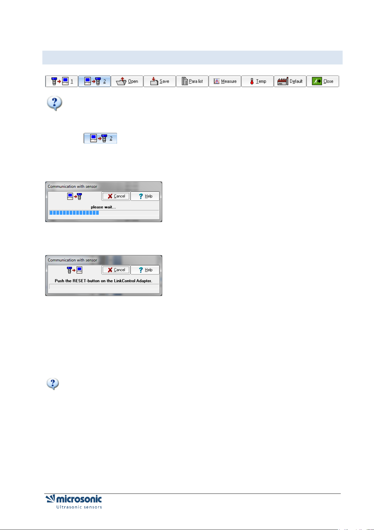
Click for sending the parameters to the sensor
Confirm the security query
It is checked in advance whether the connected sensor matches the sensor type, which is indicated in the
in-put mask. Subsequently the altered parameters are transferred to the sensor.
If the following message occurs,
push the RESET button on the LinkControl adaptor.
If still the parameters cannot be written to the sensor, please check, whether
a sensor capable for LinkControl is connected
the sensor gets its power supply via the LinkControl adapter (LED's on sensor have to be
illuminated)
the USB connection to the PC is properly made
the correct port has been selected within the LinkControl software
Also: Reading parameters from a connected sensor
If the LinkControl software realises, that the selected sensor type does not match the connected sensor
type, the transfer of parameters is inhibited.
Reading / writing parameters Page 13 of 51
Page 14
CONVERSION OF PARAMETERS FOR THE R1 SENSORS
The mic-XX/YY/HV/M30 and lcs-XX/YY/HV/QP ultrasonic sensors have been revised in terms of hardware and software. The revised sensors are additionally marked with "R1" in the product designation:
mic-101/IU/HV/M30 becomes mic-101/IU/HV/M30 R1
These R1 sensors are mechanically, electrically and acoustically downward-compatible with the old Ics
sensors.
Programming via the LinkControl software has changed for the new R1 sensors.
The parameter files of the R1 sensors are not compatible with those of the old sensors.
The R1 sensors no longer support the LinkCopy function via the master sensor.
The filter settings have changed.
To transfer the sensor settings of an old Ics sensor to a new R1 sensor, you can read out the sensor set-
tings from the old Ics sensor via the LinkControl software (or load your parameter file from the hard disk)
and then write the settings into the connected R1 sensor. Version 7.3.0 or higher of the LinkControl software converts the parameters of the old sensor and indicates whether the conversion was successful.
This procedure is described below.
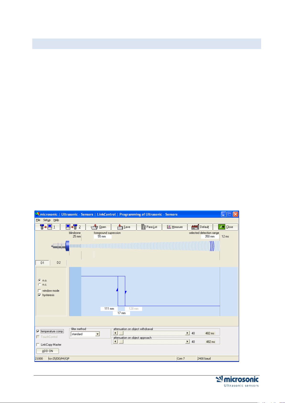
Connect the old sensor with the sensor settings to be converted to the LinkControl adaptor and
read out the parameters
or
open the parameter file from the hard disk.
The following screenshot shows the sensor settings of an Ics-25/DD/HV/QP as an example:
Page 14 of 51 Reading / writing parameters
Page 15
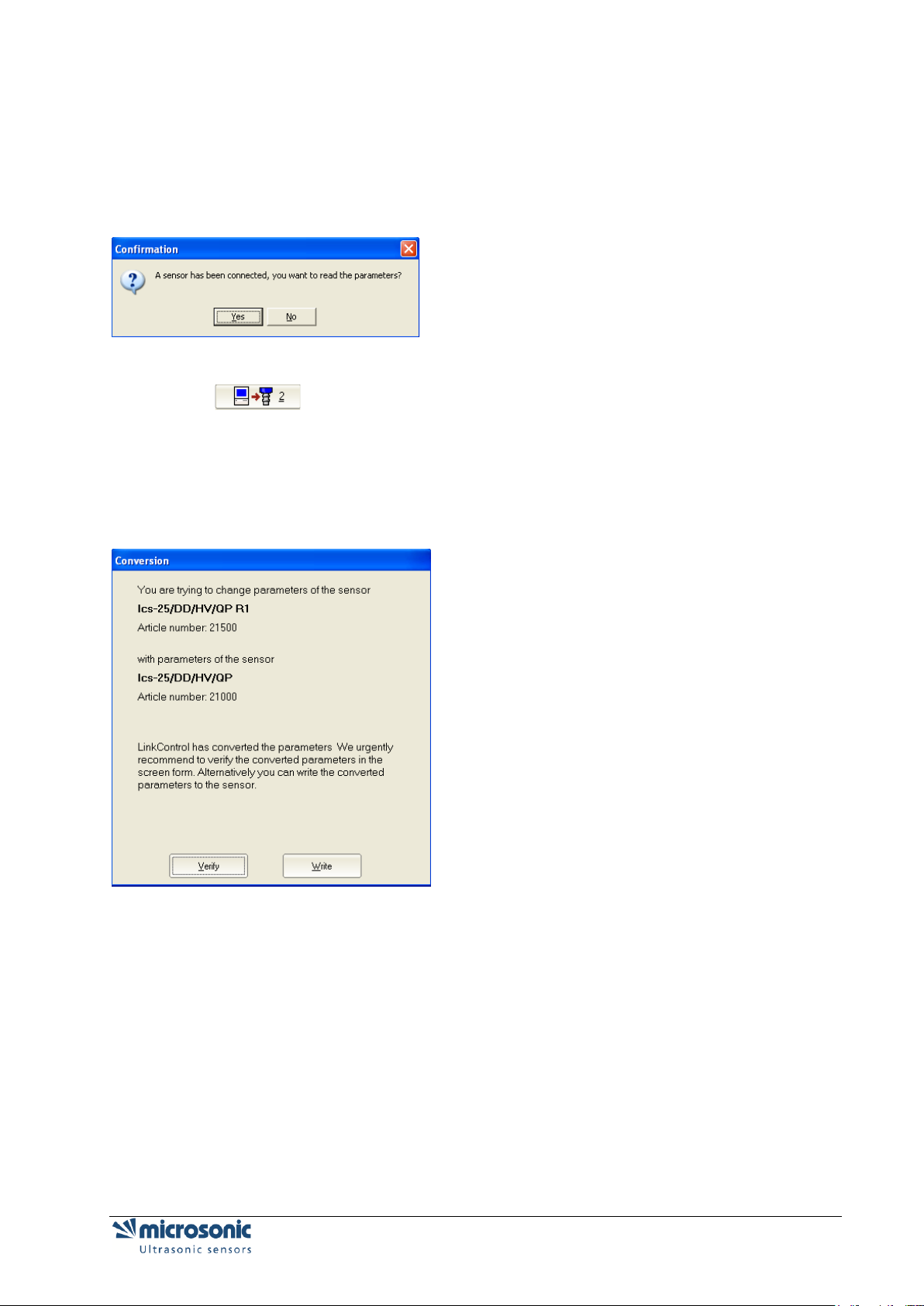
Connect an R1 sensor of the same type to the LinkControl adaptor (Ics-25/DD/HV/QP R1 shown
in the example).
LinkControl automatically recognises the connection of a different sensor and asks you whether the
parameters of this sensor are to be read out.
Click "No" to cancel the process
Click
LinkControl now converts the parameters of the old sensor into new parameters for the R1 sensor. If
LinkControl was able to convert all parameters, you are offered the option of either directly writing the
converted parameters into the new sensor or checking the converted parameters on the screen mask:
Click the button "Verify" to verify the converted parameter first, or click "Write" to write the
converted parameter directly into the new sensor.
Reading / writing parameters Page 15 of 51
Page 16
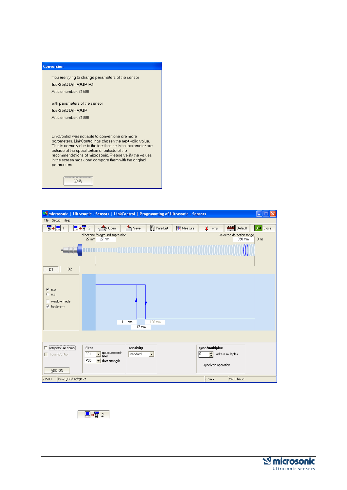
If LinkControl was not able to convert all parameters, the software asks you to check the converted
parameters on the screen mask:
Click the button "Verify".
Check the converted parameters.
Click , to transfer the checked parameters to the new sensor.
Check the sensor settings during ongoing measuring.
If required, save the converted sensor settings as a new converted parameter file to your hard
disk.
Page 16 of 51 Reading / writing parameters
Page 17

SAVING PARAMETERS TO A FILE
Click
Select a file name of your own and confirm by pressing OK.
When saving parameter data only the file name extension *.MI1 is accepted (to mark the file as
user file), to preserve the default parameter files (*.MIC).
Reading / writing parameters Page 17 of 51
Page 18

CHANGING PARAMETERS ON DISTANCE MEASURING SENSORS
Depending on the connected sensor (or according to the loaded sensor file) the input mask may
vary in its appearance. All changes which you make in the input mask are only temporarily stored in the
PC. Subsequently these new settings have to be be transferred to the sensor and / or be stored
permanently on the hard disc of your PC.
All general parameters can be set on switching sensors as well on analogue ultrasonic sensors.
The numeric values have to be input in mm and can be edited by keyboard.
Additional the values of foreground suppression, switching distances, hysteresis points and window
margins can be changed by clicking and dragging the edge point (mouse pointer changes to ) .
BLINDZONE
Since the ultrasonic sensor uses the same transducer element for both sending and receiving, the sensor
can-not start to read in echo signals before the oscillations of the strong sending pulse have calmed
down. This results in a blind zone which is typical for an ultrasonic sensor. The usable measurement
range begins right after the blind zone. The target distance should not be less than the blind zone, as this
may result in mismeasurements. The size of the blind zone varies with the different maximum detection
ranges of different models; the blind zone is sensor-immanent and cannot be influenced by the user.
FOREGROUND SUPPRESSION
The foreground suppression represents an artificial enlargement of the blind zone, i.e. the measurement
range begins after the value of the foreground suppression instead of the blind zone. All echo signals,
which arrive between sensor and foreground suppression, are ignored. You can use this feature to
suppress small unwanted targets, which are located in the vicinity of the sensor.
SELECTED DETECTION RANGE
The selected detection range determines the maximum distance that can be measured. Using the default
set-tings the selected detection range is set to the maximum detection range of a sensor type. The
maximum detection range is the recommended - physically reasonable - detection range, up to which the
sensor can be used (assuming good reflection properties of the target object). The nominal detection
range, which is indicated in the technical data sheets of microsonic, represents on the other hand the
typical detection range where the sensor still functions according to its technical specifications - even on
reflectors with critical reflection properties (functional reserve).
The selected detection range takes effect on the repetition rate of sensor measurements. The time for a
single ultrasonic measurement, resulting from the selected detection range, is displayed above the
correspondent input field. If you decrease the selected detection range you will increase the measurement
repetition rate of the sensor. Please notice however that values below the nominal detection range of the
specific sensor type might affect the sensor function due to double reflections. Normally there is no need
to select a value for the selected detection range other than given by the default settings.
Page 18 of 51 Changing parameters on distance measuring sensors
Page 19

TEMPERATURE COMPENSATION
The velocity of sound in air is temperature dependent. The dependency can roughly be specified as 0,17
%/°C. To compensate this temperature influence, the temperature is internally measured and a correction
factor is calculated for the time-of-flight of echoes. The internal temperature compensation can be enabled
/ disabled by the check box Temp. Comp..
TOUCHCONTROL
The ultrasonic sensors of the mic series are equipped with a control panel to manually adjust basic sensor
parameters via two push buttons (TouchControl). If the mic sensors should only be adjustable using the
Link-Control adapter, the control panel may be locked by unmarking the check box TouchControl. This is
helpful, if you want to prevent unauthorised, manual adjustment of sensors.
only for mic-.../M30: If on switching sensors the option window mode is activated, or on analogue
sensors the option end value delimiter, TouchControl is automatically reset, to prevent a subsequent
change of these complex settings via the control panel.
SENSITIVITY
Only for sensors mic+.../TC or mic-...M from 2004!
CURRENT SAVING-MODE
Only for sensors mic+.../TC or mic-...M from 2004!
For the reduction of the current consumption, one can dim or switch off the display. For a further reduction
of the current consumption you can deactivate the synchronisation.
SYNC/MULTIPLEX
Only for sensors mic+.../TC, mic-...M from 2004 and pico+
If the assembly distances for two or more sensors are exceeded, the integrated synchronisation should be
used. Within the multiplex operation every sensor can be assigned sensor an individual device address
between 1 and 10. The sensors perform the ultrasonic measurement sequentially from low to high
address. Therefore any influence between the sensors is rejected.
The device address >0< is for the synchronous working reserved and deactivates the multiplex mode. For
the synchronous working all sensors, the device address has to be >0<.
DISPLAY MODE
Only for sensors mic+.../TC or mic-...M from 2004
On sensors with analogue output the display mode of the sensor-display can be changed.
Changing parameters on distance measuring sensors Page 19 of 51
Page 20

mm: the measured distance value is indicated in mm and/or cm
0...100%: the measured distance value is indicated as percentage value of the analogous
characteristic, be-gun from the sensor-near vertex up to the sensor-far vertex
100...0%: the measured distance value is indicated as percentage value of the analogous
characteristic, be-gun from the sensor-far vertex up to the sensor-near vertex
NOISE INTERFERENCE FILTER
Only for pico+ or lcs+ sensors
Interfering ultrasonic signals, which are not produced by the sensor itself can be suppressed by the
activation of the noise interference filter.
Page 20 of 51 Changing parameters on distance measuring sensors
Page 21

ADJUSTMENT OF TEMPERATURE COMPENSATION
Only for sensors mic+.../TC, ,mic-...M from 2004 and pico+
For very precise measurements the temperature compensation can be adjusted. For that a sound-hard
reflector is positioned in the exactly measured distance to the sensor and sends this distance information
to the sensor.
Install the sensor according to operating manual at his later field and you turn on the operating
voltage. Wait approx. 30 minutes until the sensor reached his final operating temperature.
Position a flat plate (for example Epoxy-, Metal-, wooden board or smooth carton) with the least
measurements 100 x 100 mm in a normal way achieved to the sensor into the sonic field. Position
the plate for instance in the field of the detection range of the sensor, if this is not possible into the
maximally possible distance.
Measure the distance as exactly as possible with a tape measure between sensor membrane and
plate. Enter the determined value into the input field >real distance<.
The following step is not to be cancelled. Assure that the steps 1...3 were carried out cor-rectly.
Push the button >Execute<. The internal temperature compensation of the sensor is optimally
tuned by your real conditions of use. Pay attention, that the sensor due to his heat masses can
follow temperature changes not inertness-free.
Changing parameters on distance measuring sensors Page 21 of 51
Page 22

SETTING THE SENSOR TO ITS DEFAULTS
Click
Confirm the security query.
All parameters that you changed, will be set to its default values located in the default parameter files
(*.MIC).
All changes that are made in the input mask are temporarily stored in the PC program only.
Subsequently these new settings have to be transferred to the sensor (see: Transmit parameters to the
sensor).
Page 22 of 51 Changing parameters on distance measuring sensors
Page 23

CHANGING PARAMETERS FOR SWITCHING SENSORS
microsonic ultrasonic sensors with pnp- or npn switching output are available as versions with one or two
outputs (S1 and S2). On sensors with two switching outputs the trip points can be set independent from
each other.
N.O. / N.C (MAKE / BREAK BEHAVIOUR)
For each switching output a Make or Break behaviour can be selected individually (make = n.o. = normally
open, break = n.c. = normally closed).
SETTING TRIP POINTS AND HYSTERESIS
The trip points (=switching distances) are furnished with an adjustable hysteresis. If the check box
Hysteresis is checked, you specify a fixed hysteresis in the correspondent input field. The trip point may
then be adjusted between the foreground suppression and the selected detection range (minus
hysteresis).
If the check box Hysteresis is unchecked, you specify the trip point to the OFF-state and the trip point to
the ON-state separately. The hysteresis is then calculated by trip point OFF minus trip point ON. (This is
interesting for level detection applications: a Min/Max control feature can be realised by using just one
switching output).
only for mic-.../M30
These trip points may as well be adjusted on mic series sensors using the TouchControl panel; all
hysteresis values have a fixed pre-selection. If you however have used LinkControl first to make
adjustments on trip points inclusive their hysteresis, you can still alter the trip points afterwards using
TouchControl; the hystere-sis values remain the same as programmed before in this case.
WINDOW MODE
If the check box Window Mode has been checked, another trip point plus correspondent hysteresis
becomes available for each switching output. Both trip points form a window, where the output is set only
if an object is detected between these two margins.
only for mic-.../M30
If you activate the window mode, TouchControl is automatically locked, since an adjustment of several trip
points via the control panel does not appear feasible any longer in this case.
Changing parameters on distance measuring sensors Page 23 of 51
Page 24

Some very interesting applications can be derived from the possibility to load both trip points with different
hysteresis values:
In the example
the output is set at trip distance 1 and the valve opens for filling. Beyond the hysteresis the valve closes
again at trip distance 2. To prevent the valve from opening when there is no vehicle at all, the valve is kept
shut by trip distance 3. As soon as there is a vehicle once again below the valve, the sensor re-opens the
valve by trip distance 4.
A window has been defined between trip distance 1 and 4. The correspondent hysteresis points 2 and 3
were selected individually. The operating mode is N.C. (break function).
Page 24 of 51 Changing parameters on distance measuring sensors
Page 25

CHANGING PARAMETERS FOR ANALOGUE SENSORS
The sensors resolve distances to 0.36mm increments and output the measured distance with the same
resolution. The resolution is independent from the selected detection range and also independent from the
selected window margins.
INNER WINDOW MARGIN / OUTER WINDOW MARGIN
The turning points of the analogue output curve are selected by the inner window margin and the outer
window margin. In between these two distances the analogue output signal runs linearly - rising or falling
ac-cording the selected output slope.
CHARACTERISTICS
By the selection buttons rising / falling the output characteristic can be toggled between rising (0 - 10 V or
4 - 20 mA) or falling (10 - 0 V or 20 - 4 mA) slope of the analogue output curve.
OUTPUT TYPE
Ultrasonic sensors with automatic changing of voltage- current output check the output load resistor and
switch autonomously to current or voltage output mode depending on the result. Checking the output load
take place every time when the device is powered up. If the load resistance is low (< 500 Ohm) the
analogue sensor go for the current output; if the load is high (> 10 kOhm) for voltage out-put.
The automatic changing of voltage- current output can be switched off and the type of the output can be
programmed as a fixed output type (voltage or current).
Changing parameters on distance measuring sensors Page 25 of 51
Page 26

ENDWERTBEGRENZUNG
only pico+
You can insert an additional break point behind the far sensor break point of the characteristic curve.
Behind this break point the output voltage/output current falls to 0 V/4 mA.
Page 26 of 51 Changing parameters on distance measuring sensors
Page 27

FILTER SETTINGS FOR DISTANCE MEASURING SENSORS
microsonic brand ultrasonic sensors normally combine several ultrasonic measurements for a reliable
result. Plausibility is checked and measured values are attenuated. All filter settings may be applied to
switching sensors as well as to analogue sensors. Different filter methods are at hand to achieve this,
where the intensity of the influence can be varied.
All internal filters always lead to a reduction of the switching frequencies or an increase of the
settling time of analogue signals. If a very quick response of the sensor is necessary, all filters can be
deployed. How-ever you have to take into account that the sensor looses any kind of noise suppression.
ALL SENSOR FAMILIES EXCEPTING MIC-.../M30, LCS, LPC AND UCS
Within these sensor families you are able to select four different types of filter. On every of these filter
types, you can set the filter strength in steps from 0 to 9.
F00
Every measured distance value takes effect on the output unfiltered. This filter setting is used for real
measurement purposes, for example when the measured values are post-processed in a laboratory using
a PC
F01
When a target approaches the sensor the shortened distance is accepted at once. If the target withdraws
again the old distance is output using a hold time before the new value is valid. Employing this filter
method short time blanking of echoes is suppressed.
The advantage of this filtering can be seen in the fact that the sensor immediately reacts in one direction here on an object approach - whereas the withdrawal is attenuated.
F02
Changing parameters on distance measuring sensors Page 27 of 51
Page 28

This filter method simulates an arithmetic mean value calculation over several measurements. The setting
for filter strength takes affect on the attenuation.
The applied method is not exactly a true mean value calculation from the mathematical point of
view; due to the limited RAM storage capacity of a microcontroller a similar method is employed.The
maximum allowable attenuation should experimentally be derived.
F03
In the case of arrival of different distance values the sensor-near measured values are preferred.
F04
In the case of arrival of different distance values the sensor-far measured values are preferred.
Page 28 of 51 Changing parameters on distance measuring sensors
Page 29

SENSOR FAMILIES MIC-.../M30 UND LCS
Within these sensor families you are able to select two different types of filter. You can change the filter
strength by a slider.
NO FILTER
Every measured distance value takes effect on the output unfiltered. This filter setting is used for real
measurement purposes, for example when the measured values are post-processed in a laboratory using
a PC.
STANDARD – FILTER
The standard filter method is component of the basic setting of switching ultrasonic sensors. The default
filter intensity at object withdrawal is set to 4 and the default intensity for object approach is set to 0.
Thus with the default setting, the standard filter is acting unsymmetrical: At an approximation of the object
onto the sensor, the shorter measured value is accepted immediately. If the object removes itself from the
sensor, the old measured value is output for the holding time, before the new value is accepted. With this
filter method for example short-term dropouts of the measurement can be bridged. The hold time can be
several seconds.
This filter method has the advantage, that the sensor in a working-direction (here at object approximation)
reacts immediately and without delay.
Example1
With level detection applications on diffuse reflectors, like on sand or gravel, there can be a blanking in
the target detection. To prevent the container from overflowing when filling up (= object approach) there
shall be a fast response on decreasing distances. The value for an object approach is 0% and a high
attenuation for object withdrawals is selected.
Example2
The attenuation for an object approach can be used to suppress unwanted obstacles which appear
sporadically and which are located in between sensor and the real target.
The maximum allowable filtering should be determined experimentally.
Changing parameters on distance measuring sensors Page 29 of 51
Page 30
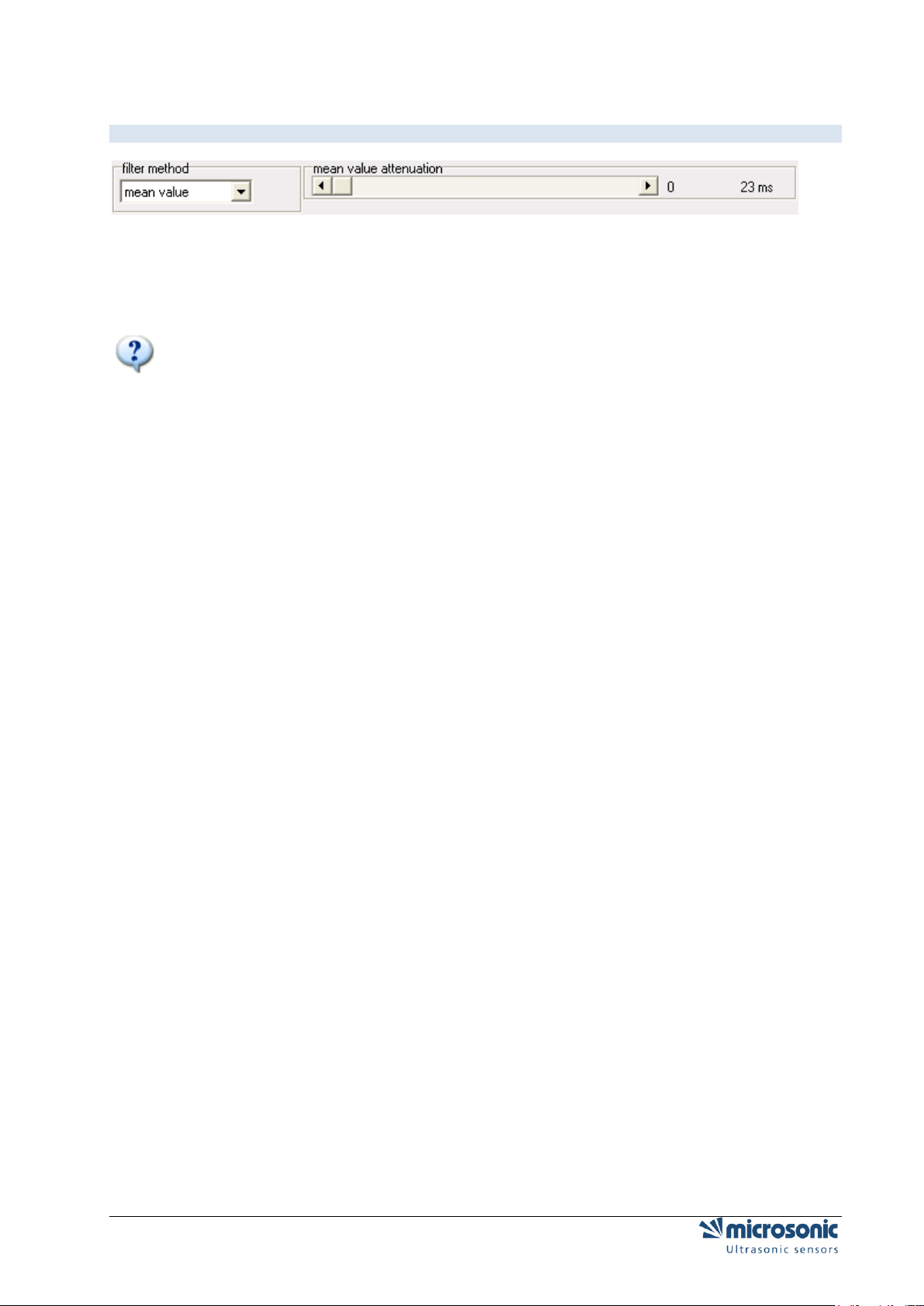
AVERAGE – FILTER
The filter method average simulates an arithmetic mean value calculation over several measurements.
The scroll bar for Attenuation determines how many elapsed measurements shall be taken into account to
form the mean. The resulting settling time for the measurement value to follow a sudden distance jump is
calculated from the time for a single ultrasonic measurement multiplied by the number of measurements,
which are taken into account.
The applied method is not exactly a true mean value calculation from the mathematical point of
view; due to the limited RAM storage capacity of a microcontroller a similar method is employed.
The maximum allowable attenuation should experimentally be derived.
Example
The filter method average is suited especially for analogue sensors in applications, where an attenuation
of the measured distance for both moving directions is needed. Typical applications are coil winding, loop
con-troll and level detection...
On slow processes often the highest filter setting may be chosen. Short term error target, for instance a
fast moving hand through the ultrasonic beam, does hardly affect the output signal.
Page 30 of 51 Changing parameters on distance measuring sensors
Page 31

SENSOR FAMILIES LPC UND UCS
Within these sensor families you are able to select four different types of filter. On every of these filter
types, you can set the filter strength in steps from 0 to 9.
F00 + F01
see:F00 + F01 All Sensor families excepting
F05
= F01 with filter strength P01 + switch-on delay from 1 to 10 s.
F06
This filter works according to the principle of the tolerance belt-filter (see: Tolerance belt - filter
TOLERANCE BELT - FILTER
With this filter a tolerance belt is put symmetrically around the measured value. The current distance
values remain within this belt, they are passed through an average filter.
If the current measured value crosses the tolerance belt (above or below), still the old range-to-target
reading is spent so over the hold time (Attenuation on object withdrawal and/or attenuation on object
approach) be-fore the new value is taken over.
Changing parameters on distance measuring sensors Page 31 of 51
Page 32

PARAMETER CHANGE IN THE DOUBLE SHEET CONTROL
The function of the double sheet detection is to detect two or more sheets lying one on top of the other or
to detect other laminary materials. The sensor system consists of a transmitter and a receiver complete
with integrated evaluation electronics.
A high-frequency ultrasonic transmitter beams from the underside against the sheet material. The emitted
ultrasonic pulse excites the sheet material into vibrations. The effect of these vibrations is for a very small
sonic wave on the other side of the sheet to spread. This wave is received by the ultrasonic receiver
located there. In the case of sheet one on top of the other (double sheet), the receiver detects the
difference in signal and sets its outputs accordingly.
Page 32 of 51 Parameter change in the double sheet control
Page 33

OPERATING MODES
You can select from the following operating modes:
Free-Run-Mode with 3 predifined sensitivity classes and additional teach-in mode, e.g. for
scanning wafers glued with a water film.
Free-Run-Mode with 4 independent teach-in classes.
Trigger-Mode with 2 predefined sensitivity classes and additional teach-in mode
Level or edge triggered mode, e.g. for applications in the imbricated stream.
FREE RUN – 3 PREDIFINED SENSITIVITY CLASSES + 1 TEACH-IN
The dbk+4 operates in the free-run mode ex-works. In the free-run mode, the dbk+4 performs
measurements cyclically.
Should measurements be taken in the imbricated stream, then an external trigger signal can
individually trigger each measurement. To this end, the trigger mode can be parameterized with the aid of
the LCA-2 LinkControl adapter available as an accessory and the LinkControl software.
FREE RUN – 4 TEACH-IN
If the dbk+4 is parameterized in Free-Run mode, you can teach up to 4 different materials.
The sensitivity classes "Standard", "Thick", "Thin" und "Teach-in" can be customized..
With the appropriate buttons the teached classes of materials can be brought back to the default.
Parameter change in the double sheet control Page 33 of 51
Page 34

TRIGGER MODE – 2 VORDEFINIERTE MATERIALKLASSEN + 1 TEACH-IN
If the dbk+4 is parameterized in Trigger mode, you have to contact the external trigger signal to input C2.
In trigger mode the following sensitivity classes are available : »Standard«, »Thin« and »teach-in-value«.
Page 34 of 51 Parameter change in the double sheet control
Page 35

OUTPUT FUNCTIONS
You can make the following settings:
Function for switched output D1
missing sheet (NCC) = single sheet (NOC)
missing sheet (NOC) = single sheet (NCC)
overcontrol (NCC)
overcontrol (NOC)
Function for switched output D2
double sheet (NCC)
doppelbogen (NOC)
MEASURING VALUE WRITER
With the button "Standard", "Dick," "thin" and "Teach-in-value" starts the measuring value writer. The dbk
+4 then temporarily works with these settings.
Parameter change in the double sheet control Page 35 of 51
Page 36

Logical state
Voltage level
pnp
npn 0 -UB
+ UB
1
+ UB
- UB
VOLTAGE LEVEL OF THE LOGIC STATES AT THE CONTROL INPUTS
MOUNTING DISTANCE
Numeric input of the spacing between transmitter and receiver.
SENSITIVITY CLASSES
The fact that the dbk+4 control inputs are unconnected or on logic 0 points to pre-selection of the
"Standard" sensitivity class where the range of sheet material weights from a typical 50 g/m2 up to 800
g/m2 can be scanned.
The 3 control inputs allow the sensitivity classes to be pre-selected in keeping with the Fig 4 table.
The "Thin" setting is to be selected for extremely thin materials, such as bible printing paper, with
weight per unit areas of under 50 g/m2.
The "Thick" setting is available for sheet metals, thick plastic films, paperboard and finest
corrugated card..
Changes between sensitivity classes can be undertaken under on-going operations.
Pre-selecting an over-low sensitivity class can result - even with a single sheet - in a double sheet
signal appearing. In such an instance, the next-higher sensitivity class is to be pre-selected.
Pre-selecting an over-high sensitivity class results - given a single sheet - in the double-sheet
detection indicating overcontrol at the LEDs: one LED lights up green and the other green/red
(orange blend). In such an instance, the next-lower sensitivity class is to be pre-selected.
Parameterization of the D1 switched output onto the "Overcontrol" output function achieved with
LinkControl software results in the overcontrol signal being additionally outputted on D1.
Page 36 of 51 Parameter change in the double sheet control
Page 37

PARAMETER CHANGE IN THE LABEL-/SPLICE SENSORS ESP-4
AND ESF-1
Labels are guided through the fork. An ultrasonic transmitter in the lower tine of the fork beams a fast
sequence of pulses through the backing material. The sound pulses cause the backing material to
vibration, so that a greatly attenuated sound save is beamed from the opposite side. The receiver in the
upper tine of the fork receives this sound wave.
The backing material transmits a different signal level from the label. This signal difference is evaluated by
the esf-1. The signal difference between the backing material and the label can be very slight. To ensure
a reliable distinction, the esf-1 must be trained to the label.
Parameter change in the Label-/Splice Sensors esp-4 and esf-1 Page 37 of 51
Page 38

TEACH-IN-METHODS
The esf-1 can reliably detect high-transparency, reflective materials as well as metallised labels and labels
of any colour. The measurement cycle time automatically self-adjusts to the sound power required. For
thin labels and backing materials, the esf-1 can work at its maximum speed, with a response time of < 300
µs.
To be able to detect special labels, for example labels with punches or perforations, there are three
different teach-in methods available.
A) LEARN BOTH BACKING MATERIAL AND LABEL DYNAMICALLY
During the teach-in process, the backing material and its labels are guided through the fork at a constant
speed.
The esf-1 sensor automatically learns the signal level for the labels and for the gaps between the labels.
This is the standard teach-in for labels.
B) SEPARATE TEACH-IN FOR BACKING MATERIAL AND LABELS
The signal level difference for the backing material and labels might be very slight. In order to still scan
labels with very little difference in signals, teach-in for the signal levels is done separately: teach-in is
firstly done for the backing material and then for the label on it. The switching threshold then lies between
these two signal levels.
C) LEARN WEB MATERIAL ONLY
Web material is generally processed from a roll. The splice to be detected is hidden somewhere in the roll.
There is a separate teach-in method available for this purpose, in which only the web material is learned.
The esf-1 detects the level difference at the splice and sets its output.
EASYTEACH
With EasyTeach, you have a simplified Teach-in process that you have to activate once before initial
commissioning.
To use EasyTeach, you have to decide whether the sensor will act as a label or a splice detector.
Once EasyTeach is activated, you can't switch between NCC/NOC any more.
The EasyTeach functionality is available for sensors with lot numbers > 12xxxxx.
Insert the web material into the fork and carry out one of the three standard Teach-in methods or
EasyTeach.
Page 38 of 51 Parameter change in the Label-/Splice Sensors esp-4 and esf-1
Page 39

PARAMETER CHANGE IN THE WEB EDGE SENSOR BKS+
The bks+ ultrasonic web edge sensor is a fork sensor for scanning the edges of sound-impermeable
materials such as foil or paper.
This is why the bks+ is ideally suited for the web control of highly transparent foils, light-sensitive
materials, materials with greatly varying transparency and paper subject to high paper dust loads.
The fork’s lower leg is equipped with an ultrasonic sensor which cyclically emits short sound impulses,
which are detected by the ultrasonic receiver arranged in the upper fork leg. Material immersing into the
fork covers this sound path and thus attenuates the receive signal in dependence of the coverage, which
is evaluated by the internal electronics. An analogue signal is output in dependence of the coverage
degree.
Parameter change in the web edge sensor bks+ Page 39 of 51
Page 40

TEACH-IN-METHODEN
To adjust the zero position of the edge to be controlled, the sensor can be calibrated with two options.
Completely freeing the fork from the web material
push , then completely fill sensor fork and
push .
Or align the web edge inside the fork with the two marks to ensure a 50 % coverage of the sound path,
then push .
Ready.
ANALOG OUTPUT SETTING
The analog output can be adjusted so that it supplies current or voltage. The characteristic can be
selected as rising or falling.
Voltage / Current Increasing: voltage / current increases with higher coverage
Voltage / Current falling: voltage / current drops with higher coverage
SWITCH OUTPUT SETTING
The switched output of the bks+../FIU or bks+../F can be used e.g. for monitoring purposes. He switches
around the (adjustable) center in a (adjustable) window.
Page 40 of 51 Parameter change in the web edge sensor bks+
Page 41

FILTER SETTING
The filter type F can be chosen from 0 to 3. Where is:
0: No Filter
1: Moving average
2: Median filter
The filter strength can be varied for each filter types between 0-9.
OTHER SETTING
LEDS OFF 30 SECONDS FROM LAST KEY PRESS:
If this feature is activated, the LEDs are off 30 seconds after the last key press. This is needed eg for lightsensitive materials.
CHARACTERISTICS LINEARIZATION:
The characteristic is linearized so that it has a straight course within its limits.
TEMPERATURE COMPENSATION:
see Temperature compensation on page 19
TOUCHCONTROL:
see Fehler! Verweisquelle konnte nicht gefunden werden. on page 19
Parameter change in the web edge sensor bks+ Page 41 of 51
Page 42

DOCUMENTATION OF PARAMETERS
THE PARAMETER LIST
Click , to get a list of the adjusted parameters.
This list documents the parameter settings of the sensor. In the upper text field you can make your own
re-marks. In the lower text field all parameters of the sensor are listed. You can print this list inclusive the
re-marks for your documentation.
Your remarks will be saved by saving the parameter into a file.
Page 42 of 51 Documentation of parameters
Page 43

VISUALISATION OF MEASUREMENTS
SELECTING THE MODE
Click
only for mic-.../M30, lcs and lpc:
Please notice that the sensor in conjunction with LinkControl performs ultrasonic measurements only
under the Measurement menu. When the visualisation is invoked no ultrasonic measurements take place
for some seconds. Also the repetition rate is greatly reduced during visualisation mode. You are allowed
to visualise measured distances on an installation or machine under operation using LinkControl only, if
you have made sure that no harmful situation for man and machine may occur when doing so. When in
doubt you have to power down the installation or machine during visualisation with LinkControl.
Before visualising the measured distances the parameters in the input masks has to be identical
to the ones of the connected sensor. Read out the parameters from the connected sensor first.
You can select out of three different modes:
Numeric presentation
Graphic presentation
Measurement writer
Visualisation of measurements Page 43 of 51
Page 44

NUMERIC PRESENTATION
The measuring value is displayed in "mm" and as a bar graph in percent. The selected detection range is
equivalent to 100%.
The LED's are showing the required state of the switching outputs D1 and D2 respectively the analogue
output. To have correct results the values in the input masks has to be identical to the values stored in the
sensor.
Page 44 of 51 Visualisation of measurements
Page 45

GRAPHIC PRESENTATION
The displayed output characteristics correspond to the settings in the input mask.
The position of the vertical line below the target (red wall) changes proportional to the measured distance.
The expected output voltage and the expected output current is calculated on the values as given in the
input mask and showed in the lower part of the window; thus they should match with the actual analogue
signal on the sensor output (within the specified accuracy). To have correct results the values in the input
masks have to be identical to the values stored in the sensor!
The LED's D1 and D2 are showing the required state of the switching output S1 and S2, respectively the
analogue output. To have correct results the values in the input masks have to be identical to the values
stored in the sensor.
Visualisation of measurements Page 45 of 51
Page 46

MEASUREMENT WRITER
Every measuring value is displayed time continuous like an x-t writer.
The expected output voltage and the expected output current are calculated on the values as given in the
input mask; thus they should match with the actual analogue signal on the sensor output (within the
specified ac-curacy). To have correct results the values in the input masks have to be identical to the
values stored in the sensor!
The LED's D1 and D2 are showing the required state of the switching output S1 and S2, respectively the
analogue output. To have correct results the values in the input masks have to be identical to the values
stored in the sensor.
onlymic+.../TC bzw. mic-...M Sensoren ab 2004 und lpc
Unfiltered (red curve) and filtered measured values (green curve) can be represented simultaneously.
Both measured values are to be fading out. If unfiltered and filtered measured values lie above each
other, one can move the red curve of the unfiltered measured values around some pixels.
MINIMUM/MAXIMUM DISPLAY
Minimum and maximum distance is shown as a yellow bar. With the button Delete you can reset these
values.
TRIGGER
After click on you will see aditional settings. The following parameters can be displayed.
Page 46 of 51 Visualisation of measurements
Page 47

MARKINGS
Blindzone, foreground suppression, switching- and hysteresis points (on sensors with switching output)
and window margins (on sensors with analogue output)
If time markings is active, all X measurements a vertical white line displayed in the diagram. It represents
the time between the measurements
.
TRIGGER
In the mode Free Run the measuring values are displayed in an continuous way
In the mode Triggered writing starts, when the distance value exceed a trigger level. The presentation
ends with reaching the right window margin and starts only then, when the above mentioned condition
comes true.
In the mode Single Shot displaying starts, when the values exceed a trigger level. The presentation ends
with reaching the right window margin and starts only then, when you click the button Reset.
ZOOM
The displayed measuring range (0 mm to the selected detection range) can be reduced for better
visualisation.
Select a sector with the mouse cursor (hold the left mouse button and drag). The range will be shown and
after you release the mouse button, the window will be zoomed.
To switch off the zoom, click on the graphic and following message will be displayed.
Visualisation of measurements Page 47 of 51
Page 48

LOG MEASUREMENTS
For logging, the measurements can be saved into a file.
Push the button Protocol.
Select a file name (ending is *.TXT)
Select the maximum period of time for the logging
Select the cycle for logging..
All sensor parameters will be saved into the file, followed by the measurement values.
Page 48 of 51 Visualisation of measurements
Page 49

INDIVIDUAL INPUT MASK
LOCKING INPUT FIELDS
You can create your own input mask by enabling or disabling certain input fields. This is helpful when you
want to send a floppy disc with a special parameter set and the LinkControl software to a third party, but
only letting them adjust for instance the trip points of switching sensors.
To design an individual input mask the LinkControl software offers the feature to lock / unlock each
parameter input field.
Select from the menu File the submenu Lock Inputs
Enter the password snoopy
Select which input field shall be locked or not.
Individual input mask Page 49 of 51
Page 50

THE LINKCOPY FUNCTION
LINKCOPY WITH LCA-2
With the LCA-2 you can copy parameters of a sensor onto a second sensor of same type and same
product line. For that the software LinkControl is not necessary.
For further information see: quick reference guide on the LCA-2.
Page 50 of 51 The LinkCopy function
Page 51

UPDATING LINKCONTROL
Link Control is continuously updated. Please take a look at our website and download the latest
LinkControl software.
You can find the current LinkControl at the following link:
http://www.microsonic.de/en/Download/LinkControl-software.htm
Link Control even offers the possibility to update the default parameter files. This for example is necessary
if microsonic releases new sensors.
Choose “Help | Update”
A dialog shows your version and the version available on the Internet.
Click Next
LinkControl downloads the update to your computer, there it will be unziped and loaded to LinkControl.
Updating LinkControl Page 51 of 51
 Loading...