

Page 1
Operating Instructions
Ultrasonic label ans splice sensor
with 2 switched outputs
esp-4/3CDD/M18 E+S
esp-4/3BEE/M18 E+S
esp-4/M12/3CDD/M18 E+S
esp-4/M12/3BEE/M18 E+S
Functional principle
With a rapid pulse sequence, an
ultrasonic transmitter beams
upwards against the backing
material. The effect of the sound
pulses inducing the backing material
to vibrate is for a markedly
weakened sonic wave to be emitted
on the opposite side. The receiver
receives this sonic wave and analyses
it.
The backing material signal level is
different to that of the label or
splice. And this difference in signal is
analysed by the esp-4. The difference
between backing material and label
and/or between sheeting and splice
can be very slight indeed. To ensure
certainty with the difference, teachin for the esp-4 sensor must firstly
revolver around the signal level for
the backing material/sheeting.
The esp-4 sensors can be used as a
label and splice sensor. The 3 teachin methods permit the esp-4 sensor
to be optimally set for each and
every assignment.
Ultrasonic sensors
Product description
■ Assured detection of labels made
of paper, metal or (transparent)
plastic.
■ Detection of splices of paper web,
plastic web or metal web.
■ Label/splice and web break output
as pnp or npn switched outputs.
■ Scanning of material weights from
<60 g/m2 to >>600 g/m2; sheet
metals and plastic films up to 0,6
mm thickness.
■ 3 Teach-in modes.
■ Synchronisation.
■ Parametrization via LinkControl.
■ Response time of 300 µs until
lable/splice is detected.
■ Transmitter - receiver spacing can
be selected from 20 to 40 mm
Safety tips
■ Read the operating instructions
before start-up.
■ Only qualified personnel are to
undertake connection, mounting
and settings.
■ Not a safety component in
keeping with the EC Machinery
Directive.
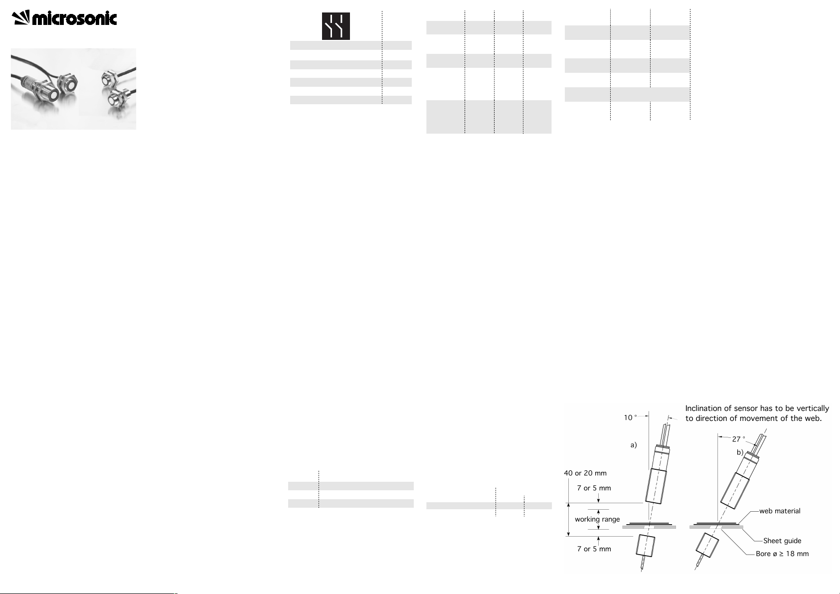
Mounting
▸ Mount transmitter and receiver in
keeping with Fig 1 at the
recommended spacing of 40 mm
± 3 mm (or 20 mm ± 2 mm with
esp-4/M12/...E+S).
esp-4 can be fitted at any position.
▸ Connect the transmitter to the
receiver using the M8 connector.
▸ Connect the receiver 7-strand
control line in keeping with Fig 2.
Fig. 2: Colour coding of the control line
Pointer
■ The coaxiality of transmitter and
receiver must be ≤ 0.5 mm.
■ Transmitter and receiver are not to
be inclined to each other in excess
of 2°.
■ In case of thicker plastic films the
esp-4 is to be mounted at a 27°
inclination to sheet normal (Fig.
1b).
■ Other materials may make a special fitting position necessary. Do
contact microsonic when you
work with these special materials.
■ The max. torque of the nuts is 15
Nm for the M18 and 8 Nm for the
M12 sleeves respectively.
■ The drill hole must be ≥ 12 mm
given that the transmitter is
recess-mounted or a sheet feed is
envisaged between transmitter
and receiver.
■ The line between transmitter and
receiver is not to be bridged with
an external potential.
Start-up
▸ For normal opperation mode leave
all the 3 control inputs
unconnected (see Figs 3 and 4).
▸ Switch on the esp-4 voltage sup-
ply.
Fig. 3: Function of control inputs
+U
B
-U
B
Colour
Brown
Blue
lable/splice output D1
web break output D2
control input C1
control input C2
White
Black
Violet
Pink
control input C3 Grey
Input
C1
C2
Function
Teach-in
Automatic tracking on/off
C3 Synchronization/communication
1) C3 must not be connected to -U
B
Fig. 4: Assignment of control inputs
Teach-in
Teach-in is carried out via contol input C1.
There are 3 Teach-in methods:
■ Dynamic teach-in of backing material and label
■ Separate teach-in for backing material and labels
■ Teach-in only for sheeting
▸ Place the web material between
transmitter and receiver of the
esp-4 and carry out one of the 3
Teach-in methods.
Pointer
■ During Teach-in the control input
C2 has to be left unconnected or
connected to -UB and C3 has to
be unconnected.
Operation
The esp-4 performs measurements
cyclically and depending on the
measurement result it sets the two
switched outputs.
The automatic tracking can be put
on/off during runnig operation.
The conditions of LED 1 and 2 are
shown in Fig. 6.
Fig. 5: Voltage level of the logic states at
the control inputs
Mode
normal
operation
Teach-in
C1 C2
open
or -U
B
See »Te-
ach-in
modes«
open
or -U
B
open
or -U
B
C3
open
1
open
1
automatic
tracking
sychronization
automatic
tracking
and synchronization
open
or -U
B
open
or -U
B
+U
B
open
or -U
B
open
or -U
B
+U
B
open
1
C3 con-
nected
with
each
other
C3 con-
nected
with
each
other
Logical state
0
Voltage level
pnp
-U
B
npn
+U
B
1
+UB-U
B
Fig. 6: LED displays
Factory setting
The esp-4 are delivered with the
following factory settings:
■ Output label/splice output D1 on
NOC.
■ Output D2 on fuction web break.
■ Ouput web break on NOC.
■ 40 or 20 mm spacing.
■ Operation mode on automatic
tracking on/off via input C2.
Automatic tracking
After a Teach-in the esp-4 can track
the working point automatically. In
this way variations in the material to
be scanned and fluctuation in the
ambient temperature can be compensated.
Via control input C2 the automatic
tracking can be put on and off.
Condition
operation
backing
material
LED 1 LED 2
Green
Green
Green
Green
label/splice
web break
Teach-in
Teach-in
dismissed
Red
Green
Green
Red flashing
See »Teach-in methods«
Green Red flashing
Synchronization
If two or more esp-4 shall work close
together they may influence one
another. To avoid this the esp-4 can
be synchronized. To do this all contol
inputs C3 have to be connected with
each other.
Parameterization with
LinkControl
The esp-4 can be extensively
parameterized under LinkControl.
Here you need the optionally
available LinkControl adapter LCA-2
and the LinkControl software for
Windows©.
Operation onto LinkControl
▸ Install the LinkControl software
onto your PC.
Connect the LinkControl adapter
to your PC with the USB cable.
▸ Connect esp-4 to the LCA-2 in
keeping with the Fig 7 table. For
this, use the adapter cable in the
LCA-2 case.
▸ Connect the voltage supply cable
to the LCA-2 on the other side of
the T connector.
▸ Start the LinkControl software and
follow the instructions on the
screen.
Fig. 1: Mounting and installation positions
Page 2
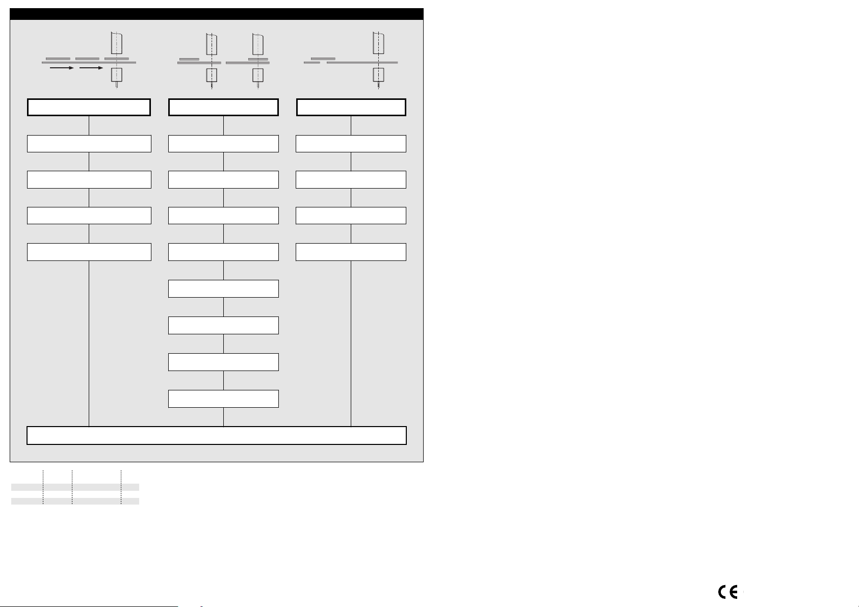
Fig. 7: Connecting dbk+4 to the LCA-2
+UB-U
B
Colour
esp4
Colour
adapter cable
Brown
Blue
Brown
Blue
Pin
1
3
C3/Com Grey Grey 5
Teach-in methods
Teach-in label dynamic
Place backing material with label between transmitter
and receiver.
Teach-in label static
a) Place only backing material between
transmitter and receiver.
Teach-in only for sheeting
(splice sensor)
Place web material between transmitter
and receiver.
Place control input C1 on logic 1 for 3 s until both LED
flash mutualy.
Pull backing material with labels among transmitter
and receiver with constant speed.
both LED flash green
simultaneously
Place control input C1 on logic 1 for 1 s.
one LED flashes green briefly,
one LED is static green
one LED is static green,
one LED flashes green
Place control input C1 on logic 1 for 6 s until
one LED turns off and one LED is on.
Pull only backing material among transmitter
and receiver.
one LED flashes green,
one LED is static green
Place control input C1 on logic 1 for 1 s.
b) Place backing material with label between
transmitter and receiver.
one LED flashes green briefly,
one LED is static green
one LED is static green,
one LED flashes green
Place control input C1 on logic 1 for 9 s until
both LEDs turn off.
Pull web material among transmitter
and receiver.
one LED flashes green briefly,
one LED is static green
Place control input C1 on logic 1 for 1 s.
one LED flashes green briefly,
one LED is static green
one LED is static green,
one LED flashes green
Normal operation
Place control input C1 on logic 1 for 1 s.
Move backing material with label between
transmitter and receiver.
one LED flashes green briefly,
one LED is static red
one LED flashes green,
one LED is static green
Place control input C1 on logic 1 for 1 s.
one LED flashes green briefly,
one LED is static green
one LED flashes green,
one LED is static green
!"
#"
The following settings can be
undertaken:
■ Teach-in of web or label material.
■ Spacing between transmitter and
receiver.
■ NOC/NCC function of the
switched outputs.
■ Function of switched output D2.
some isopropanol onto a cotton
cloth and then wipe the surface
clean. Make sure that the reaction
Also available is a diagrammatic
representation of the readings.
time of the cleaner is kept down.
That means quickly wiping dry the
transducer surfaces.
Maintenance
No maintenance is need on the esp-
4. We would recommend cleaning
the sensor surfaces at the transmitter
and receiver should they become
very dirty. The best thing is to apply
2004/108/EC
Page 3

Technical data
esp-4/3.../M18 E+S esp-4/M12/3.../M18 E+S
Spacing transmitter-receiver
Optimum spacing transmitter-receiver
Blind zone (in front of transmitter and receiver)
Permissible angular deviation
20 to 40 mm
40 mm ± 3 mm
20 to 30 mm
20 mm ± 3 mm
7 mm
10°-27° from the perpendicular of the sheet
5 mm
10°-27° from the perpendicular of the sheet
Ultrasonic frequency
Working range
Operating voltage U
B
400 kHz
web material with grammages of < 20 g/m2 to
500 kHz
web material with grammages of < 20 g/m2 to
>>600 g/m2; paper, metal, plastic
20 V to 30 V DC
>>600 g/m2; paper, metal, plastic
20 V to 30 V DC
Voltage ripple
No-load current consumption
Type of connection
Transmitter-receiver connection
± 10 %
≤ 50 mA
± 10 %
≤ 50 mA
2 m PUR cable, 7 x 0,25 mm
2
At receiver: PUR, 1,2 m;
2 m PUR cable, 7 x 0,25 mm
2
At receiver: PUR, 1,2 m;
Controls
at transmitter: 1 m, PUR; both with M8 connector at transmitter: 1 m, PUR; both with M8 connector
Connection cable to external ultrasonic transducer:
3 Control inputs: C1 to C3
PVC, 1,2 m
3 Control inputs: C1 to C3
Programmable
Response time
Teach-in, LinkControl
300 µs - 2,25 ms, depending on the grammages
Teach-in, LinkControl
300 µs - 2,25 ms, depending on the grammages
Indicator
Housing
Green: working/backing material
Red: label/splice
Green: working/single sheet
Red: double sheet
Red flashing: web break
Brass sleeve, nickel-plated; plastic parts: PBT, PA;
Red flashing: missing sheet
Brass sleeve, nickel-plated; plastic parts: PBT, PA;
Max. tightening torque of nuts
Class of protection to EN 60529
Cable: PUR; ultrasonic transducer:
Polyurethane, epoxy resin with glass content
Cable: PUR/PVC; ultrasonic transducer:
Polyurethane, epoxy resin with glass content
M18: 15 Nm
IP 65
M18: 15 Nm; M12: 8 Nm
IP 65
Operating temperature
Storage temperature
Weight
Norm conformity
+5 °C to +60 °C
-40 °C to +85 °C
+5 °C to +60 °C
-40 °C to +85 °C
130 g
EN 60947-5-2
160 g
EN 60947-5-2
Order no.
Double sheet output
esp-4/3CDD/M18 E+S esp-4/M12/3CDD/M18 E+S
pnp, +UB-2 V, I
max.
= 200 mA, short circuit proof,
switchable NOC/NCC
pnp, +UB-2 V, I
max.
= 200 mA, short circuit proof,
switchable NOC/NCC
Missing sheet output
UE at control inputs C1-C
3
pnp, +UB-2 V, I
max.
= 200 mA, short circuit proof,
switchable NOC/NCC
pnp, +UB-2 V, I
max.
= 200 mA, short circuit proof,
switchable NOC/NCC
> -UB+18 V: logical 1
< -UB+13 V or control input open: logical 0
> -UB+18 V: logical 1
< -UB+13 V or control input open: logical 0
Time delay before availibility
Order no.
Double sheet output
< 300 ms < 300 ms
esp-4/3BEE/M18 E+S
npn, -UB+2 V, I
max.
= 200 mA, short circuit proof,
esp-4/M12/3BEE/M18 E+S
npn, -UB+2 V, I
max.
= 200 mA, short circuit proof,
Missing sheet output
UE at control inputs C1-C
3
switchable NOC/NCC
npn, -UB+2 V, I
max.
= 200 mA, short circuit proof,
switchable NOC/NCC
npn, -UB+2 V, I
max.
= 200 mA, short circuit proof,
switchable NOC/NCC
< -UB+6 V: logical 1
switchable NOC/NCC
< -UB+6 V: logical 1
Time delay before availibility
1)
Can be programmed with LinkControl
> -UB+10 V or control input open: logical 0
< 750 ms
> -UB+10 V or control input open: logical 0
< 750 ms
Brown
White
Black
Violet
Blue
2 pnp switched outputs
U
Pink
Grey
+UB
D2
D1
C1
C2
C3
-UB
Brown
White
Black
Violet
Blue
2 npn switched outputs
U
Pink
Grey
+UB
D2
D1
C1
C2
C3
-UB
MV-DO-108284-290059
microsonic GmbH • Hauert 16 • D-44227 Dortmund • Tel: +49 2 31 / 97 51 51-0 • Fax: +49 2 31 / 97 51 51-51 • E-Mail: info@microsonic.de • www.microsonic.deThe content of this document is subject to technical changes. Specifications in this document are presented in a descriptive way only. They do not warrant any product features.
 Loading...