

Page 1
Operating Instructions
Ultrasonic double sheet detection
with 2 switched outputs
dbk+5/3CDD/M18 E+S
dbk+5/3BEE/M18 E+S
Functional principle
The function of the double sheet detection is to detect two or more
sheets or other laminary materials lying one on top of the other. The sensor system consists of a transmitter
and a receiver complete with integrated evaluation electronics.
A high-frequency ultrasonic transmitter beams from the underside
against the sheet material. The emitted ultrasonic pulse excites the sheet
material into vibrations. The effect of
these vibrations is for a very small
sonic wave on the other side of the
sheet to spread. This wave is received
by the ultrasonic receiver located
there. In the case of sheet one on
top of the other (double sheet), the
receiver detects the difference in signal and sets its outputs accordingly.
Ultrasonic sensors
Product description
■ Assured detection of single, double and multiple sheet.
■ Scanning of sheet material
weights from 100 g/m2 to 2,000
g/m2, corrugated cards, sheet metals, printed circuit boards, films
and plastic sheets up to several
mm thickness possible.
■ Double sheet and missing sheet
output as pnp or npn switched
outputs.
■ Vertical mounting to the sheet running through permitted.
■ Three control inputs allow for an
external setting of sensitivity for
the material to be scanned.
■ Changes to sensitivity classes under ongoing operations can be undertaken.
■ Additional teach-in mode e.g. for
scanning wafers glued with a water film.
■ Optional trigger operation mode
e.g. for applications in the shingled stream.
■ Parameterization via LinkControl
■ 0.5 ms response time until a dou-
ble or missing sheet in the trigger
mode is detected.
■ Transmitter-receiver spacing can
be selected from 30 to 70 mm
Safety tips
■ Read the operating instructions
before start-up.
■ Only qualified personnel are to undertake connection, mounting and
settings.
■ Not a safety component in keeping with the EC Machinery Directive.
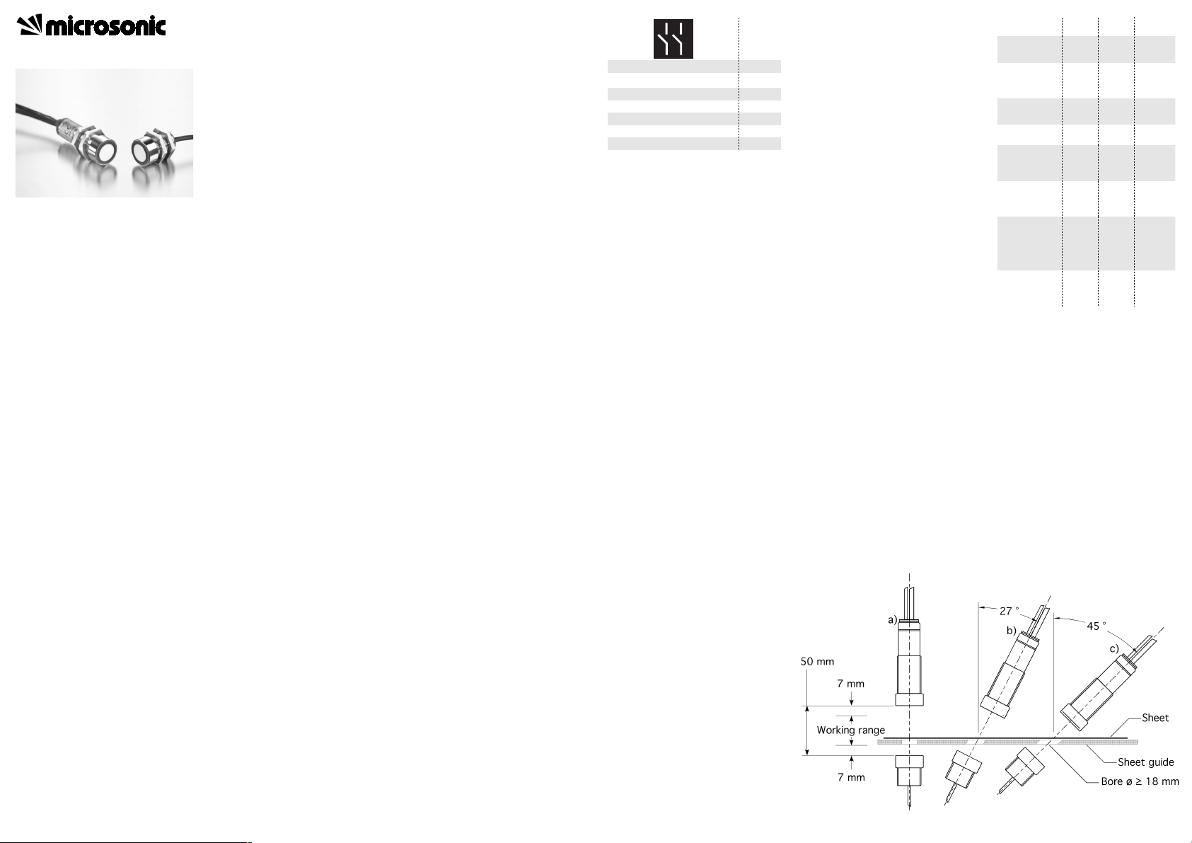
Mounting
▸ Mount transmitter and receiver in
keeping with Fig 1 at the recommended spacing of 50 mm ± 3
mm .
dbk+5 can be fitted at any position .
▸ Connect the transmitter to the re-
ceiver using the M8 connector.
▸ Connect the receiver 7-strand con-
trol line in keeping with Fig 2.
Pointer
■ If required, spacing between trans-
mitter and receiver can be adjusted to the local circumstances in
the 30 to 70 mm range; see under
»Teach-in spacing between transmitter and receiver«.
■ The coaxiality of transmitter and
receiver must be ≤ 0.5 mm.
■ Transmitter and receiver are not to
be inclined to each other in excess
of 2°.
■ Vertical mounting to the sheet is
recommended for papers (Fig 1a).
■ In case of vertical mounting to the
sheet, the spacing between transmitter and/or receiver and the
sheet running through is not to be
under 7 mm.
■ In case of certain sheet metals or
thicker plastic films, the dbk has to
be mounted at an inclination to
sheet normal depending on the
material (Fig. 1b). If necessary the
optimum mounting position has
to be determined in a test.
■ Thick papers and paperboard responsible for faulty switching in
case of vertical mounting can often be scanned at a 27° to 45°
mounting angle to sheet normal.
Corrugated cards have to be measured obliquely to the waves (Fig
1c).
■ Other materials may make a special
fitting position necessary. Do contact microsonic when you work
with these special materials.
■ The max. torque of the nuts is 15
Nm for the M18 sleeves.
■ The drill hole must be ≥ 12 mm
given that the transmitter is recess-mounted or a sheet feed is
envisaged between transmitter
and receiver. The recommendation
is for a 18 mm diameter (see Fig
1).
■ The line between transmitter and
receiver is not to be bridged with
an external potential.
Fig. 2: Colour coding of the control line
Start-up
▸ Select the »Standard« sensitivity
class by placing all the 3 control
inputs onto logic 0 (see Figs 3 and
4) or leave them unconnected.
Switch on the dbk+5 voltage supply.
Pointer
■ The »Standard« sensitivity class
corresponds to the setting of
predecessor model dbk-5.
Check the function with a test sheet.
▸ Hold a single test sheet within the
working range between transmitter and receiver.
The LED must light up green for
"Single sheet detected«. (Should the
LED light up red, then check on the
dbk+5 fitting dimension and the selected test sheet.)
▸ Hold a double test sheet within
the working range between transmitter and receiver.
The LED must light up red for "Double sheet detected«.
▸ Remove all the sheets between
transmitter and receiver.
The LED must flash red for "Missing
sheet detected«.
+U
B
-U
B
Colour
Brown
Blue
Single/missing sheet output
Double sheet output
Control input C1
Control input C2
Black
White
Violet
Pink
Control input C3/Com Grey
Pointer
■ You can use a material of a high
sheet weight as the test sheet or
the test sheet itself obtainable as
an accessory with the »dbk test
sheet« article name. This test
sheet works as critical material at
the ambient temperature in the
»Standard« sensitivity class and
can be used to examine the correct adjustment and function.
Factory setting
The dbk+5 are delivered with the following factory settings:
■ Free-run mode with 3 sensitivity
classes and teach-in
■ Missing sheet output on NCI
■ Double sheet output on NCI
■ 50 mm spacing
Fig. 9: LED displays
Condition
single sheet
single sheet
overmodulation
LED 1 LED 2
Green
Green
Green
Green
+ Red =
Orange
static on
static on
double sheet
missing sheet
Teach-in
activated
Teach-in
dismissed
Red
Red
Red
Red
Green
Red
Green
Red
static on
flashing
flashing
mutually
flashing
mutually
Teach-in spacing transmitter-receiver
Teach-in
dismissed
Red
Red
Green
Red
flashing
mutually
flashing
mutually
Fig. 1: Mounting and installation positions
Page 2
2004/108/EC
Operation in the free-run
mode
The dbk+5 operates in the free-run
mode ex-works. In the free-run
mode, the dbk+5 performs measurements cyclically.
Pointer
■ If measurements should be taken
in the shingled stream, then an external trigger signal can individually trigger each measurement. To
this end, the trigger mode can be
parameterized with the help of
the LCA-2 LinkControl adapter
available as an accessory and the
LinkControl software.
Fig. 3: Voltage level of the logic states at
the control inputs
Sensitivity classes
The fact that the dbk+5 control inputs are unconnected or on logic 0
points to pre-selection of the »Standard« sensitivity class where the
range of sheet material weights from
a typical 100 g/m2 up to 2,000 g/m
2
can be scanned.
■ The 3 control inputs allow the sensitivity classes to be pre-selected in
keeping with the Fig 4 table.
■ The »Thin« setting has to be selected for thin materials.
■ The working range can be enlarged to thicker materials by
choosing the setting »Thick«.
■ Changes between sensitivity
classes can be undertaken under
on-going operations.
■ Pre-selecting an over-low sensitivity class can result – even with a
single sheet – in a double sheet
signal appearing. In such an instance, the next-higher sensitivity
class is to be pre-selected.
■ Pre-selecting an over-high sensitivity class results – given a single
sheet – in the double-sheet detection indicating overmodulation at
the LEDs: one LED lights up green
and the other green-red (orange
Logical state
0
Voltage level
pnp
-U
B
npn
+U
B
1
+UB-U
B
blend). In such an instance, the
next-lower sensitivity class is to be
pre-selected.
Pointer
Parameterization of the D1 switched
output onto the »Overmodulation«
output function achieved with LinkControl software results in the overmodulation signal being additionally
outputted on D1.
Teach-in
The teach-in mode is also available
for materials glued to each other
across their full extent (e.g. two wafers bonded with a water film, a
spline on a paper web) and special
materials which cannot be scanned
with one of the 3 sensitivity classes
▸ Select the teach-in mode (C1 and
C2 on logic 1) in keeping with the
table in Fig 4.
This is the way to teach-in a material:
▸ Place a single sheet of the material
in the working range of the double sheet detection.
▸ Place the C3 control input on logic
1 for a minimum of 3 seconds.
Materials with inhomogeneities
must be moved during the teachin phase so that dbk+5 can detect
them.
Success with a teach-in operation is
shown by a green LED. In instances
of where no material teach-in was
possible, dbk+5 flashes in red. Then
repeat the operation.
▸ On finishing the teach-in opera-
tion, either place the C3 control
input on logic 0 or leave it unconnected.
The material can now be scanned.
Pointer
■ C3 must not be on logic 1 when
the supply voltage is connected.
Fig. 4: Free-run mode: selection of the sen-
sitivity class and Teach-in
Parameterization with LinkControl
The dbk+5 can be extensively parameterized under LinkControl. Here
you need the optionally available
LinkControl adapter LCA-2 and the
LinkControl software for Windows©.
Operation onto LinkControl
▸ Install the LinkControl software
onto your PC.
Connect the LinkControl adapter
to your PC with the USB cable.
▸ Connect dbk+5 to the LCA-2 in
keeping with the Fig 5 table. For
this, use the adapter cable in the
LCA-2 case.
▸ Connect the voltage supply cable
to the LCA-2 on the other side of
the T connector.
▸ Start the LinkControl software and
follow the instructions on the
screen.
Fig. 5: Connecting dbk+5 to the LCA-2
The following settings can be undertaken:
■ Numeric input of the spacing between transmitter and receiver
■ Function for the D1 switched output
Missing sheet = NCC (single sheet
= NCO) or
Missing sheet = NCO (single sheet
= NCC) or
Overmodulation = NCC or
Overmodulation = NOC
Standard
Thick
C1 C2
000
1
C3
0
0
Thin
Teach-in-Mode
Teach-in active
110
1
1 1
0
0
1
+UB-U
B
Colour
dbk+5
Colour
adapter cable
Brown
Blue
Brown
Blue
Pin
1
3
C3/Com Grey Grey 5
■ Function for the D2 switched output
Double sheet = NCI or
Double sheet = NCO
■ Operating mode
Free-run mode with 3 pre-defined
sensitivity classes and additional
teach-in mode or
Free-run mode with 4 independent teach-in classes or
Trigger mode with 2 pre-defined
sensitivity classes and additional
teach-in mode or
Edge- or level-controlled trigger
mode
Also available is a diagrammatic representation of the readings.
Operation in the trigger
mode
If LinkControl was used to parameters the trigger mode, then the external trigger signal is to be placed on
the C2 control input.
Available in the trigger mode are
sensitivity classes »Standard«, »Thin«
and the teach-in mode in keeping
with the Fig 6 table.
In the edge-controlled trigger setting
(see Fig 7), the double sheet detection takes a measurement with every
edge from 0 to 1. The finding is then
stored until the next trigger edge.
Fig. 6: Trigger mode: selection of the sensi-
tivity class and teach-in mode
In the level-controlled trigger mode,
dbk+5 keeps on taking measurements for as long as the trigger signal is on hand. With dbk+5 deactivated (C2 control input to logic 0),
the reading of the last measurement
at the switched outputs is frozen (see
Fig 8).
Free-run mode with 4 independent teach-in classes
Parameterization with the aid of
LinkControl of the free-run mode
with 4 independent teach-in classes
makes teach-in possible for up to 4
different materials. As a result, the
»Standard«, »Thick«, »Thin« and
»Teach-in mode« sensitivity classes
can be individually adjusted (see online help in LinkControl).
Teach-in spacing between
transmitter and receiver
Teach-in of the selected spacing between transmitter and receiver must
be undertaken should you not have
mounted transmitter and receiver at
the recommended 40 mm or 30 mm
spacing.
▸ Clear the measuring section of
sheet materials between transmit-
Standard
Thick
C1 C2
00Trigger
Trigger
C3
0
1
Teach-in-Mode
Teach-in active11
Trigger
Trigger01
ter and receiver.
Place all the 3 control inputs on
logic 1.
Switch on the supply voltage: The
LEDs flash alternately red and
green.
Wait at least 2 seconds.
Place the C3 control input on logic
0.
Pointer
■ Any failure to teach-in the set
spacing results in dbk+5 flashing
in red for 3 seconds.
dbk+5 is operating normally. Finally,
select the requested type of operation through the control inputs.
Maintenance
No maintenance is need on the double sheet detection. We would recommend cleaning the sensor surfaces at the transmitter and receiver
should they become very dirty. The
best thing is to apply some isopropanol onto a cotton cloth and then
wipe the surface clean. Make sure
that the reaction time of the cleaner
is kept down. That means quickly
wiping dry the transducer surfaces.
Double sheet Missing sheetSingle sheet
Assingnment
1
0
t
1
0
t
1
0
t
Control input C2
Double sheet output
Missing sheet output
Double sheet Missing sheetSingle sheet
Assingnment
1
0
t
1
0
t
1
0
t
Control input C2
Double sheet output
Missing sheet output
Fig.7: Trigger mode edge-controlled Fig. 8: Trigger-mode level-controlled
Page 3

Te ch n ic a l d at a
dbk+5/3CDD/M18 E+S dbk+5/3BEE/M18 E+S
Spacing transmitter-receiver
Optimum spacing transmitter-receiver
Blind zone (in front of transmitter and receiver)
Permissible angular deviation
30 to 70 mm
50 mm ± 3 mm
30 to 70 mm
50 mm ± 3 mm
7 mm
±45° from the perpendicular of the sheet
7 mm
±45° from the perpendicular of the sheet
Ultrasonic frequency
Working range
200 kHz
papers with grammages of 100 g/m2 to
200 kHz
papers with grammages of 100 g/m2 to
2,000 g/m2; metal-laminated sheets and films
up to 5 mm thickness, self-adhesive films, sheet
2,000 g/m2; metal-laminated sheets and films
up to 5 mm thickness, self-adhesive films, sheet
Operating voltage U
B
Voltage r ip ple
metals up to 2 mm thickness, corrugated
cardboard, wafer, printed circuit boards
metals up to 2 mm thickness, corrugated
cardboard, wafer, printed circuit boards
20 V to 30 V DC
± 10 %
20 V to 30 V DC
± 10 %
No-load current consumption
Ty pe of co n ne c ti o n
Tra ns mi tt er -r ec ei ve r con ne ct io n
≤ 50 mA
2 m PUR cable, 7 x 0,25 mm
2
≤ 50 mA
2 m PUR cable, 7 x 0,25 mm
2
At receiver: PUR, 1,2 m;
at transmitter: 1 m, PUR; both with 3-pin M8 plug
At receiver: PUR, 1,2 m;
at transmitter: 1 m, PUR; both with 3-pin M8 plug
Controls
Programmable
3 Control inputs: C1 to C3
Selection of sensitivity classes, Teach-in, LinkControl
3 Control inputs: C1 to C3
Selection of sensitivity classes, Teach-in, LinkControl
< 500 µs
5,5 ms
< 500 µs
5,5 ms
Release delay Trigger-Mode
Indicator
Until next edge
5,5 ms
Until next edge
5,5 ms
Green: working/single sheet
Red: double sheet
Green: working/single sheet
Red: double sheet
Housing
Red flashing: missing sheet
Brass sleeve, nickel-plated; plastic parts: PBT, PA;
Red flashing: missing sheet
Brass sleeve, nickel-plated; plastic parts: PBT, PA;
Cable: PUR; ultrasonic transducer:
Polyurethane, epoxy resin with glass content
Cable: PUR; ultrasonic transducer:
Polyurethane, epoxy resin with glass content
Max. tightening torque of nuts
Class of protection to EN 60529
Operating temperature
Storage temperature
15 Nm
IP 65
15 Nm
IP 65
+5 °C to +60 °C
-40 °C to +85 °C
+5 °C to +60 °C
-40 °C to +85 °C
Weight
Norm conformity
Order no.
150 g
EN 60947-5-2
150 g
EN 60947-5-2
dbk+5/3CDD/M18 E+S dbk+5/3BEE/M18 E+S
Double sheet output
Missing sheet output
pnp, +UB-2 V, I
max.
= 200 mA, short circuit proof,
switchable NCO/NCI
npn, -UB+2 V, I
max.
= 200 mA, short circuit proof,
switchable NCO/NCI
pnp, +UB-2 V, I
max.
= 200 mA, short circuit proof,
switchable NCO/NCI
npn, -UB+2 V, I
max.
= 200 mA, short circuit proof,
switchable NCO/NCI
UE at control inputs C1-C
3
Time delay before availibility
Pin assignment
> -UB+18 V: logical 1
< -UB+13 V or control input open: logical 0
< -UB+6 V: logical 1
> -UB+10 V or control input open: logical 0
< 300 ms < 750 ms
1)
Can be programmed with LinkControl
Brown
White
Black
Violet
Blue
U
Pink
Grey
+UB
Missing sheet
Double sheet
C1
C2
C3
-UB
Brown
White
Black
Violet
Blue
U
Pink
Grey
+UB
Missing sheet
Double sheet
C1
C2
C3
-UB
MV-DO-108329-324993
microsonic GmbH • Hauert 16 • D-44227 Dortmund • Tel: +49 2 31 / 97 51 51-0 • Fax: +49 2 31 / 97 51 51-51 • E-Mail: info@microsonic.de • www.microsonic.deThe content of this document is subject to technical changes. Specifications in this document are presented in a descriptive way only. They do not warrant any product features.
 Loading...