

Page 1
Sensor adjustment with Teach-in procedure
2-point adjustment
Completely free the fork from
the web material.
Press push-button for ca. 3 s,
until the green LED and +LED
flash
simultaneously.
Wait for 2 s.
Cover the sound path com-
pletely with web material.
1-point adjustment
Align the web edge inside the
fork with the mark to obtain a
50 % coverage of the sound
path.
Press push-button for ca. 6 s,
until the green LED and -LED
flash
simultaneously.
Set analogue output
Lock push-button
Turn supply voltage OFF.
While pressing the push-button
turn supply voltage ON.
Press push-button for ca. 13 s,
until the +LED and -LED flash
simultaneously.
green LED:
The function of
the analogue
output is
displayed:
flashes
+LED on, -LED off:
0-10 V, rising
+LED on, -LED off:
0-10 V, falling
+LED off, -LED on:
4-20 mA, rising
+LED off, -LED off:
4-20 mA, falling
Keep push-button pressed for
ca. 3 s, until green LED and +
LED simultaneously flash
quickly.
green LED:
-LED:
+LED:
flashes
off
on: push-button
active
off: push-button
locked
Factory setting
Turn supply voltage OFF.
While pressing the push-button
turn supply voltage ON.
Keep push-button press for
ca. 13 s, until the green LED
flashes quickly.
Press push-button for ca. 1 s,
until green LED flashes and +
LED is off.
Normal mode operation
To change output function
press push-button for ca. 1 s.
Wait for 10 s.
Normal mode operation
To change setting press
push-button for ca. 1 s.
Wait for 10 s.
operating voltage U
B
housing
≤ 60 mA
LEDs yellow: deviation from center/switching window
weight
time delay before availability
190 g
< 300 ms
bks+3/FIU
Push-Pull, UB-4V, -UB+2 V, I
max
= 100 mA
1
5
2
34
1 Push-Pull switched output and analogue output
+U
B
-U
B
Sync/Com
1
2
4
5
3
U
R
L
F
I/U
Ultrasonic Sensors
Further settings
Operating Instructions
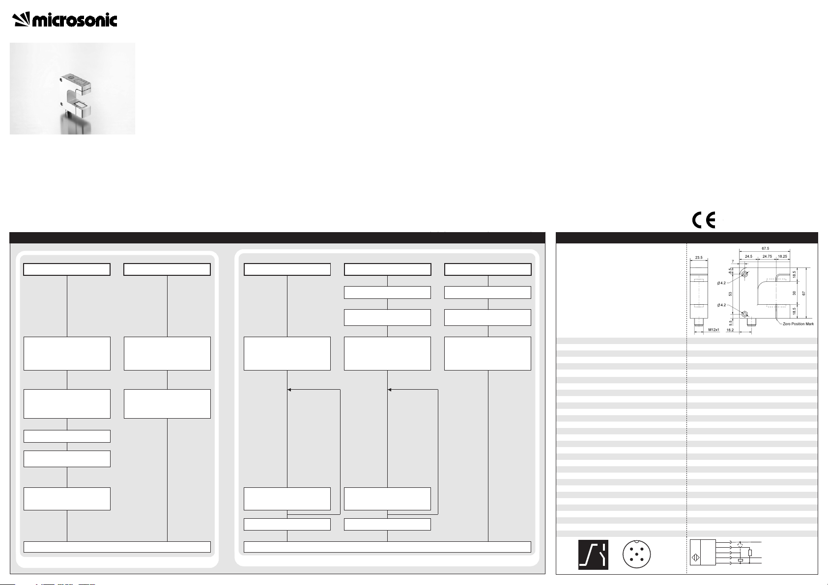
bks+3/FIU
Ultrasonic web edge sensor with
analogue output and
IO-Link interface
Product Description
The bks+ ultrasonic web edge sensor
is a fork sensor for scanning the
edges of sound-impermeable
materials such as foil or paper.
The fork’s lower leg is equipped with
an ultrasonic sensor which cyclically
emits short sound impulses, which
are detected by the ultrasonic
receiver accommodated in the upper
fork leg. Material immersing into the
fork covers this sound path and thus
attenuates the receive signal, which
is evaluated by the internal
electronics. An analogue signal is
output in dependence of the
coverage degree.
Using the LinkControl-Adapter LCA2 and LinkControl software, the
switched output can be programmed
in window mode around the zero
position.
The bks+ sensors are IO-Link-capable
in accordance with IO-Link specification V1.1.
Via the Teach-in button on the
edge sensor’s top, the sensor can
be adjusted to the material to be
controlled.
Choosing between rising and
falling output characteristic is
possible.
Three LEDs indicate the position
of the web material inside the
fork.
Safety Notes
Read the operating instructions
prior to start-up.
Connection, installation and ad-
justment works may only be carried out by expert personnel.
No safety component in ac-
cordance with the EU Machine
Directive.
Installation
Mount the sensor at the installa-
tion site.
Connect a connection cable to
the M12 device plug.
For optimum measurement re-
sults the sensor should be mounted thermally conductive.
Start-Up
Connect the power supply.
Carry out the adjustment in ac-
cordance with the diagram.
Synchronisation
If two or more edge sensors are
mounted in a distance < 400 mm
the internal synchronisation should
be used. Connect Sync-channels (Pin
5 at the units receptacle
sors
.
) of all sen-
Factory setting
Analogue output on voltage out-
put.
Rising analogue characteristic (0
V at maximum coverage).
Switched output on NCC.
Switched output window is ± 1,5
mm around zero position
.
Maintenance
microsonic sensors are maintenancefree. With heavy dirt deposits, we recommend a cleaning of the white
sensor surface.
Note
For optimum measurement re-
sults the material to be detected
should be kept in a range of ± 5
Technical data
mm around the centre between
the upper and lower fork leg.
Using the LinkControl-Adapter
LCA-2 (optional accessory) and
the LinkControl-Software V7.6
all Teach-in- and additional sensor parameter settings may be
made.
Depending on the function the
ultrasonic transducers in the upper and lower fork leg are
mounted with a slope of 2°.
2004/108/EWG
Adjust sensor to web edge
fork width 30 mm
fork depth
operating range
transducer frequency
no-load current consumption
class of protection to EN 60 529
operating temperature
resolution
voltage ripple
type of connection
controls
indicators
programmable
synchronisation
storage temperature
response time
repetition rate
order no.
analogue output
switched output
43 mm
min. 12 mm (± 6 mm)
170 kHz
< 0.005 mm
20 to 30 V DC, reverse polarity protection
± 10 %
zinc die cast lacquered, plastic parts: PBT
ultrasonic transducer : polyurethane foam,
epoxy resin with glass contents
IP 65
5-pin M12 initiator plug,
brass, nickel-plated
Teach-in-button
LED green: center or within switching window
LCA-2 with LinkControl
internal synchronisation up to 10 sensors
+5°C to +60°C
-40°C to +85°C
4.5 ms
4 ms
current output 4-20 mA, voltage output 0-10 V
voltage output 0-10 V
short-circuit-proof, switchable rising/falling
switchable NOC/NCC; short-circuit-proof
Page 2
microsonic GmbH | Hauert 16 | 44227 Dortmund | Germany | Tel: +49 2 31 / 97 51 51-0 | Fax: +49 2 31 / 97 51 51-51 | E-Mail: info@microsonic.de | www.microsonic.de The content of this document is subject to technical changes. Specifications in this document are presented in a descriptive way only. They do not warrant any product features.
MV-DO-131221-392368
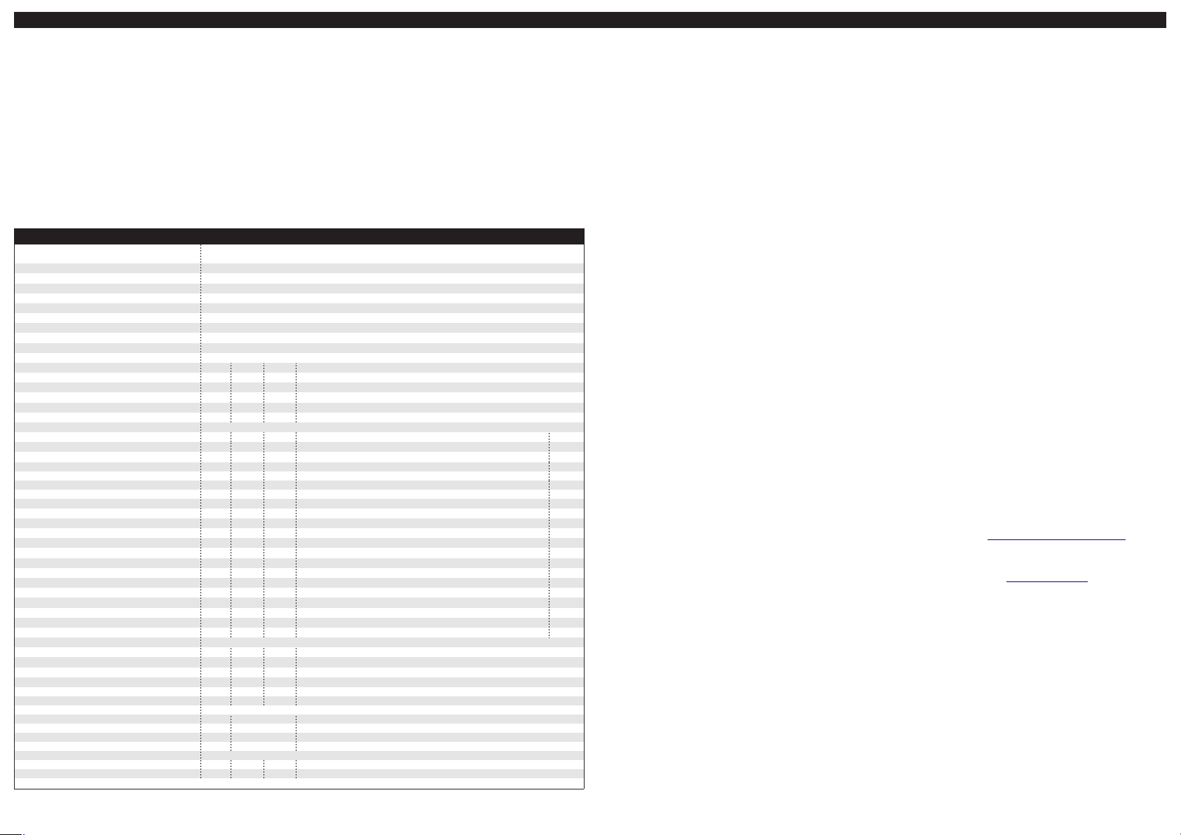
IO-Link Mode
IO-Link Data
physical layer
bks+3/FIU
IO-Link revision
compatibilty
block parameter
data storage
V1.1
V1.0.1
yes
yes
SIO mode support
min cycle time
baud rate
format of process data
yes
4 ms
COM 2 (38,400 Bd)
16 Bit, R, UNI16
content of process data
service data IO-Link specific
vendor name
Bit 0-15: degree of coverage with 0.003 mm resolution
index
0x10
vendor text
product name
product ID
product text
0x11
0x12
0x13
0x14
service data sensor specific
Teach-in via push-button
linearisation of the output characteristic
index
format
0x40
0x41
UINT8
UINT8
temperature compensation
normalisation of the measurement value
analogue output mode
rising/falling output characteristic curve
0x42
0x43
UINT8
UINT8
0x44
0x45
UINT8
UINT8
NCC/NOC
synchronisation via pin 5
automatic turning-off LEDs
repetition rate
0x46
0x47
UINT8
UINT8
0x48
0x49
UINT8
UINT8
transmission length
outer margin of analogue characteristic
inner margin of analogue characteristic
measurement filter
0x4A
0x4B
UINT8
UINT16
0x4C
0x4D
UINT16
UINT8
filter strength
center of switching window
width of switching window
on-delay
0x4E
0x4F
UINT8
UINT16
0x50
0x51
UINT16
UINT8
off-delay
LED display
system commands
0x52
0x53
UINT8
UINT8
index
restore IO-Link parameter
sensor adjustment: fork cleared
sensor adjustment: fork 50 % covered
sensor adjustment: fork 100 % covered
0x02
0x02
0x02
0x02
reset to factory setting
events
0x02
code
0x8ca0
typ
Notification
observe
0x8ca1
0x8ca2
Notification
Notification
index
format
measurement value
1)
Distance values are expressed as multiples of the internal resolution of about 0.003 mm.
0x54
UINT16
accessRvalue
microsonic GmbH
RRwww.microsonic.de
bks+
RRbks+3/FIU
Ultraschall-Sensor
access range
R/W
R/W
0: activated; 1: deactivated
0: deactivated; 1: activated
default
0
1
R/W
R/W
0: deactivated; 1: activated
Diagnostic parameter, must not be changed!
R/W
R/W
0: output deactivated; 2: current output, 3 : voltage output
0: rising characteristic curve; 1 : falling characteristic curve
1
1
3
1
R/W
R/W
0: NOC; 1 : NCC
0: deactivated; 1: activated
R/W
R/W
0: deactivated; 1: activated
8-80 (2-20 ms)
1
1
1
16
R/W
R/W
System parameter, must not be changed!
0-4095
1)
R/W
R/W
0-4095
1)
0-2: F00-F02
71
4095
0
0
R/W
R/W
0-9: P00-P09
0-4095
1)
R/W
R/W
0-4095
1)
0-200 (0-200 ms)
0
2047
1023
0
R/W
R/W
0-200 (0-200 ms)
0: state of the output; 1: middle position
access value
0
0
WW130
161
WW162
163
W 164
name
parameter was changed
sensor adjustment successful
sensor adjustment failed
access range
R 0-4095
The bks+ sensors are IO-Link-capable
in accordance with IO-Link specification V1.1 and compatible to V1.0.1.
Pointer
In IO-Link mode LinkControl is not
available.
Process data
The bks+ cyclically transmits the
value corresponding to the measured
coverage degree with a resolution of
0.003 mm.
Service data
The following sensor parameters
may be set via IO-Link.
Teach-in via push-button
The push-button can be activated/
deactivated for sensor settings with
Teach-in.
Linearisation of the output characteristic
To increase the absolute accuracy in
the edge areas, the linearisation of
the output characteristic can be disabled.
Temperature compensation
The temperature compensation is
used for measurement value correction for varying ambient temperatures and can be disabled.
Normalisation of the measurement value
This parameter is used for diagnostic
purposes and may not be changed
during normal operation.
Analogue output mode
For the analogue output either the
function output voltage or current
output can be selected.
Rising / falling analogue characteristic
The analogue characteristic can be
set on rising (0 V / 4 mA at full coverage) or falling characteristic.
Set NOC/NCC
The NCC or NOC output function can
be present for the switched output.
Synchronisation
As in SIO mode up to 10 sensors can
be synchronised by interconnecting
the sync-channel (pin 5) of each sensor. The synchronisation can be disabled.
Switching off the LEDs
When activated, the LEDs are switched off 30 seconds after a key
press. After a new key press they will
run for 30 seconds. This automatic
shutdown can be deactivated.
Repetition rate
The repetition rate can be adjusted in
the range 2-20 ms.
Note
At 2 ms repetition rate the IO-Link
communication is made every second cycle time.
Transmission length
This system parameter must not be
changed.
Window margins analogue characteristic
The window margins of the analogue characteristic can be adjusted
over the entire operating range of
the sensor.
Note
The inner window margin has to be
lower then the outer window margin.
Measurement filter
bks+ ultrasonic sensors provide for a
choice of 3 filter settings:
F00 (no filter)
Each ultrasonic measurement acts
on the output in an unfiltered
manner.
F01 (average value filter)
Forms approximately the arithmetic
mean of several measurements.
According to the mean value the
output is set. The number of measurements, from which the mean is
formed is dependent on the chosen filter strength.
F02 (median filter)
Finds the median of several measurements. According to the median
the output is set. The number of
measurements, for which the median is determined is dependent on
the selected filter strength.
Filter strength
For each measurement value filter, a
filter strength between 0 (weak filter
effect) and 9 (strong filter effect) can
be selected.
Switching window
If the web edge is within the switching window the switching output
is set. The switching window is defined by the adjusted center and the
width.
Note
The switching window has to be
completely within the operating range.
On-delay
With activated on-delay, the switching output is set when the web
edge is for the adjusted time within
the switching window.
Off-delay
With activated off-delay, the switching output is reset when the web
edge is for the adjusted time outside
the switching window.
LED display
It can be selected whether the LED
display indicates the position of the
web edge in the switching window or
within the range of ± 8 % around the
center of the operating range.
System commands
With 5 system commands the following settings may be carried out:
restore IO-Link parameter
sensor adjustment: fork cleared.
sensor adjustment: fork 50 % co-
vered
sensor adjustment: fork 100 %
covered
Reset to factory settings.
Events
The bks+ sensor sends the following
events:
parameter was changed
sensor adjustment successful
sensor adjustment failed
IODD file
The latest IODD file you will find
on
the internet under
www.microsonic.de/en/IODD
.
For further informations on IO-Link
see www.io-link.com.
 Loading...