

Page 1

1
OPERATOR’S MANUAL
MICRO SEVEN, Inc.
MODEL CD15
CALLER-ID RECEIVER
Micro Seven, Inc.
P.O. Box 5597
Beaverton, OR
97006
U.S.A.
phone: 503-693-6982
fax: 503-693-9742
http://www.microseveninc.com
e-mail: [email protected]
Page 2

2
Copyright, 2003 by Micro Seven, Inc. All right reserved.
Contents of this publication may not be reproduced in any form without the written
permission of Micro Seven, Inc.
All requests for repairs should be directed to the factory.
There will be no warranty when the instrument is misused, or when the factory seal on the
instrument is broken.
Printed in U.S.A.
Specification and price change privileges are reserved.
Page 3

3
CONTENTS
SECTION 1 INTRODUCTION
SECTION 2 SPECIFICATIONS
SECTION 3 OPERATIONS
3.1 AC/DC Adapter and External DC Input Operations
3.2 Front-panel Description
3.3 Rear-Panel Description
3.4 First-time operation and Initialization Procedure
3.5 CD15 Control Register
3.5.1 Bellcore/ETS standard, CD15 Control Register bit 2 position of bit 7-0.
3.5.2 No control character modes, CD15 Control Register bit 1 position of bit 7-0
3.5.3 Telephone number only format, CD15 Control Register bit 0 position of bit 7-0
3.5.4 How to read and write CD15 Control Register
3.5.5 Input signal attenuation CD15 Control Register bit 4
3.5.6 OFF-HOOK CONTROL, CD15 CONTROL REGISTER BIT 3, OHTIMEREG, and WAITREG
3.6 CD15 Interface Register
3.6.1 Hardware handshake (RTS and CTS)
3.6.2 No hardware handshake method
3.6.3 Character echo method from PC
3.6.4 Time delay between RS232C transmit
3.6.5 How to set up CD15 Interface Register
SECTION 4 FCC RULES, PART 15
Page 4

4
INTRODUCTION
Micro Seven model CD15, caller-ID receiver receives caller-ID FSK signals on telephone lines,
and converts to ASCII signals for outputs at RS232C interface to PC. It provides decoding of
caller-ID signals for both Bellcore (American) and ETS (European) standards that are
associated with ring signals. ASCII data output for RS232C interface may be selected among
raw data, control-character-stripped format, or telephone number format. The telephonenumber format outputs telephone numbers only. Many RS232C data transfer handshake
methods are provided including hardware handshake (RTS/CTS), software handshake
(XON/XOFF) or no handshake modes. Standard accessories include AC/DC power adapter,
RS232C interface cable, and operator’s manual. Communication error is displayed If there is
a checksum error.
Micro Seven, Inc. provides product warranty that is listed in specification section. Micro
Seven assumes no liability for loss of property, money, or human lives by application of CD15,
caller-ID receivers.
Page 5

5
SECTION 2
SPECIFICATIONS
Input signal requirement:
Input sensitivity: -13 dBm nominal, -23 dBm minimum
Ringer equivalency number: REN=1
Caller-ID compatibility:
Caller-ID on-hook delivery associated with ring signal
ETS-standard: CD15 Control Register-bit 2 off
Bellcore standard: CD15 Control Register-bit 2 on
RS232C interface: 9-pin D-sub connector
Baud-rate: 1200
Stop bit: 1
Data bit: 8
Handshake: RTS/CTS (hardware), XON/XOFF, or no handshake which is selected by
programming of CD15 Interface Register.
Front-panel indicators:
1. Caller-ID Data Received LED (red color), to indicate that caller-ID data is available.
2. Ring Signal (red color), to indicate that ring signal is received.
3. Power Indicator, to indicate that power is connected to CD15.
Communication errors with incorrect checksum: a word "ERROR" is output at RS232C port at
the end of caller-ID data.
Line characteristics:
Input impedance for caller-ID FSK signals: 1k ohm +/- 5%
Line Input Jacks: USOC-RJ11-C, standard modular phone jacks, J1 for Telephone line and J2
for telephone set
Power Switch: on when the switch is pushed in, off when the switch is pushed out.
AC/DC Adapter: 117VAC +/- 5%, or 230VAC +/- 5%(for optional 230V AC/DC Adapter)
DC input: 12VDC unregulated, 800mA maximum
Power Indicator: green LED display
Dimensions: 19 cm (4") W x 4.5 cm (1.75") H x 10 cm (7.5") L
Weight: 400g (0.8 lbs.)
Page 6

6
Environmental: Operating temperature: 0 to 35 degree C, Humidity: 85% RH at 35 degree C
Warranty/Service: 6 months limited warranty. No warranty if any factory seal is broken.
Service is performed at the factory, usually within 5 working days.
Micro Seven assumes no liability for loss of property, money, or human lives by application of
CD15, caller-ID receivers.
Standard accessories:
117 V or 230V input AC/DC Adapter (117V input unit is a standard.), 9-pin M-F D-sub cable,
and operator's manual
Country of Origin: Manufactured in United States of America
Page 7

7
SECTION 3
OPERATION
3.1 AC/DC Adapter and External DC Input Operations
The CD15 is operated with AC/DC Adapter or external DC source. The standard AC/DC
Adapter for CD15 inputs 117V-AC power. The 230V version of AC/DC Adapter is available as
an option.
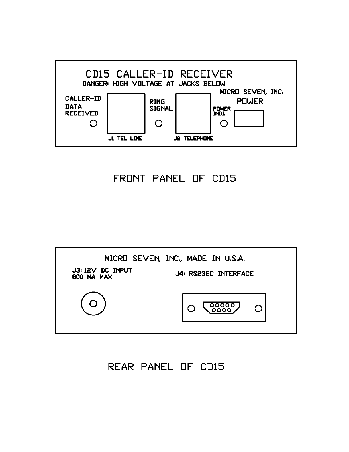
3.2 Front-panel Description
The front panel of CD15 is shown below.
1. J1 (RJ11-C): Line 1 Input Jack for connection to telephone line
2. CALLER-ID DATA RECEIVED to indicate that CD15 has received caller-ID data, and it is
available at the RS232C interface.
3. J2 (RJ11-C): Line 2 Input Jack for connection to telephone sets
4. RING SIGNAL Indicator to indicate it receives ring signal.
5. Power ON (when the switch is in.) or OFF (when the switch is out).
6. Power LED: on when the power is on.
3.3 Rear-Panel Description
The rear panel of LS15-C is shown below.
1. J3: DC Input to connect AC/DC Adapter.
2. J4: RS232C interface, attach the interface cable attached.
Page 8
8
Page 9

9
3.4 First-time operation and Initialization Procedure
Connect AC/DC power adapter to rear panel connector. Connect 9-pin RS232C cable that
is provided with CD15. Turn on the power switch of CD15.
In Window-type PC, go to Hyperterminal modes. And select as follows:
Select 1200 baud, one stop bit, and no parity. Select direct connection to com1, 2, 3, or 4
whatever RS232C port is assigned to. Select hardware handshake. Select VT100 mode.
Initialize CD15 Control and Interface Registers as follows:
The recommending commands for ETS mode, raw-data, and hardware handshake are:
M4B00
M3D00
Then, connect a telephone line cable to either one of telephone connectors on the front
panel of CD15. Using a telephone set on another telephone line to call a number that is
assigned to the telephone line that is connected to CD15. Ring Signal Indicator on the front
panel of CD15 is flashing. And when the Ring Signal Indicator is turned off, the Caller-ID Data
LED is turned on momentarily to indicate that CD15 has received caller-ID data. The PCscreen would display date/time, telephone numbers, and names depending on type of
caller-ID formats. If there is communication problem on the telephone line and CD15 did not
receive the correct checksum in caller-ID data, a word "ERROR" is displayed at the end of
caller-ID data.
The description of CD15 Control and Interface registers are as follows:
3.5 CD15 Control Register
The CD15 Control Register, one byte long, is read or written by a special command string
over RS232C interface. The CD15 Control Register is a non-volatile memory, and it only needs
to be written once. It provides selection of caller-ID standards and ASCII output formats for
PC.
3.5.1 Bellcore/ETS standard, CD15 Control Register bit 2 position of bit 7-0.
When the bit 2 of CD15 control register is on, Bellcore (North American standard) is selected.
When it is off, ETS (European standards) is selected. Major differences between Bellcore and
ETS standards are frequency shift frequencies. Bellcore standards are 1200 Hz for mark signal
and 2200 Hz for space signal, and ETS standards are 1300 Hz for mark signal and 2100 Hz for
space signal.
3.5.2 No control character modes, CD15 Control Register bit 1 position of bit 7-0
When the bit 1 of CD15 is on, all the non-visible characters such as control characters are
replaced with a carriage return (ASCII 13 decimal) and line feed (ASCII 10 decimal).
3.5.3 Telephone number only format, CD15 Control Register bit 0 position of bit 7-0
Page 10

10
When the bit 0 of CD15 is on, telephone numbers are output at RS232C interface.
3.5.4 How to read and write CD15 Control Register
The CD15 Control Register is written by the following command:
M4B(n1)(n2), where n1 and n2 forms a 8-bit bytes. When it is written, CD15 sends "C" to signal
that it has been written into the non-volatile memory.
For example, for the Bellcore format and raw data format with control characters, the
written command is M4B04. When ETS standard and raw data format is required, the written
command is M4B00.
The CD15 Control Register is read by the following command:
R4B
3.5.5 Input signal attenuation CD15 Control Register bit 4
It is recommended to attenuate caller-ID signal by setting CD15 Control Register bit4 for
general operation. For weak caller-ID signal, CD15 Control Register bit 4 may be set.
3.5.6 OFF-HOOK CONTROL, CD15 CONTROL REGISTER BIT 3, OHTIMEREG, and WAITREG
When the bit 3 of CD15 control register is on, off-hook relay is turned on to establish off-hook
state to answer incoming ring signal. The duration of the off-hook relay is determined by
programming OHTIMEREG as follows:
M54(n1)(n2) where n1 n2 forms two digits hexadecimal number with increment of 100 ms. For
example, M541D would programs three seconds period.
The above sequence of turning on relay is delayed by WAITREG as follows:
M53(n1)(n2) where n1 n2 forms two digit hexadecimal number with increment of 100 ms. For
example M530A would programs one second delay.
The recommended programming sequence is as follows:
M4B18
M530A
M541D
3.6 CD15 Interface Register
CD15 Interface Register also resides in CD15, and it provides selection of RS232C interface
handshake method. Software handshake using XON and XOFF is enabled all the time. The
written command is M3D(n1)(n2), and read command is R3D. A character "C" is output
when write operation into CD15 non-volatile memory is complete.
3.6.1 Hardware handshake (RTS and CTS)
When all bits in CD15 Interface Register are off, hardware handshake method is selected.
The written command is M3D00. It sends "C" after writing into non-volatile memory.
3.6.2 No hardware handshake method
Page 11

11
When bit 3 among bit 7-0 is on, hardware handshake using RTS/CTS is disabled. The written
command is M3D18 to select non-hardware handshake mode and character echo method.
3.6.3 Character echo method from PC
When bit 4 of CD15 interface register is on, character (13 decimal) input to CD15 is required
to transmit a next character from CD15 to PC.
3.6.4 Time delay between RS232C transmit
When bit 5 of CD15 interface register is on, 5 millisecond time delay is provided between
transmission of characters.
3.6.5 How to set up CD15 Interface Register
The CD15 Interface Register is also a non-volatile memory inside CD15, and it may be set by
the following command:
M3D(n1)(n2), where n1 and n2 forms a 8-bit bytes.
When all bits in CD15 Interface Register needs to be cleared to select hardware handshake,
send M3D00. If hardware handshake method is disabled and character echoing is enabled,
send M3D18.
Page 12

12
SECTION 4
FCC RULES, PART-15
Warning
This equipment generates, uses, and can radiate
radio frequency energy, and if not installed and
used in accordance with the instruction manual,
may cause interference to radio communications.
It has been tested and found to comply with the
limits for a Class A computing device pursuant to
Sub-part J of Part 15 of FCC Rules, which are
designed to provide reasonable protection
against such interference when operated in a
commercial environment. Operation of this
equipment in a residential area is likely to cause
interference, in which cases the user at his own
expense will be required to take whatever
measures may be required to correct the
interference.
 Loading...