

Page 1
V1.0
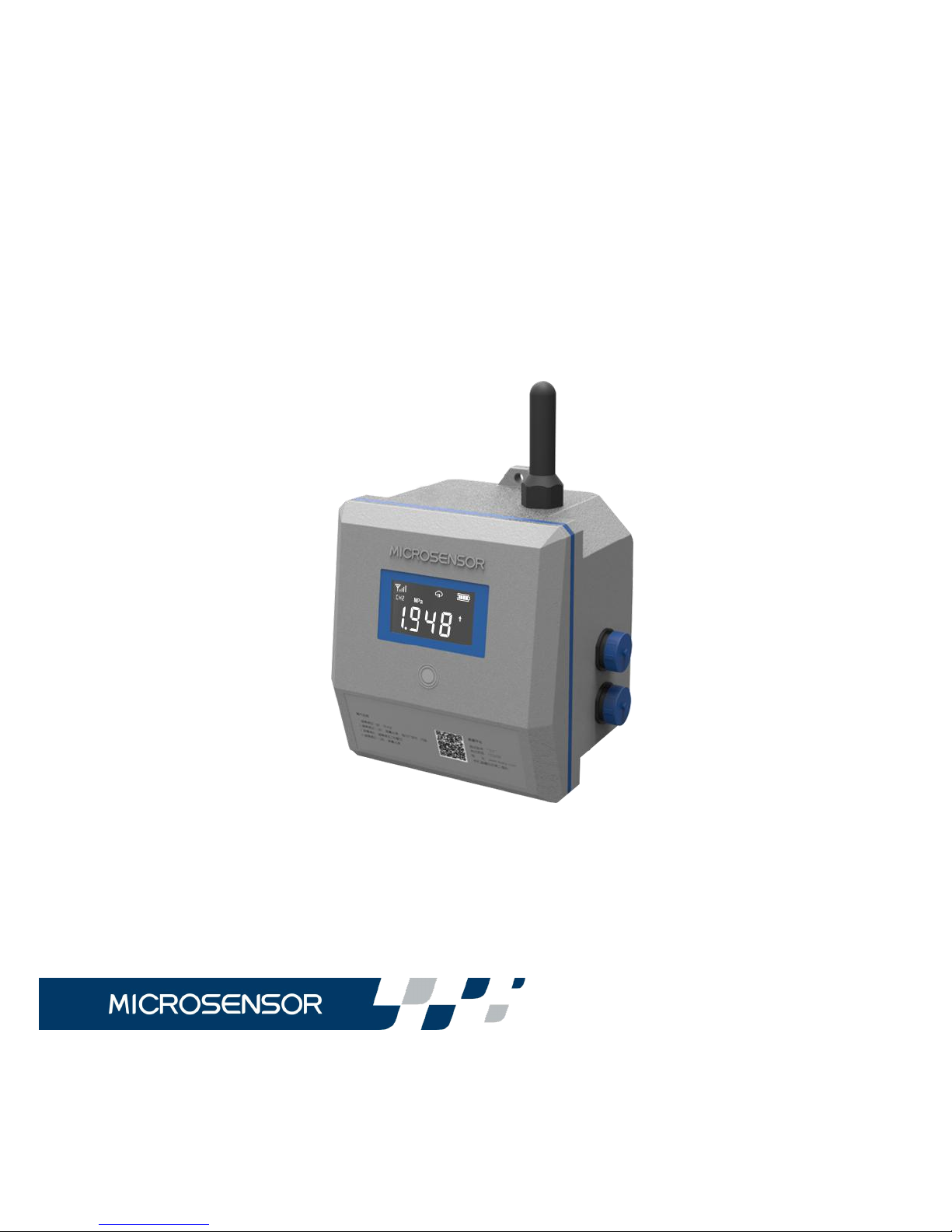
Earth1006
Operation Manual
Page 2

I
CONTENTS
1 Introduction..........................................................................................................1
1.1 Brief introduction.....................................................................................1
1.2 Features....................................................................................................1
1.3 Basic parameters....................................................................................2
1.4 Outline dimension(Unit: mm)............................................................... 4
1.5 Panel structure........................................................................................4
1.6 Display...................................................................................................... 5
1.7 Key instruction.........................................................................................5
1.8 Interface....................................................................................................5
1.9 Application topology...............................................................................6
1.10 Unpacking..............................................................................................7
1.11 Boot operation.......................................................................................7
2 Detailed parameters..........................................................................................8
2.1 Power supply........................................................................................... 8
2.2 Display instruction.................................................................................. 9
2.3 Network mode....................................................................................... 11
2.4 Interface definition................................................................................12
2.4.1 Power interface......................................................................... 12
2.4.2 AI interface................................................................................. 14
2.4.3 DI/PI interface............................................................................ 15
2.4.4 RS485 communication interface........................................... 16
2.4.5 Camera interface...................................................................... 19
Page 3

II
3 Device configurations..................................................................................... 19
3.1 configuration tool..................................................................................19
3.2 Local configuration method................................................................20
3.3 Remote configuration method........................................................... 21
3.4 Configuration options.......................................................................... 21
4 Installation instruction.....................................................................................29
4.1 Installation tool......................................................................................29
4.2 Installation method, dimension and instruction............................. 29
4.2.1 Installation method................................................................... 29
4.2.2 Installation instruction.............................................................. 29
4.2.3 Installation dimension.............................................................. 30
4.3 SIM card installation............................................................................ 30
4.4 Device battery replacement...............................................................32
4.5 Fixture.....................................................................................................33
4.5.1 Underground installation examples...................................... 33
4.5.2 wall-mounting type....................................................................35
4.5.3 hoop-mounting type................................................................. 36
4.5.4 solar mounting type..................................................................37
5 Data platform instruction................................................................................38
6 FAQ.....................................................................................................................38
7 Responsibility................................................................................................... 41
Page 4

III
Our company keeps the product technology and craftwork’s modification
rights. If the information were changed, no more notice would be edited.
Please pay attention to the latest introduction.
Our company keeps the final power of interpretation for this operation
menu.
Page 5

1
Thank you for choosing the products from Micro Sensor Co., Ltd.
To better use this product, please read this operation manual
carefully before using.
1 Introduction
1.1 Brief introduction
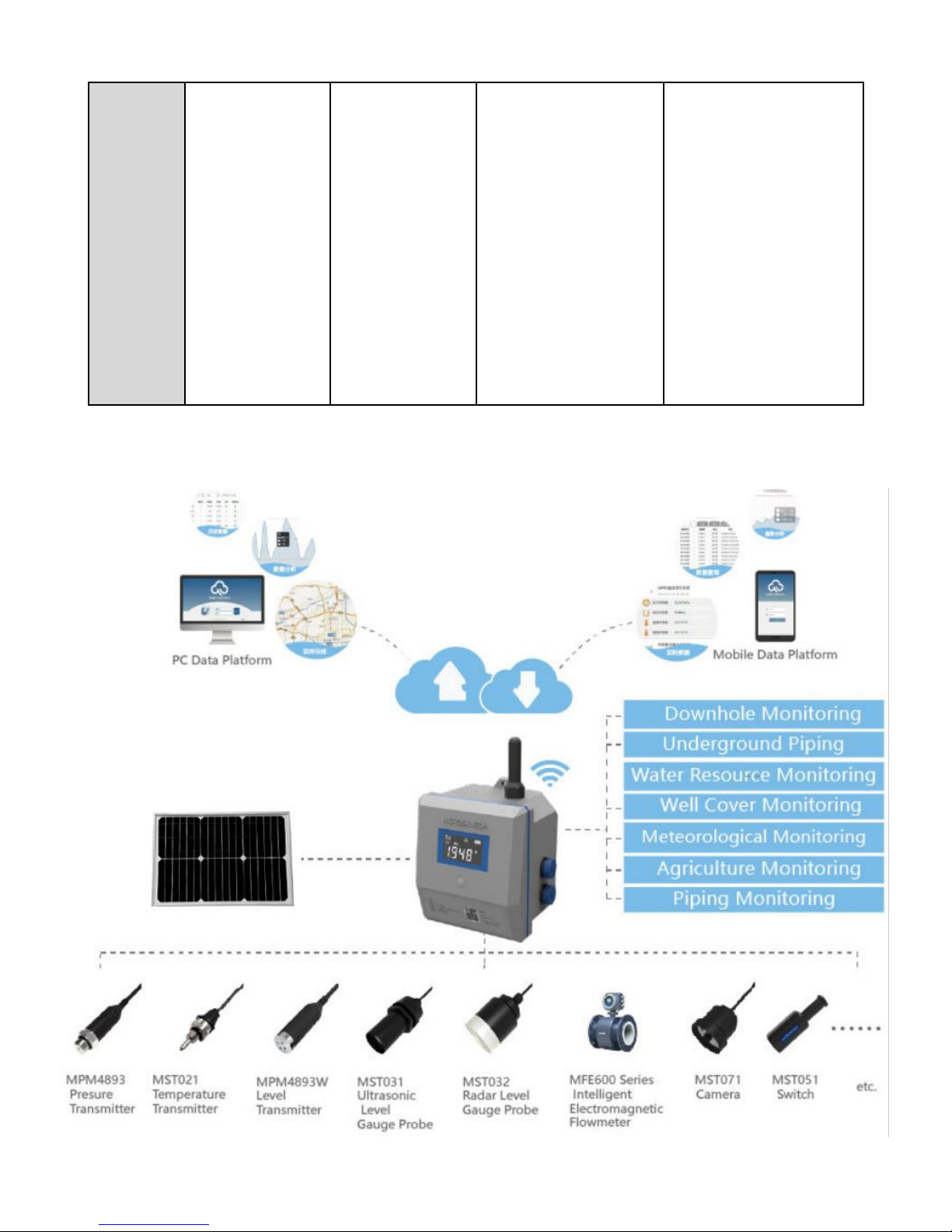
Earth1006 Remote Monitoring Terminal is a compact device with battery
supply, ultra-low power consumption, IP68 protection, wireless
communication and various sensor data collection function, in specific
circumstance, multiple power supply options are available. It is suitable
for the monitoring fields without power supply condition and the harsh
environment. It could realize the multi-function including data collection,
storage, alarming and transmission for underground water, firefighting
water, dam water, water supply and drainage pipeline.
With a wide coverage of wireless network, the product could detect the
real-time data of many monitoring sites in a wide range of areas like
tap-water pipeline pressure, flow, underground water, agricultural
irrigation, dam level, water monitoring, wind, rain, ambient temperature
and humidity, air quality monitoring, water flow monitoring, image and
firefighting pipeline monitoring, especially suitable for Underground Well
detection application in a harsh environment.
1.2 Features
•IP68 protection--dust-proof and water-proof
•Variety of power supply optional and with ultra-low power
Page 6

2
consumption
•Integrated battery with 3~5 years’ lifespan
•Wireless transmission, no field wiring
•Multi-parameter including pressure, temperature, level, flow, image
and manhole cover motoring
•Multi-channel with max. 8-way sensor access
•Remote configuration for collection, transmission and image
interval
•Remote configuration for upper and lower alarm limit and web
real-time warning
•PC and mobile terminal data application
•Support customer self-built system and configuration application
•Equipped with installation accessories
•Solution for underground pipe-network and pipe rack
1.3 Basic parameters
Power supply
Mode: battery/solar power/12~28V DC/110~240V AC
Consumption: sleeping current ≤[email protected]
Transmission average current ≤[email protected]
Interface
Interface type: 3-way AI, 2-way DI/PI,1-way RS485,1-way Camera
Data transmission
Communication mode: 2G/Multi-Bands/NB-Iota/LoRa
Page 7

3
Wake-up mode: magnetic activation/timing/alarm wake-up
Sampling interval: 1,5,10,30,60,360,720,1440 minutes optional,
alarms are given at the intervals, and maximum 3 times warning can
be sent over each interval to ensure longer battery life.
Transmission interval: 1,5,10,30,60,360,720,1440 minutes optional
Image interval: 30,60,720,1440 minutes optional
Upload information: sensor data, battery information, network status,
self-check information
Data storage
Local storage: Flash 4MB (more than 200,000 history data)
Configuration
Configuration mode: local/remote configuration
Display
Segment LCD, with backlight
Environmental condition
Working temperature: -20℃~70℃
Storage temperature: -40℃~85℃
Others
Protection: IP68 (work normally for 72 hours at 1m below the water)
Housing material: PA6+30%GF
Installation method: wall-mounting, hoop-mounting
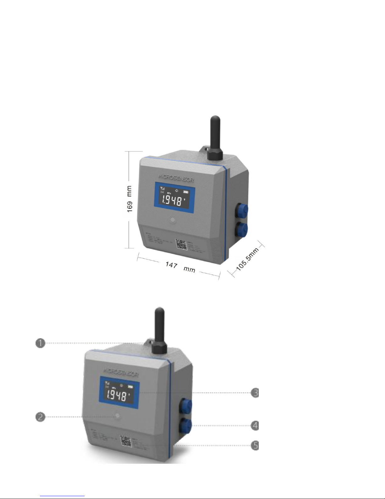
Outline dimension: 147×262.5×105.5mm
Page 8
4
Weight: about 2.3kg
Accessory: magnetic bar*1, fixed support*1, M5 bolt*1, ф8mm
expansion bolt*3, ф200mm hoop *2
1.4 Outline dimension(Unit: mm)
1.5 Panel structure
Note:
1-mounting hole
2-magnetic control key
3-display screen
4-fool-proof interface
5-operation instruction
Page 9
5
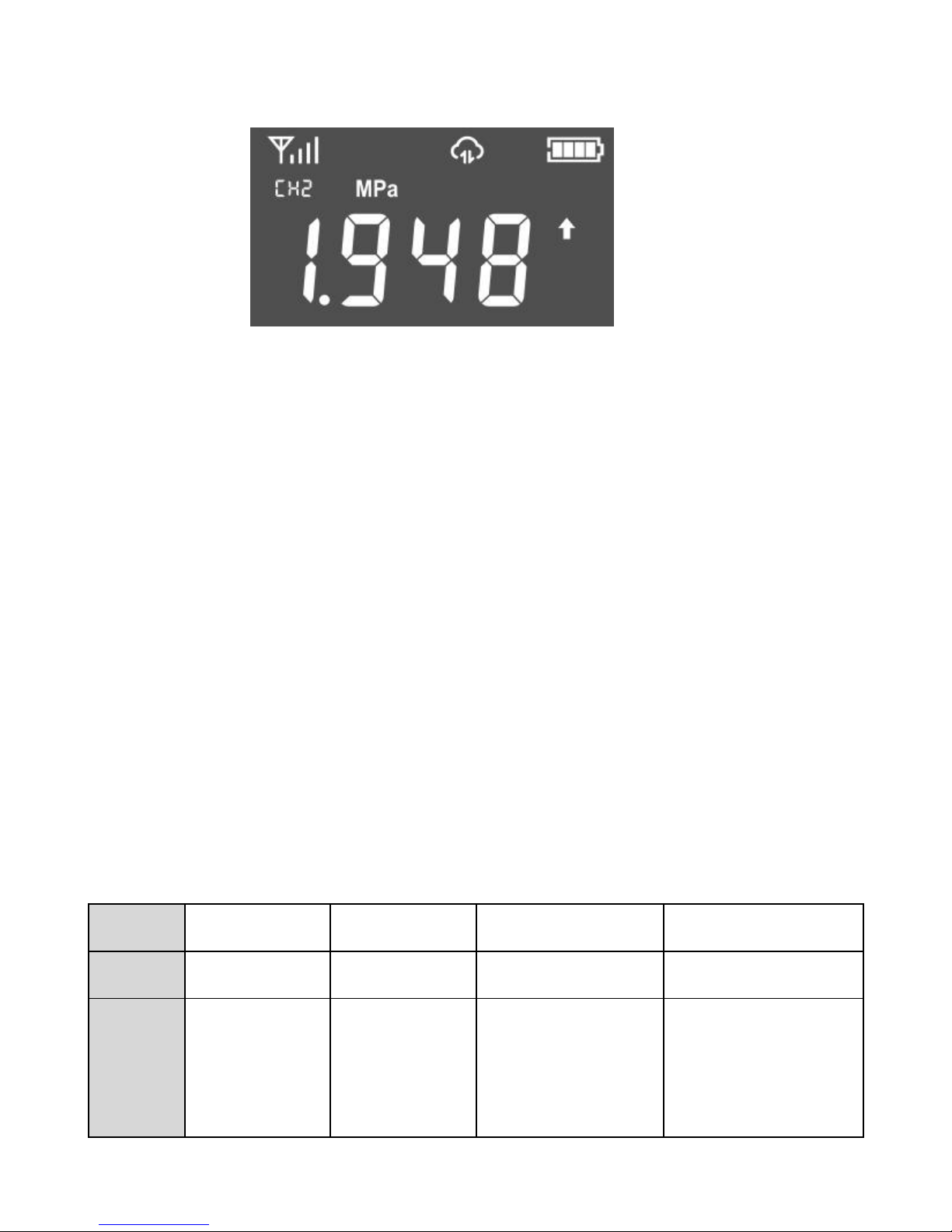
1.6 Display
1.7 Key instruction
Keys need to use the matching magnetic bar to operate, when the
magnetic bar close to or gently click the magnetic control key, Earth1006
Remote Monitoring Terminal will come into the key operation.
Off state (key induces 1s and the screen is not lit), key induces 8s, the
device boot;
Boot state, the key induces 1s, the screen lit;
When the screen is bright, the key induces 1s flip;
When the screen is bright, the key induces 8s off.
1.8 Interface
Table 1.1 Device interface
TypeAIDI/PI
RS485
Camera
Qty.3211
Signal
0V~5V DC/
4mA~20mA
DC
Switch/pulse
ModBus RTU
Pictures only, video
transmission not
available
┄ Device status
┄ Channel NO./unit
┄ Channel value/alarm
Page 10
6
Remark
Collection
accuracy
±0.5%FS
Input current
≤30mA
Low level
0V~1V DC
High level
5V~12V DC
Pulse
frequency
≤10Hz
Support
max.3-way
sensor parameter
analysis and also
be used for device
configuration
RS485
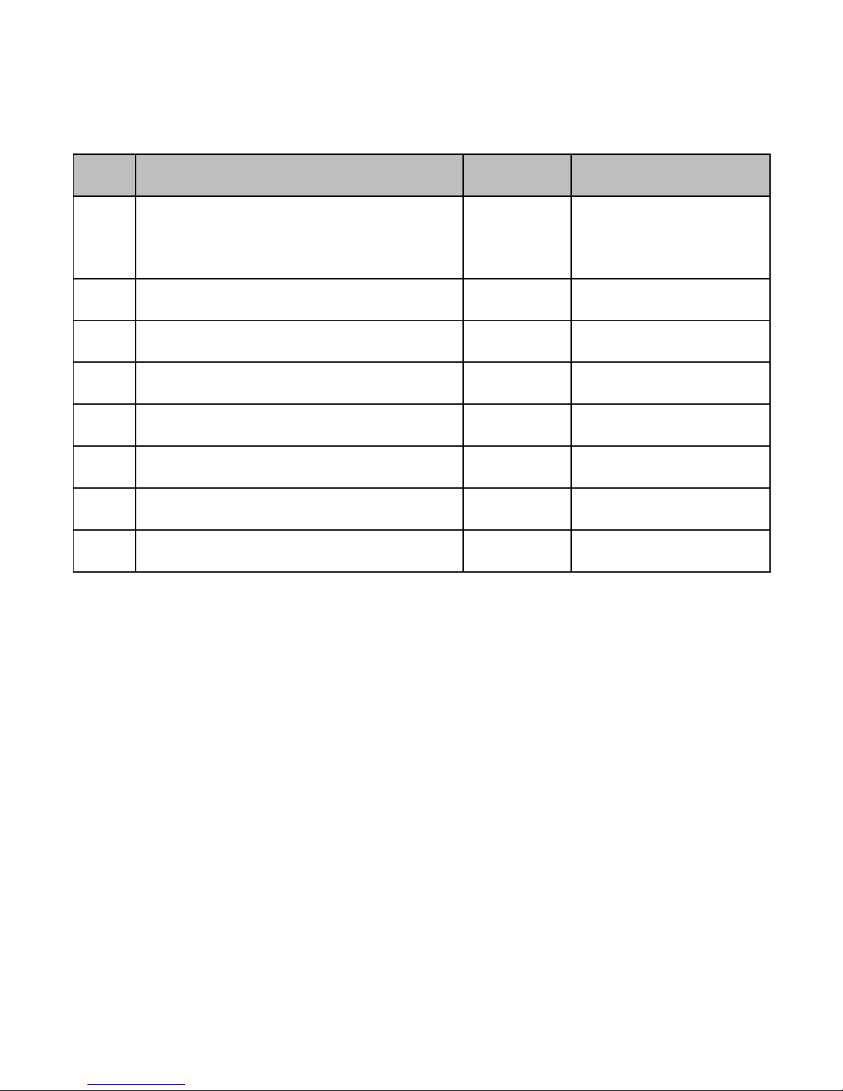
1.9 Application topology
Page 11
7
1.10 Unpacking
Table 1.2 packing list
No.
Item
Qty.
Remark
1
Earth1006 Remote Monitoring
Terminal
1 set
2
Magnetic bar
1pc
3
Hanging bracket
1set
Including fixed bolt
4
Expansion screw
3pairs
Wall mounted
5
Stainless steel hoop
2pcs
Stud mounted
6
Configuration line
1pc
1pc for each batch
7
Operation manual
1pc
8
Certification
1pc
After unpacking, please check carefully according to above list. The
specific quantity shall be consistent with the customer order contract. If
there is damage, loss, shortage or discrepancies of accessories, please
contact the manufacturer in time.
1.11 Boot operation
After receiving the product, please connect different interface sensor,
with more than 8s magnet induction magnetic control buttons, powered
on, the screen lit, entered the work flow, subsequent parameters
configuration can be remote, as shown in the device configuration.
Page 12

8
2 Detailed parameters
2.1 Power supply
The power parameters are shown in table 2.1.
Table 2.1 power parameters
Power Supply
Non-rechargea
ble Battery
Rechargea
ble Battery
DC
Power
AC
Power/12VDC
Adapter
Solar
Power
Battery
Capacity
(See description
on label
/Nameplate)
20Ah/12V
12VDC
110V~240V
AC
50/60Hz
20 Ah/12V
Solar Panel:
12V/20W
Battery
Lifetime
3~5 years
(Related to
transmission
frequency)
Longer than
1
month(Relat
ed to
transmission
frequency)
\
\
More than 1
month
(Related to
Transmissio
n
frequency )
Feed
100mA/14.4V
DC
100mA
/12VDC
100mA
/12V DC
100mA
/12V DC
100mA
/12V DC
Power
Consumption
Sleep Current ≤30uA/14.4V
Transmission Average Current ≤50mA/14.4V
Page 13
9
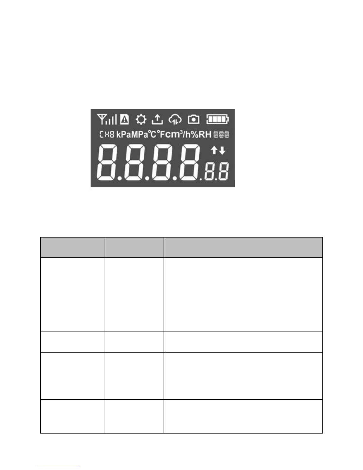
2.2 Display instruction
The screen display parameters are shown in table 2.2.
Table 2.2
Icon name
Meaning
Details
Signal
Wireless
signal
strength
indicator
≥25 full green
≥15 green for 3 bars
≥10 green for 2 bars
<10 green for 1 bar
0 null / signal tower icon only
SIM card
Card status
No card/unrecognized card
Configuration
Configuration
mode
When the configuration icon is lit, it
enters the configuration mode and the
device stops the data transmission.
Collection
Sensor data
collection
Collect sensor data regularly, the icon
lights, the device external feed, the
battery
┆
Photograph
┆
transmission
┆
collection
┆
configuration
┆
SIM card
┆
signal
┆
┄ device status
┄ channel NO./unit
┄ channel value/alarm
Page 14

10
sensor work
Transmission
Data
interaction
The device is communicating with the
server requesting the data.
Photograph
photograph
Taking photo/photo data acquisition
Battery
Power
indicator
Non-recharge
able battery
≥95% Full Green
≥85% 3 Green Bars
≥75% 2 Green Bars
≥65% 1 Green Bar
﹤65% Empty
12V DC
/110V~240V
AC
Adapter Icon displayed
on web.
Battery shows full on the
displayer
Rechargeable
Battery/Solar
power
≥95% Full Green
≥85% 3 Green Bars
≥75% 2 Green Bars
≥65% 1 Green Bar
<65% Empty
Channel NO.
Distinguish
between
different
sensor
channels
CH1~CH3: analog channel
CH4~CH6: RS485 channel
CH7~CH8: DI/PI
Unit
Sensor type
Pressure: kPa, MPa:
Temperature: ℃, ℉:
Height: cm, m
Page 15
11
Flow: cm³, m³
Flow rate: cm³/h, m³/h
Humidity: %RH
User defined: xxx
Channel value
Real-time
value of
sensor
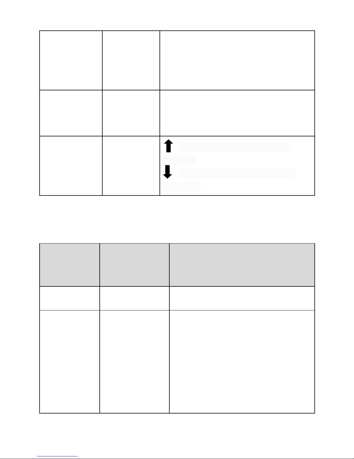
Alarm
Alarm status
reminder
over the upper limit of channel
threshold
below the lower limit of channel
threshold
2.3 Network mode
Table 2.3 network mode
Communicati
on mode
Zone
Standard/Frequency bands
2G
Global bands
GSM 850/900/1800/1900MHz
Multi-Bands
China
TDD-LTE B38/B39/B40/B41
FDD-LTE B1/B3/B8
TD-SCDMA B34/B39
WCDMA B1
CDMA 1X/EVDO BC0
GSM/GPRS/EDGE B3/B8
Page 16

12
EMEA/Korea/
Thailand/India
FDD-LTE B1/B3/B5/B7/B8/B20
WCDMA B1/B5/B8
GSM/GPRS/EDGE B3/B8
North America
FDD-LTE B2/B4/B12
WCMDA B2/B5
South America/
Australia/
New Zealand /
Tai Wan
TDD-LTE B40
FDD-LTE
B1/B2/B3/B4/B5/B7/B8/B28
WCDMA B1/B2/B5/B8
GSM/GPRS/EDGE B2/B3/B5/B8
Japan
FDD-LTE B1/B3/B8/B18/B19/B26
NB-IoT
Global bands
B1/B3/B8/B5/B20/B28
LoRa
433/470/868(Europe) /915(USA)
MHz transmission distance≤5km
(According to site environment)
2.4 Interface definition
All interfaces of Earth1006 are foolproof plug and each electrical
definition has different PIN number, please pay attention to checking.
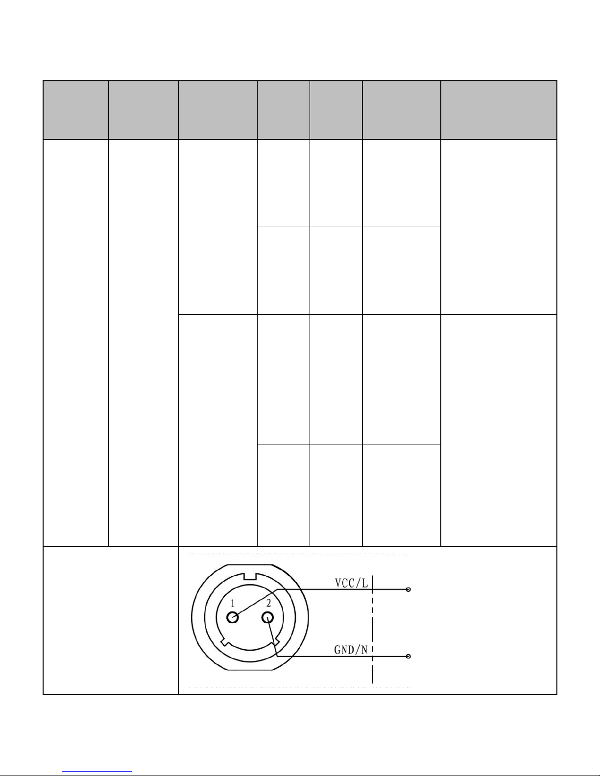
2.4.1 Power interface
The power interface corresponds to 2PINS terminal, the definition of
interface is shown in Table 2.4.
Page 17
13
Table 2.4 power interface
Interfa
ce type
Termin
al type
Power
supply
Pin
Defin
ition
Details
Note
Power
2PINS
Recharg
eable
battery/s
olar
power/12
VDC
1
VCC
Supply +
/solar
panel +
Non-rechargea
ble Battery has
no power
interface.
2
GND
Supply -
/solar
panel -
110V~24
0V AC
50~60Hz
1LAC L
Please pay
attention to
checking the
power supply
identification in
case of any
possible safety
accidents
2NAC N
Electrical
connection
Page 18
14
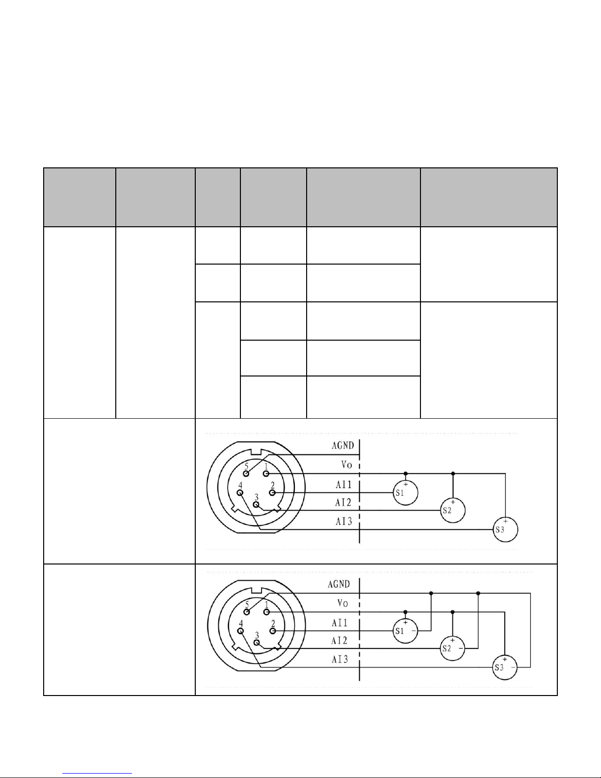
2.4.2 AI interface
AI interface corresponds to 5PINS terminal and there are 2-wire and
3-wire. The definition is shown in table 2.5.
Table 2.5 AI interface
Interfac
e type
Terminal
type
Pin
Definiti
on
Details
Note
AI
5PINS
5
AGND
Common port
feed≤100mA
1Vofeed
2
AI1
Analog input 1
0V~5V DC/
4mA~20mA DC
Input
current≤30mA
AI2
Analog input 2
AI3
Analog input 3
2-wire electrical
connection(4~20mA)
3-wire electrical
connection(0~5VDC)
Page 19
15
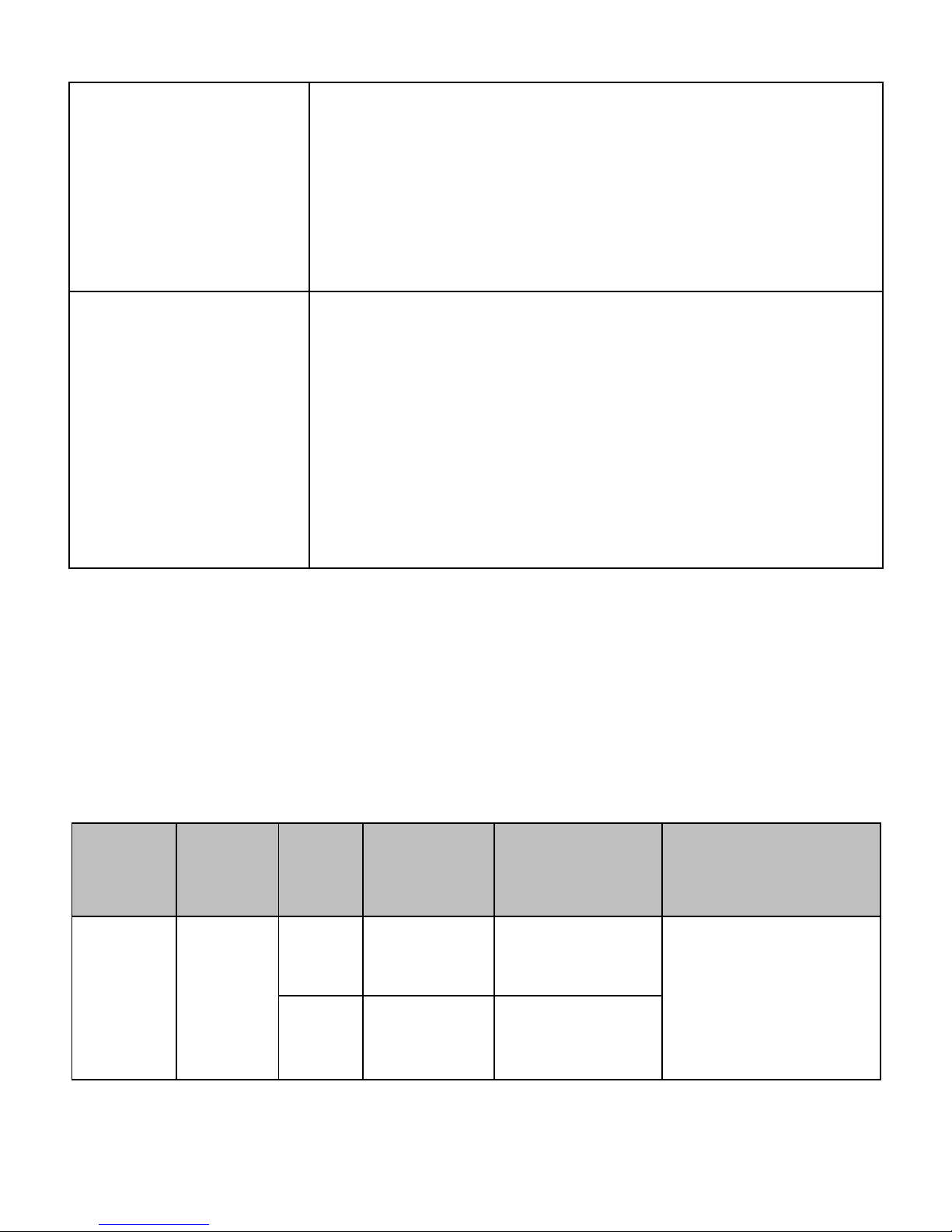
Channel Value
When there is no load, the current type channel value =
range ÷ (-4), for example, when the range is 2 MPa,
the channel value is -0.250, and the voltage type
channel value = random value.
Note
If the equipment has three 5-PIN terminals, they are
three separated AI ports, which can connect with three
different sensors. But the AI interfaces are
standard-alone interfaces, cannot be extended by using
the external junction box. Different types of sensor
channels can be distinguished based on the labels.
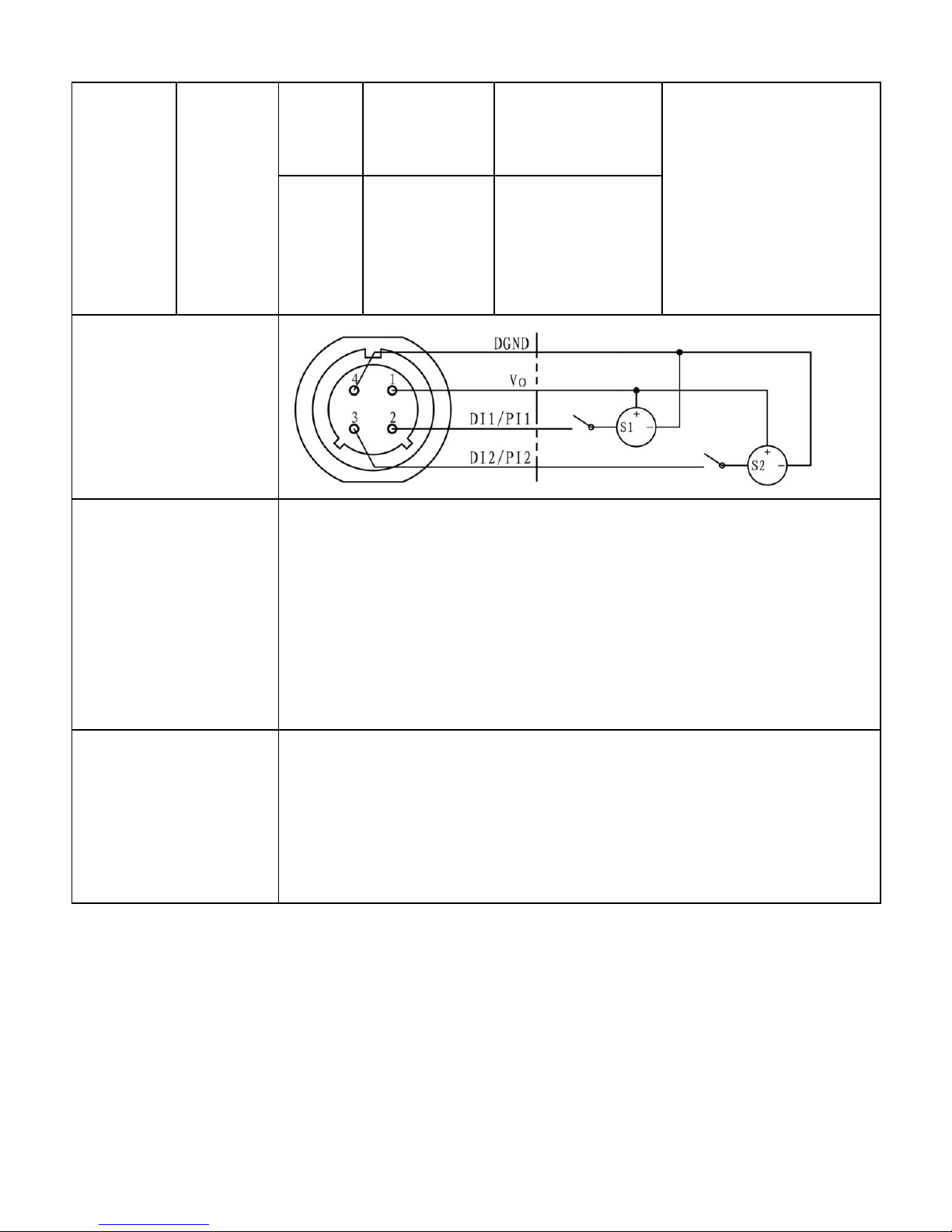
2.4.3 DI/PI interface
DI/PI interface corresponds to 4PINS terminal and the definition is shown
table 2.6.
Table 2.6 DI/PI interface
Interfa
ce type
Termin
al type
Pin
Definition
Details
Note
DI/PI
4PINS
4
DGND
Common port
feed≤100mA
1Vofeed
Page 20
16
2
DI1/PI1
Switch 1/
pulse 1 input
Low level 0~1V DC
High level 5~12V
DC
Pulse
frequency≤10Hz
3
DI2/PI2
Switch
2/pulse 2
input
electrical
connection
Channel Value
DI: At low level, the channel value is 0; at high level, the
channel value is 1.
When the * MST071 shift switch is raised (well cover
change), it turns on and outputs the high level.
PI: The channel value is 0.
Note
If the device has only one 4-PIN terminal, it can only
connect with one sensor as default, but if two channels are
required, exterior connection box would be necessary.
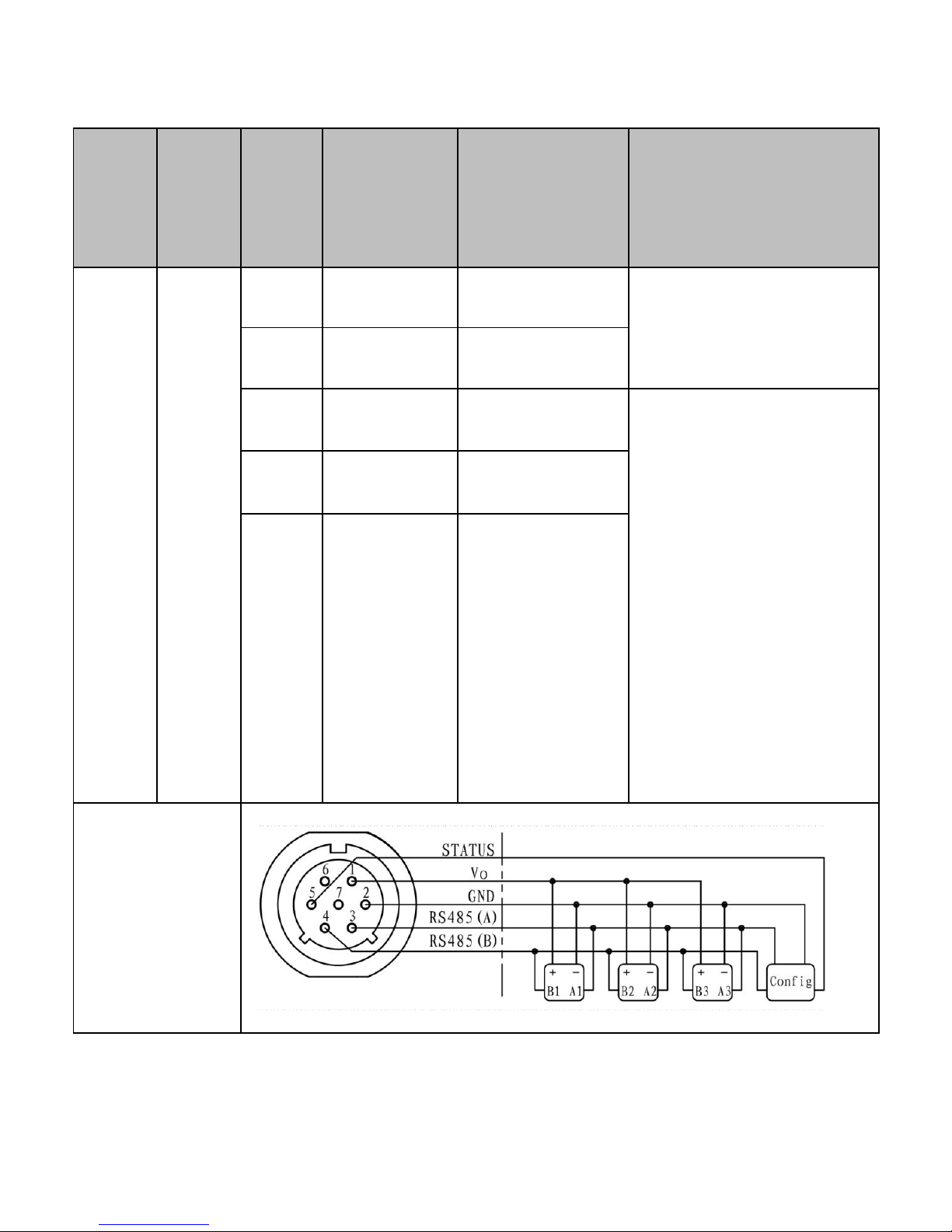
2.4.4 RS485 communication interface
RS485 interface corresponds to 7PINS terminal and the definition is
shown in table 2.7.
Page 21
17
Table 2.7 RS485 communication interface
Interf
ace
type
Term
inal
type
Pin
Definition
Details
Note
RS485
7PINS
2
GND
Common port
feed≤100mA
1Vofeed
3
RS485(A)
RS485(A)
Support max. 3-way
sensor parameter
analysis and also
suitable for device
configuration, support
MPM47xx
protocol/ModBus RTU
protocol of Micro
Sensor
4
RS485(B)
RS485(B)
5
Status
3.3V~12V
input, used for
configuration
detection
RS485
Electrical
connection
Page 22
18
Channel
Value
The channel value is 88.88 or 99.99 when there is no
load/subsidiary devices failure/abnormal configuration.
Note
If the device has only one 7-PIN terminal, it connects with one
sensor in default. If two or three sensors need to be
connected, the exterior connection box would be necessary.
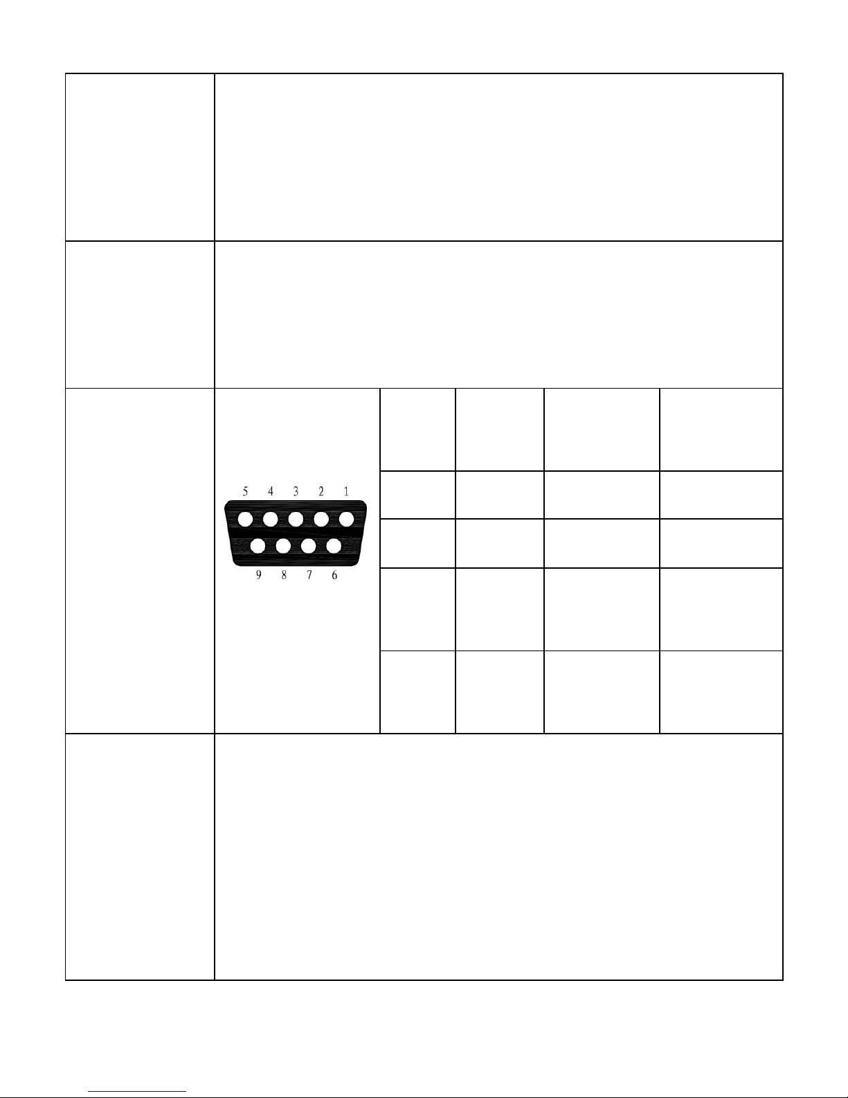
DB9 female
connector
definition
Pin
Wire
color
definition
details
1
brown
RS485(A)
RS485(A)
2
blue
RS485(B)
RS485(B)
5
black
GND
Common
port
6
grey
3.3V~12V
Power
input
Note
The interface configuration and RS485 Communication share
the 7-pin terminal, the other end is connected with a RS485
serial line via the standard DB9 female head socket. Please
note the Power pin (Pin 6)of the serial line needs the power
input to ensure the I/O detection is available and it can enter
the configuration mode.
Page 23
19
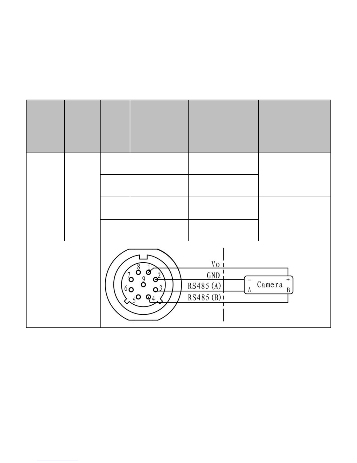
2.4.5 Camera interface
Camera interface corresponds to 9PINS terminal and the definition is
shown in table 2.8.
Table 2.8 camera interface
Interfa
ce
type
Termi
nal
type
Pin
Definition
Details
Note
Camera
9PINS
2
GND
Common port
feed≤500mA
1Vofeed
3
RS485(A)
RS485(A)
Specialized for
camera
4
RS485(B)
RS485(B)
Electrical
connection
3 Device configurations
3.1 configuration tool
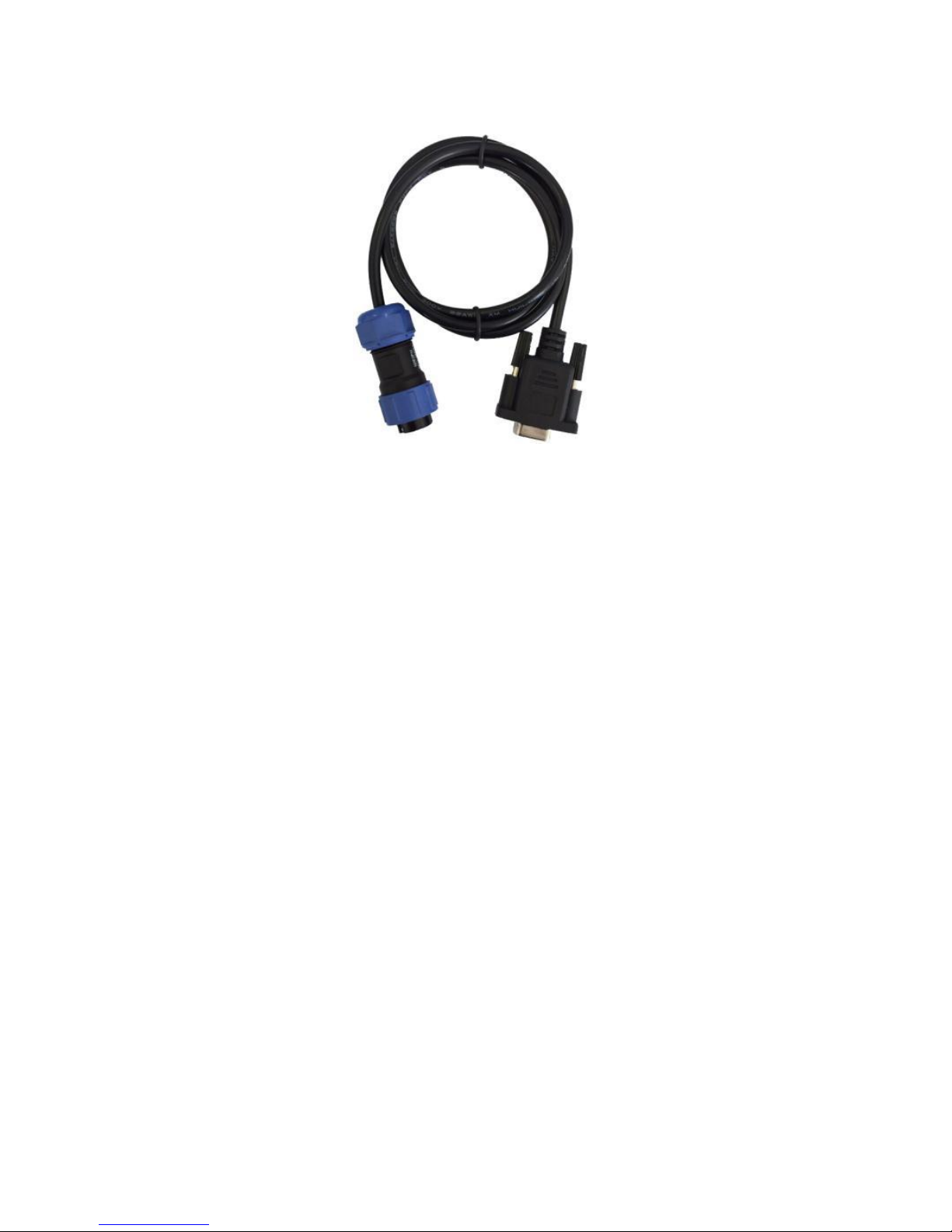
Each order shall be equipped with a configuration line, using a standard
DB9 female socket outlet, as shown in figure 3.1, and the customers
need to purchase a RS485 serial line by themselves.
Page 24
20
Please log on iot.microsensor.cn to download the configuration software.
Figure 3.1 DB9 configuration line
3.2 Local configuration method
After the device is powered on, connect the standard USB-RS485 serial
line to the PC, and connect the DB9 configuration cable to the device,
then run the configuration software.
The product comes with a standard DB9 configuration cable. Users need
to purchase the USB-RS485 serial line (Z-TEK ZE628 is recommended)
by themselves. Please note, when the RS485 interface is used in the
Configuration Mode, Pin 6 needs to be powered with 3.3V~12VDC for
the configuration mode I/O detection, otherwise it cannot enter the
configuration mode; In the configuration software, select the
communication port to set the baud rate to 115200, no parity bit, stop bit
1 bit, and open the serial port. (The serial port is open on the screen,
indicates that it is in the configuration mode)
Page 25
21
3.3 Remote configuration method
According to the corresponding account on the device, log in the big data
platform - Device Category - Edit, then the remote configuration can be
realized. The detailed method can be seen in the Help page of big data
platform.
3.4 Configuration options
Table 3.1 configuration options
Items
Configurati
on item
Configuration
selection
Configuration
operation
Configurat
ion
method
Basic
param
eters
Cure
param
eter
Device ID
xxxxxxxx
Factory setting, no
modification.
Hardware
version
1.0
Software
version
1.0
Device
type
MPM6861G/
MPM6881/
Earth1000/
MS6000/
Earth1006/
reserved
Page 26

22
Power
supply
type
battery/
mains supply/
adaptor/
solar energy
Remot
e
param
eter
Server IP
xxx.xxx.xxx.xxx
xxx: 0~255,
xxxxx: 0~65535
Under special
circumstances, the
device supports
SMS configuration,
SMS configuration
commands are as
follows, send SMS to
the center number
#@1064837639832
#PZYM:"115.29.194.
124"PZDK:"8080"
1064837639832 is
device card NO.
Local/rem
ote
configurati
on
Server port
xxxxx
APN
APN Switch
Open/Close
Access Point
name
Character size<32
Page 27

23
User name
Character
size<16(non-mandat
ory)
Code
Character
size<16(non-mandat
ory)
Collection
interval
1/5/10/30/60/360/
720/1440 mins
Alarm according to
the interval, default
30
Transmissi
on interval
1/5/10/30/60/360/
720/1440 mins
Collection interval ≤
transmission interval
≤ 24*collection
interval, default 30
Photograp
h interval
30/60/720/1440
mins
Default 1440
AI
interfa
ce
Signal
input
Null
Sensor physical
properties, DC input,
it is not
recommended to
modify, default
4~20mA
Local
configurati
on
0~5V
0.5~4.5V
0.5~2.5V
0.25~2.25V
4~20mA
Page 28
24
Collection
type
Pressure (KPa)
Sensor physical
properties, it is not
recommended to
modify
Pressure (MPa)
Temperature (℃)
Temperature (F)
Level (cm)
Level (m)
Humidity (RH)
Flow (cm³)
Flow (m³)
Flow rate (cm³/h)
Flow rate (m³/h)
pm2.5 (ug/m³)
null
Display
accuracy
1/2/3 decimal
places
The screen displays
the decimal number,
and the actual
upload is based on
three decimal
places. Default 3
Page 29

25
Upper limit
of the
range
32 bits Float,
keep 3 decimal
places
Sensor physical
properties, it is not
recommended to
modify
Lower limit
of the
range
32 bits Float,
keep 3 decimal
places
Sensor physical
properties, it is not
recommended to
modify
Power-on
delay
1~1000
*50ms, default 40
Image
alarm
Y/N
Default N
calibration
Zero calibration
Span calibration
RS485
interfa
ce
Baud rate
4800/9600/19200
/57600/115200bp
s
Default 9600
Local
configurati
on
Data bit
5/6/7/8
Default 8
Check bit
None/Even/Odd
Default None
Stop bit
01/02
Default 01
Page 30

26
Protocol
type
ModBus RTU/
MPM47xx/
Null
Default ModBus
RTU
Slave
address
01~99
Default 01
Function
code
03/04
Default 04
Initial
address
01~99
Default 01
Register
qty.
01~99
Default 04
Byte order
3210/2301/
1032/0123
Default 3210
Collection
type
Same with AI interface
Display
accuracy
Upper limit
of the
range
Page 31

27
Lower limit
of the
range
Power-on
delay
Display
accuracy
Image
alarm
DI/PI
interfa
ce
Signal
input
DI/PI/Null
Local
configurati
on
Trig mode
high/low level
Default high level
Alarm level
high/low level,
Only DI valid
Default high level
resolution
Only PI valid
32 bits Float,
keep 3 decimal
places
Collection
type
Only PI valid
Same with AI
interface
Display
accuracy
Only PI valid
Page 32

28
Upper limit
of the
range
Only PI valid
Lower limit
of the
range
Only PI valid
Power-on
delay
Only PI valid
Display
accuracy
Application
configuration
Lower
threshold
≥lower limit of range,
<upper threshold
Default 20% FS
Remote
configurati
on
Upper
threshold
≤upper limit of
range, >lower
threshold
Default 80% FS
others
Device address,
location, device
name, group
information,
migration value,
remark, etc.
Please refer to
Help page in data
platform
Page 33
29
4 Installation instruction
4.1 Installation tool
1 set drill and 1pc No. 3 screwdriver.
4.2 Installation method, dimension and instruction
4.2.1 Installation method
Wall-mounting and hoop-mounting type.
4.2.2 Installation instruction
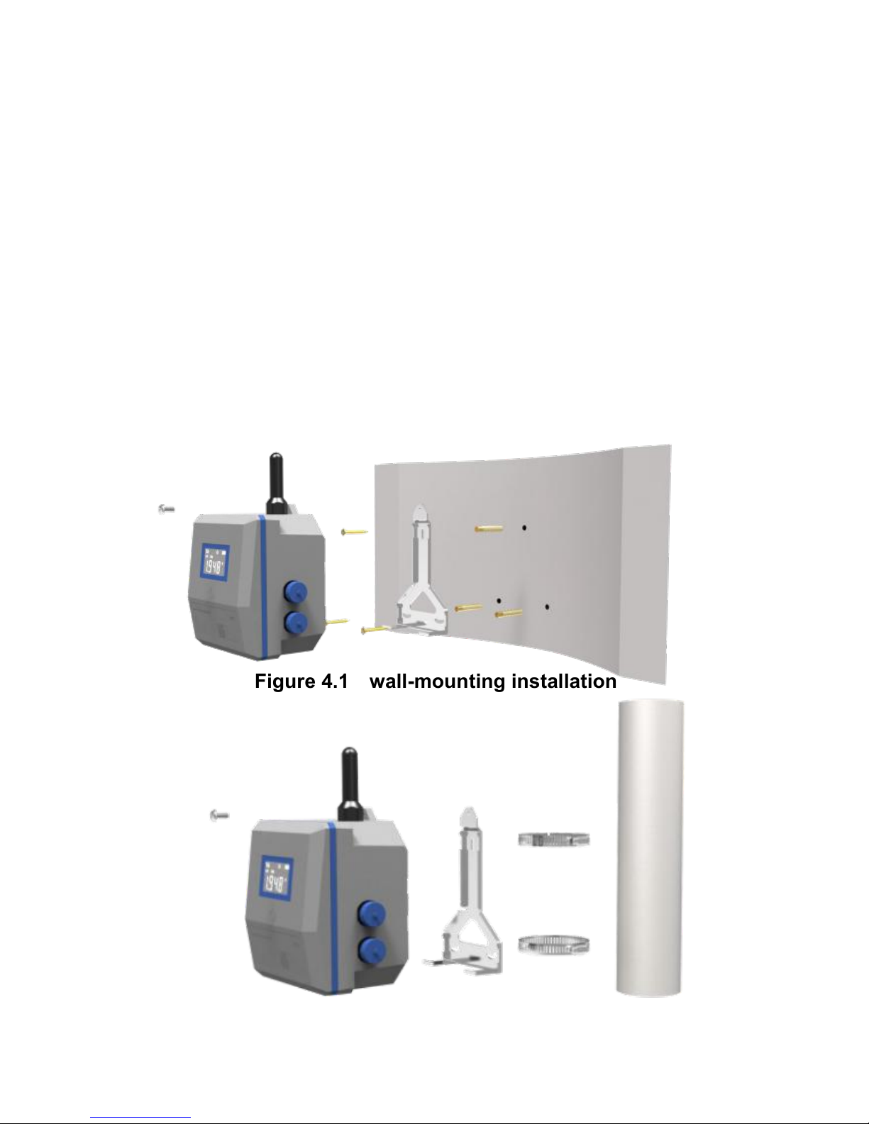
The installation of the Earth1006 remote monitoring terminal is shown in
figure 4.1 and 4.2.
Figure 4.1 wall-mounting installation
Figure 4.2 hoop-mounting installation
Page 34
30
4.2.3 Installation dimension
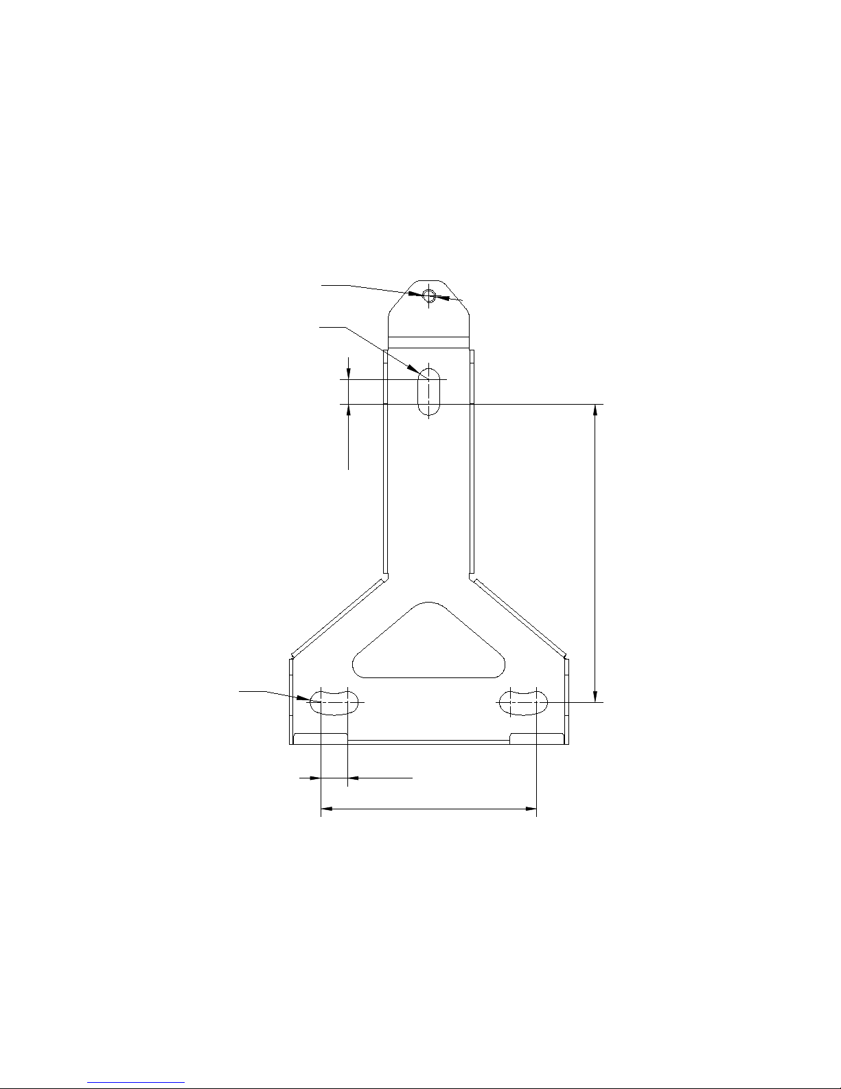
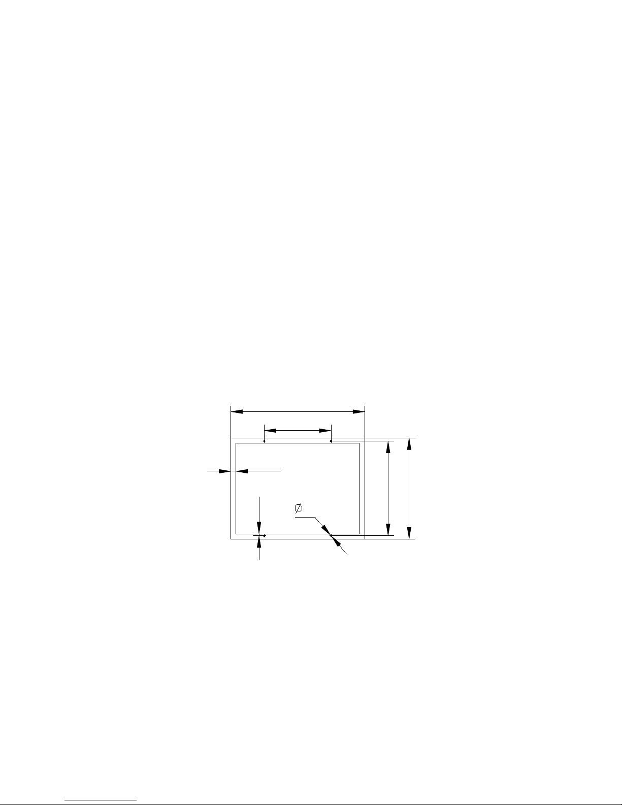
Wall-mounting type: 112mm×70mm, shown in figure 4.3.
Hoop-mounting type: φ70mm~φ180mm(stud diameter)
Unit: mm
M5
R4
110
9.2
80
R4
9.8
Figure 4.3 backboard dimension
4.3 SIM card installation
Step 1: open the top cover
Page 35

31
Use a Phillips screwdriver to remove the fastening screws (12pcs) that
secure the top cover to the housing, and then open the top cover.
Attention: the top cover and housing are connected by FPC flat wire.
Step 2: Remove the FPC flat wire from the control PCB socket of top
cover. (it is OK to skip to step 3)
Step 3: install SIM card
Turn over the top cover and find the communication PCB. Tap the yellow
key of SIM card holder in communication PCB, popping up the card slop
and then install the SIM card. After installation, please plug the FPC wire
back to the socket.
Attention: Be sure to disconnect the power when operating.
Step 4: install the top cover
Tighten the rubber sealing ring and secure the cover back to the lower
housing with the fastening screws.
Step 5: fastening screw
Use a Phillips screwdriver to tighten the captive screws (12pcs) between
top cover and housing.
Attention: For reliable protection, rubber sealing ring cannot be
dislocated.
Page 36
32
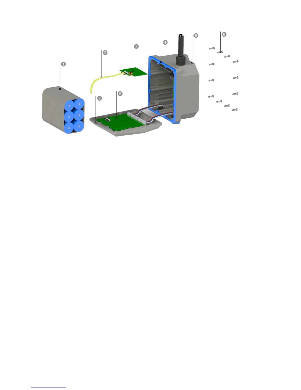
Figure 4.4 Dis-assembly diagram
Note:
1-battery,2-FPC flat wire,3-communciation PCB,4-sealing ring,5-lower
housing,6-fastening screw,7-top cover,8-controlling PCB
4.4 Device battery replacement
When using battery supply, the battery needs to be replaced periodically.
When you find the battery voltage from the data platform is lower than
13V, or the local battery is null, or there is no report for several days, it is
possible that the battery power is low and needs to be replaced. The
battery replacement procedure is as follows:
Step 1: open the top cover
Use a Phillips screwdriver to remove the fastening screws (12pcs) that
secure the top cover to the housing, and then open the top cover.
Page 37

33
Attention: the top cover and housing are connected by FPC flat wire.
Step 2: Remove the FPC flat wire from the control PCB socket of top
cover.
Step 3: replace new battery
When the battery is exhausted, it needs to replace the new battery. Turn
over the top cover, open the Velcro strip, remove the used battery and
then put on a new battery. Replace the used battery connector from the
control PCB socket with a new one and stick the strip.
Step 4: connect the FPC flat wire to control PCB socket of top cover.
Step 5: install top cover
Tighten the rubber sealing ring and secure the cover back to the lower
housing with the fastening screws.
Step 6: fastening screw
Use a Phillips screwdriver to tighten the captive screws (12pcs) between
top cover and housing.
Attention: For reliable protection, rubber sealing ring cannot be
dislocated.
4.5 Fixture
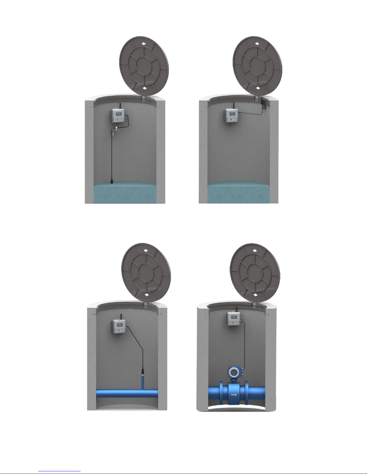
4.5.1 Underground installation examples
Page 38
34
Level Covers abnormal
Pressure Flow
Page 39
35
4.5.2 wall-mounting type
Required accessories: 1pc wall-mounting bracket, 3 pairs expansion
screw, 1pc M5 bolt.
Step 1: Drill holes on the wall / well wall according to the installation
dimension. Attention: please do not use heavy hammer to strike the wall
like brick wall, cement brick and red brick wall. It is suggested to use light
percussion drill which will make the hole size more accurate and
installation quality higher.
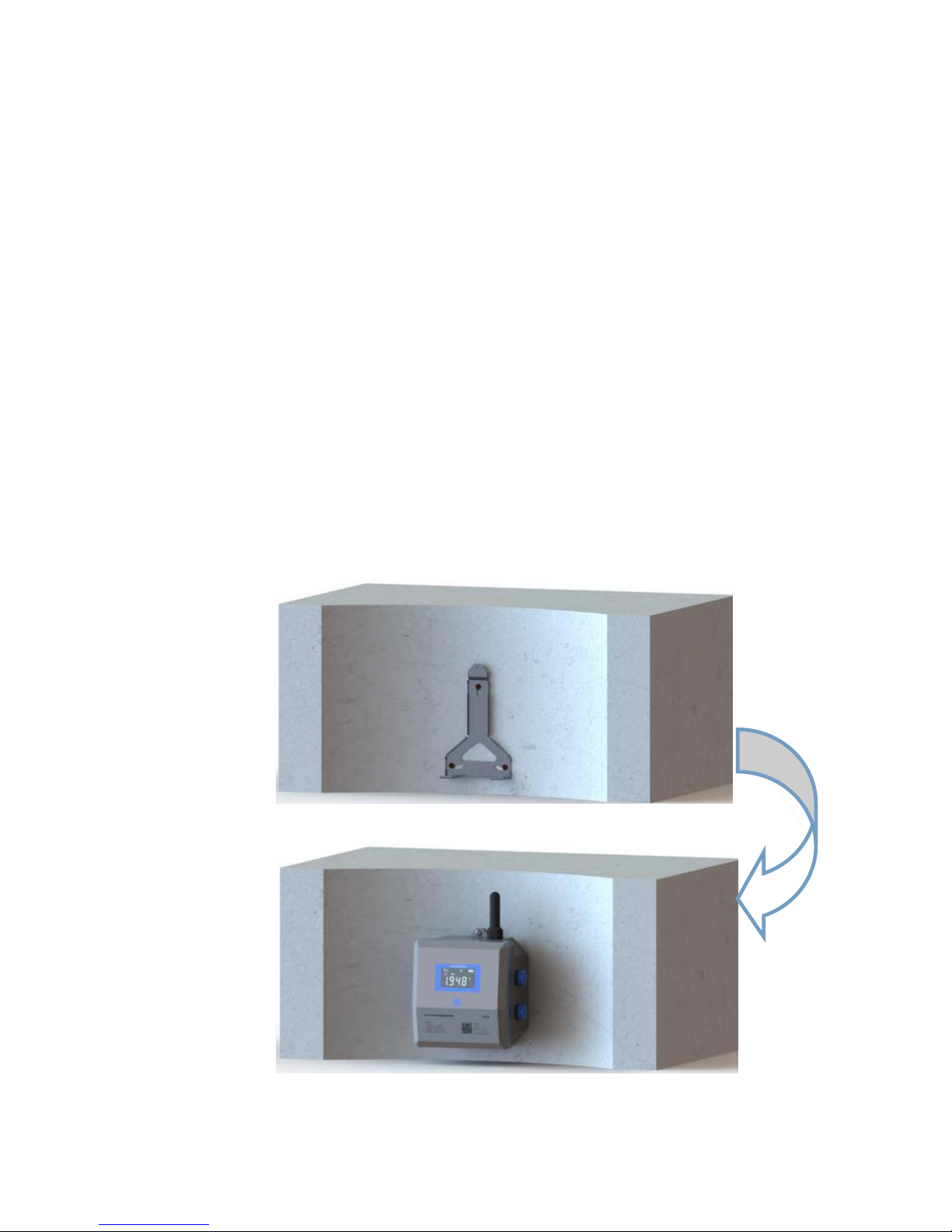
Step 2: Fix the wall-mounting bracket on the wall/well wall by expansion
screw, shown in figure 4.5.
Figure 4.5
Figure 4.5
Figure 4.6
Page 40
36
Step 3: fix the terminal on the bracket by M5 bolt, shown in figure 4.6.
Step 4: connect the slave device to terminal by aviation plug. The
installation is finished, and it is ready for operation.
Attention:for a reliable wireless transmission, it is suggested to
install the terminal within 50cm from the wellhead.
4.5.3 hoop-mounting type
Required accessories: 1pc wall-mounting bracket, 3pcs stainless steel
hoop, 1pc M5 bolt.
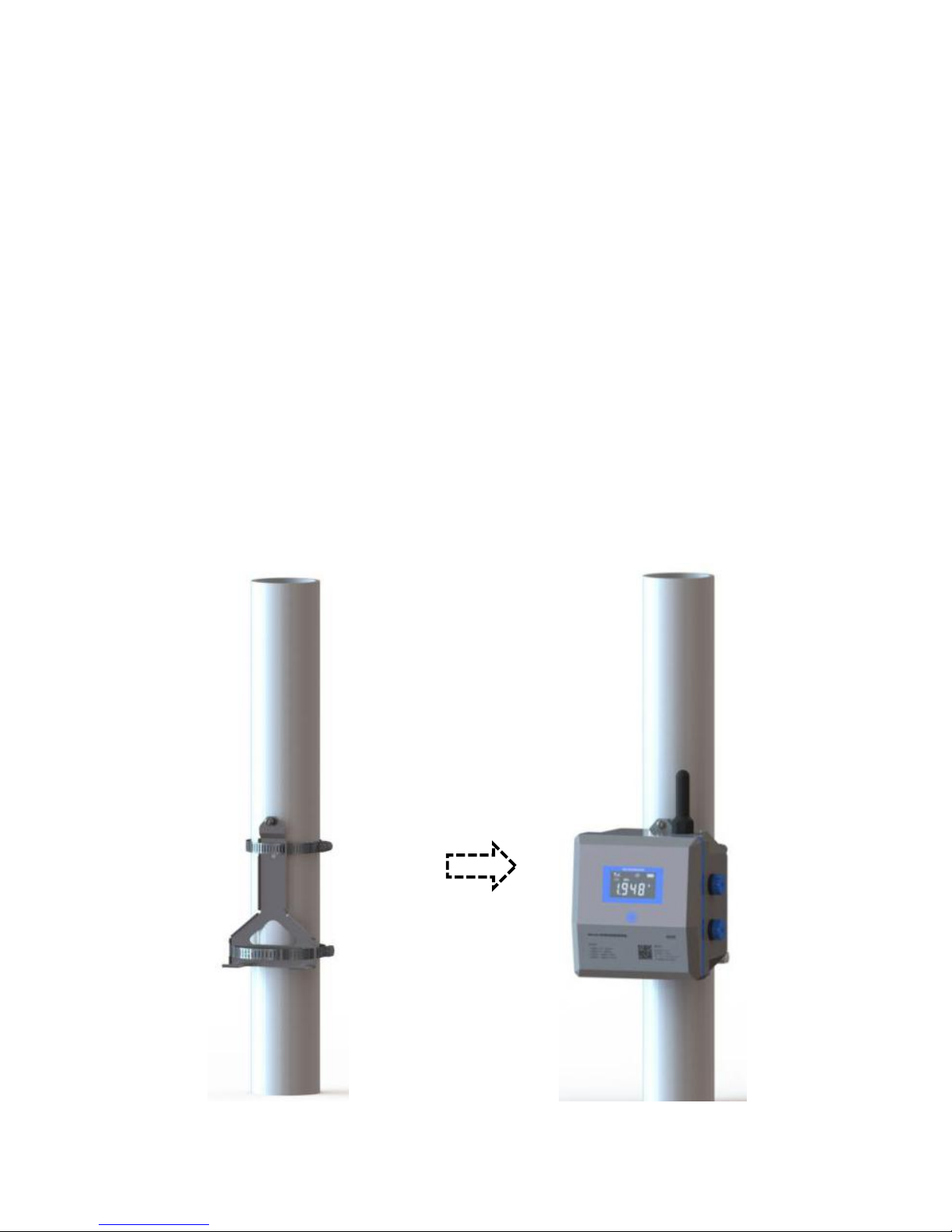
Step 1: fix the bracket on the stud by stainless steel hoop, shown in
Figure 4.7.
4.7 图 4.8
Figure 4.7 Figure 4.8
Page 41
37
Step 2: fix the terminal on the bracket by M5 bolt, shown in figure 4.8.
Step 3: connect the slave device to terminal by aviation plug. The
installation is finished and it is ready for operation.
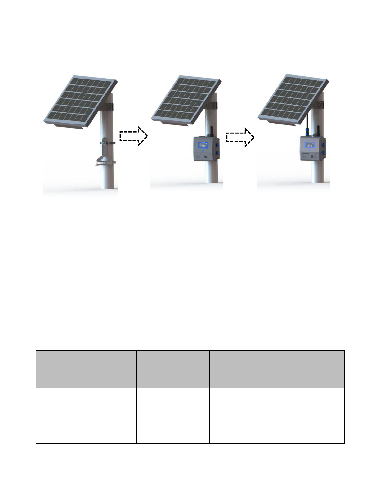
4.5.4 solar mounting type
Required accessories: 1pc wall-mounting bracket, 2pcs stainless steel
hoop, 1pc M5 bolt, 1pc solar panel (Customer self-purchased).
Step 1: Fix the solar panel on stud by solar panel fixing bracket (the
bracket is provided by the customer; the size of the solar panel is shown
in Figure 4.9).
Unit: mm
465
350
232.5
326
6
5
18
Figure 4.9
Step 2: fix the bracket on the stud by stainless steel hoop, shown in 4.10.
Step 3: fix the terminal on the bracket by M5 bolt, shown in figure 4.11.
Step 4: connect the solar panel to terminal, shown in figure 4.12.
Page 42
38
Step 5: connect the slave device to terminal by aviation plug. The
installation is finished and it is ready for operation.
Figure 4.10 Figure 4.11 Figure 4.12
5 Data platform instruction
For details, please check Help page from iot.microsensor.cn
6 FAQ
There will be some possible questions during application and the
solutions are shown in table 6.1.
Table 6.1 failure analysis and troubleshooting
Code
Failure
Possible
reasons
Treatment measure
1
No response
after starting
up
Slow induction
of the magnetic
bar
Touch with the magnetic bar at
2mm left/right side of the
induction spot
Page 43

39
Low battery
Check battery voltage and
replace the battery
Polarity error of
external power
supply
Check if the circuit and power
supply is normal and plug
polarity is correct.
2
No display
Sleeping mode
Active the device by magnetic
bar
Connection
error for FPC
screen
While Installing SIM card or
replace battery, please ensure
the FPC connection is reliable.
Low battery
Check battery voltage and
replace the battery
3
Parameters
setting
unavailable
No response
after the
RS485 serial
line connection
Check if RS485 line is well
connected and if the PIN 6 of
RS485 line is powered.
Error of series
Parameters
setting
Check if the serial port
parameters of the parameter
software are selected correctly.
Incorrect serial
port selection
of PC
Check if COM port is correct.
Page 44

40
4
Abnormal
data
transmission
Connection
error
Check if connection is normal
External device
failure
Check the external device
Configuration
error of
parameter
setting
software
Check the port configuration of
parameter setting software
APN not
configured
Check with the local SIM card
provider if the APN service is
available; if it is available,
configure on the device.
SIM card error
Check if SIM card is inserted
well
Antenna
connection
Fix the antenna connection
part firmly
SIM card
arrearage
Recharge for SIM card
SIM card has
no digital
service
Open digital service for SIM
card
Page 45

41
The signal of
device location
is weak
Check the signal strength of
the device location and adjust
the installation position to
ensure the signal strength is in
the best condition
Low battery
Check battery voltage and
replace the battery
Information
configuration
error of remote
server
Check remote address
information to ensure a correct
configuration.
5
Others
\
Please contact manufacturer
for other special failure.
7 Responsibility
Within one year from the delivery date, we shall repair or replace the
instrument with any quality fault caused by material parts or our
manufacturing technique free of charge. For non-quality malfunction
during user’s operation, we are in charge of repair. But, the material cost
and the shuttle transportation fees should be borne by users.
Page 46

 Loading...