

Page 1
4 10/100/1000TX + 1 Mini-GBIC Switch
User Manual
MS453510
Page 2

CE Mark Warning
This is a Class-A product. In a domestic environment this product may cause
radio interference in which case the user may be required to take adequate
measures.
Page 3

Content
INTRODUCTION ............................................................................... 1
Features ............................................................................................................... 1
Package Contents ................................................................................................ 2
HARDWARE DESCRIPTION ............................................................ 3
Physical dimension .............................................................................................. 3
Front Panel ........................................................................................................... 3
Rear Panel ........................................................................................................... 3
LED Indicators ...................................................................................................... 4
Desktop Installation .............................................................................................. 6
Attaching Rubber Feet .................................................................................. 6
Power On ............................................................................................................. 6
NETWORK APPLICATION ............................................................... 7
Small Workgroup .................................................................................................. 7
Segment Bridge ................................................................................................... 7
TROUBLESHOOTING ...................................................................... 9
Incorrect connections ........................................................................................... 9
Faulty or loose cables ..................................................................... 9
Non-standard cables ....................................................................... 9
Improper Network Topologies ....................................................... 10
Diagnosing LED Indicators ................................................................................. 10
TECHNICAL SPECIFICATION ....................................................... 11
APPENDIX ...................................................................................... 14
10 /100BASE-TX Pin outs .................................................................................. 14
10/100Base-TX Cable Schematic ...................................................................... 14
10/100/1000Base-TX Pin outs ........................................................................... 15
10/100/1000Base-TX Cable Schematic ............................................................. 16
Page 4

Page 5

Introduction
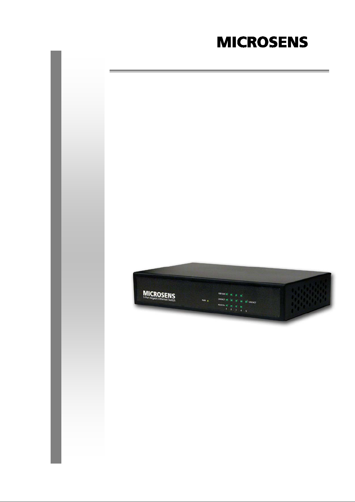
The 4 10/100/1000TX + 1 Mini-GBIC Switch is a multi-port Switch that can be
used to build high-performance switched workgroup networks. The Switch is
targeted at workgroup or department.
The 4 10/100/1000TX + 1 Mini-GBIC Switch features a “store-and-forward
“ switching scheme that offers low latency for high-speed networking and allows
the switch to auto-learn and store source address in a 8K-entry MAC address
table.
The 4 10/100/1000TX + 1 Mini-GBIC Switch has 4 auto-sensing 10/100/1000
Base-TX RJ-45 ports plus one MINI GBIC slot that enables extended distance
connection.
Features
Conform to IEEE802.3 10BASE-T, IEEE802.3u 100BASE-TX Fast Ethernet,
IEEE 802.3ab 1000Base-T, IEEE 802.3z Gigabit Fiber, IEEE802.3x Flow
control and Back pressure
Store-and-Forward switching architecture
Auto-MDIX on all ports
10 Gbps back-plane
N-Way Auto-Negotiation
IEEE802.3x Flow control
Back pressure with half duplex (10/100Mbps)
Flow control with full duplex (10/100/1000Mbps)
8K MAC address table
112Kbytes memory buffer
True non-blocking switching
1
Page 6
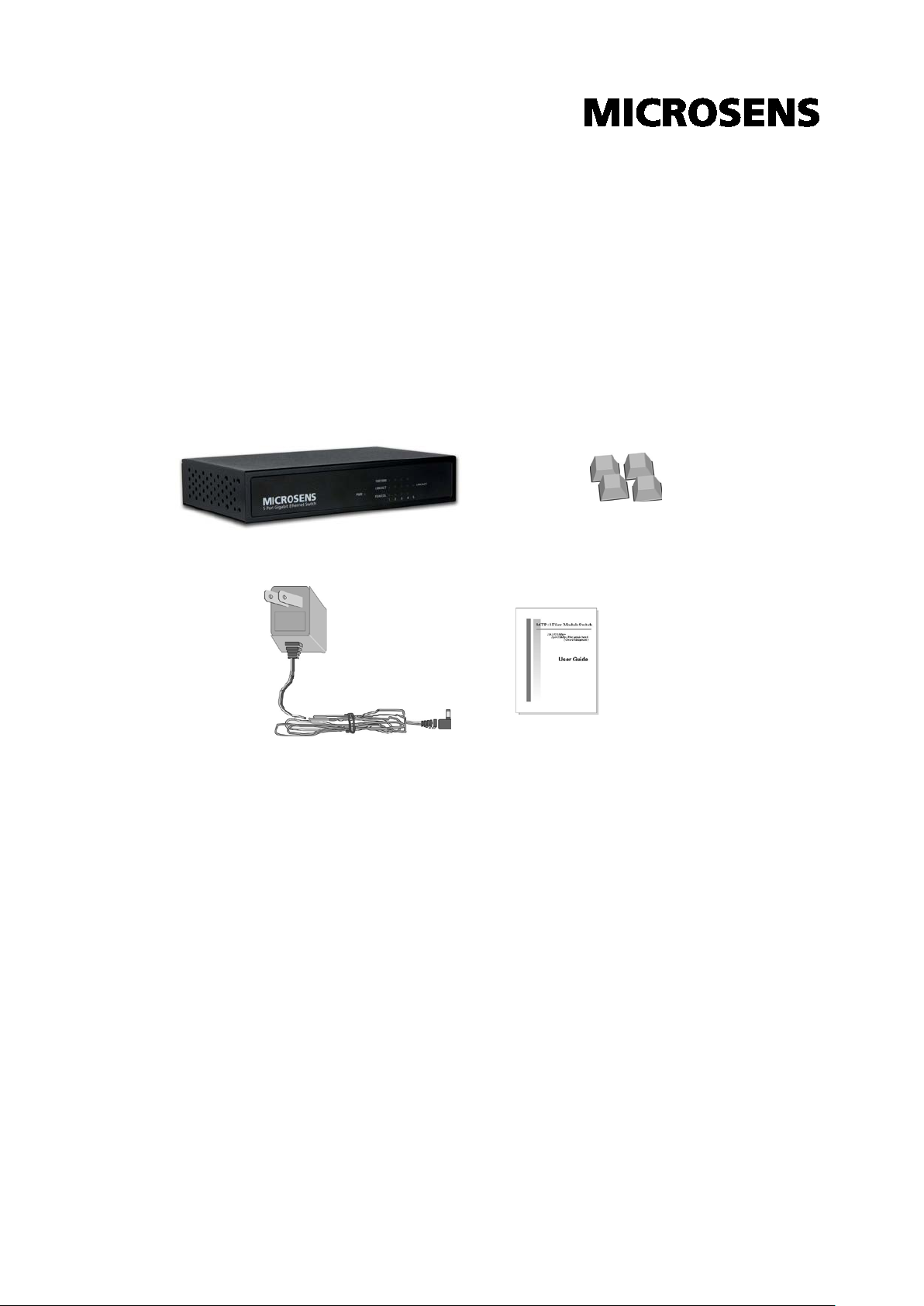
Package Contents
Unpack the contents of the 4 10/100/1000TX + 1 Mini-GBIC Switch and verify
them against the checklist below:
4 10/100/1000TX + 1 Mini-GBIC Switch
DC Power Cord
Four Rubber Pads
User Manual
4 10/100/1000TX + 1 Mini-GBIC Switch Four Rubber Pads
DC Power Adapter
Package Contents
User Manual
Compare the contents of your 4 10/100/1000TX + 1 Mini-GBIC Switch package
with the standard checklist above. If any item is missing or damaged, please
contact your local dealer for exchanging.
2
Page 7

Hardware Description
This section mainly describes the hardware of the 4 10/100/1000TX + 1
Mini-GBIC Switch, and gives a physical and functional overview on certain
switch.
Physical dimension
The 4 10/100/1000TX + 1 Mini-GBIC Switch physical dimension is
32.5 mm
(L x W x H).
165 x 100 x
Front Panel
The Front Panel of the 4 10/100/1000TX + 1 Mini-GBIC Switch consists of LED
Indicators and a reset button. Please refer to the LED Indicator section for LED
description.
Reset button:
back to the default settings. Press the button more than 5 seconds, and then
the switch will restart and set all configurations back to the default settings.
it provides an easy way for user to reset the configuration
Rear Panel
The rear panel consist the 4 10/100/1000Base-TX RJ-45 port, one Mini GBIC slot
and DC Power Jack as shown in figure. The switch will work with DC in the range
of 12V/0.8A.
3
Page 8
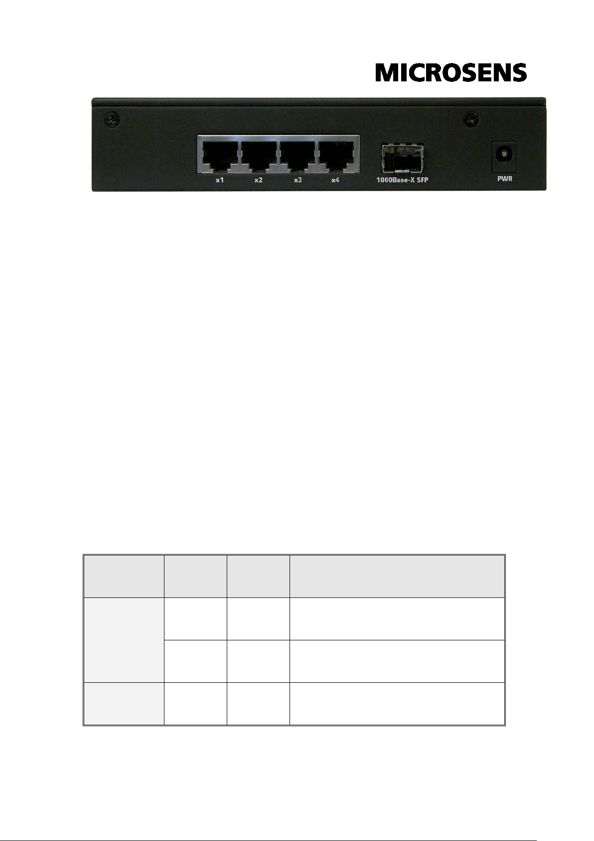
The port is operating at the speed of
The Rear Panel of 4 10/100/1000TX + 1 Mini-GBIC Switch
RJ-45 Ports (Auto MDI/MDIX):
10Base-T, 100Base-TX or 1000Base-T connections.
In general,
means connecting to a workstation or PC. Therefore,
would allow connecting to another Switch or workstation without changin g
non-crossover or crossover cabling.
Mini GBIC slot:
There is one LED indicator for Mini GBIC port – LNK/ACT.
means connecting to another Hub or Switch while
MDI
The MINI GBIC module is optional, and with 3.3V supported.
4x 10/100/1000 N-way auto-sensing for
Auto MDI/MDIX
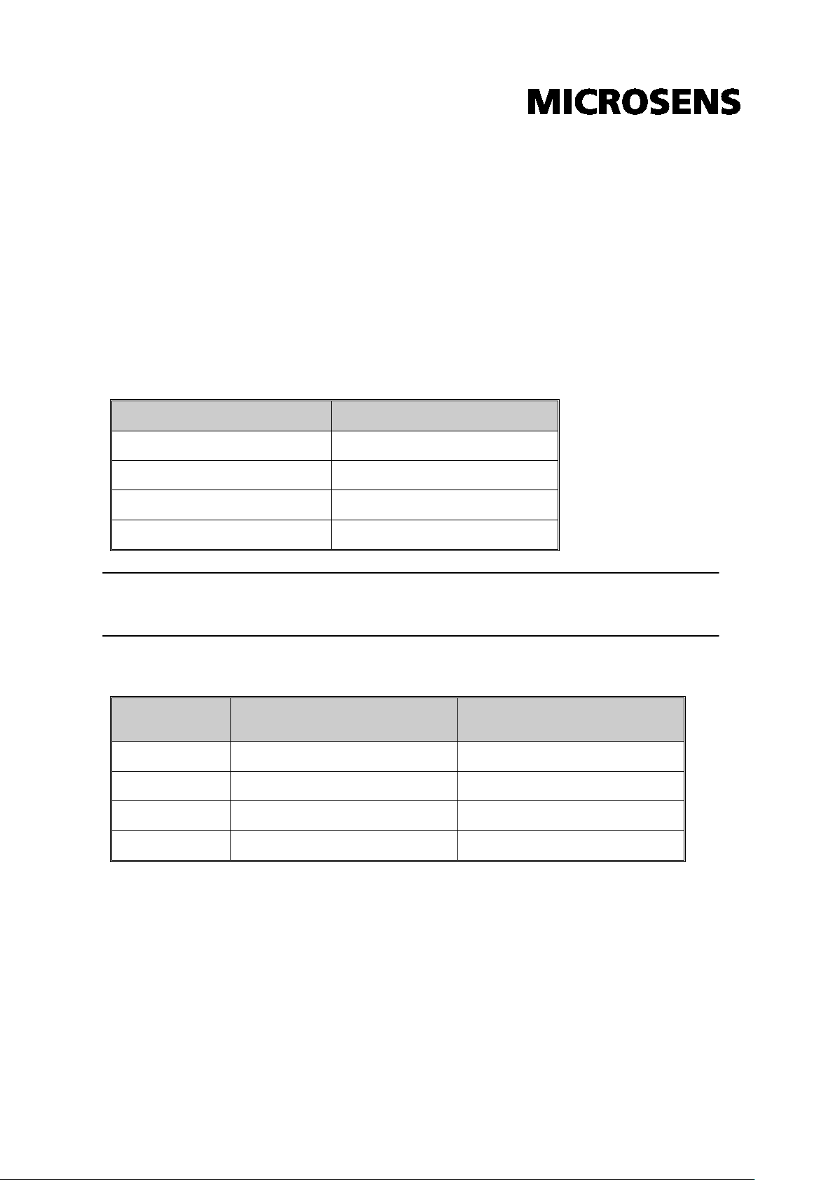
LED Indicators
The LED Indicators display the real-time information of systematic operation
status. Please see the definition of the LED indicators as below:
MDIX
LED Status Color Description
On Green Power On
Power
Off --
100/1000
4
On Green
No Power inputs or Power cord
disconnected
1000Mbps.
Page 9

The port is operation at the speed of
In 10Mbps mode or no device
The port is well connected with the
The port is in processing of receiving
The port is operating in Full-duplex
Collision of Packets occurs in the
Half-duplex mode or no device
The port is well connected with the
receiving
On Yellow
100Mbps.
Off --
attached
On Green
device.
LNK /ACT
FDX /COL
LNK /ACT
(MINI GBIC)
Blinks Green
or transmitting data.
Off -- No device attached.
On Yellow
mode.
Blinks Yellow
port.
Off --
attached.
On Green
device.
The port is in processing of
Blinks Green
or transmitting data.
Off --
The Definition of LED Indicators
5
No data transmitted or no device
connected
Page 10

Desktop Installation
Set the switch on a sufficiently large flat space with a power outlet nearby. The
surface where you put the switch should be clean, smooth, level and sturdy.
Make sure there is enough clearance around the switch to allow att achment of
cables, power cord and allow air circulation.
Attaching Rubber Feet
A. Make sure mounting surface on the bottom of the switch is grease and dust
free.
B. Remove adhesive backing from your Rubber Pads.
C. Apply the Rubber Feet to each corner on the bottom of the switch. These
footpads can prevent the switch from shock/vibration.
Power On
Connect the power adaptor to the power jag on the rear panel of the switch. The
other side of power adaptor connects to the power outlet. The external power
supply in the switch works with DC power in 12V/0.8A. Please check with the
power indicator on the front panel to see if power is properly supplied.
6
Page 11

Network Application
This section provides user a few samples of network topology in witch the switch
is used. In general, the 4 10/100/1000TX + 1 Mini-GBIC Switch is designed as a
segment switch. That is, with its address table (8000 MAC address) and high
performance, it is ideal for interconnecting networking segments.
PC, workstations, and servers can communicate each other by directly
connecting with 4 10/100/1000TX + 1 Mini-GBIC Switch. The switch
automatically learns nodes address, which are subsequently used to filter and
forward all traffic based on the destination address.
By using Uplink port, the switch can connect with another switch or hub to
interconnect other small-switched workgroups to form a larger switched network.
Meanwhile, you can also use fiber ports to connect switches. The distance
between two switches via fiber cable depends on the type of fiber transceiver.
Small Workgroup
The 4 10/100/1000TX + 1 Mini-GBIC Switch can be used as a standalone switch
to which personal computers, server, printer server, are directly connected to
form small workgroup.
Segment Bridge
For enterprise networks where large data broadcasts are constantly processed,
this switch is an ideal solution for department users to connect to the corporate
backbone.
7
Page 12

Two 4 10/100/1000TX + 1 Mini-GBIC Switches with PCs, print server, and local
server attached, are both connected to the core switch. All the devices in this
network can communicate with each other through the 4 10/100/1000TX + 1
Mini-GBIC Switch. Connecting servers to the 4 10/100/1000TX + 1 Mini-GBIC
Switch allows users accessing the data on server. By using fiber ports to connect
switches, the distance between two switches depends on the type of fiber
transceiver.
8
Page 13

Troubleshooting
This section is intended to help user to solve the most common problems on the4
10/100/1000TX + 1 Mini-GBIC Switch.
Incorrect connections
The switch port can auto detect straight or crossover cable when the switch link
with other Ethernet device. For the RJ-45 connector should use correct UTP or
STP cable, 10/100Mbps port use 2 pairs twisted cable and Gigabit 1000T port
use 4 pairs twisted cable. If the RJ-45 connector is not correct pin on right
position then the link will fail. For fiber connection, please notice that fiber cable
mode and fiber module should be match.
Faulty or loose cables
Look for loose or obviously faulty connections. If they appear to be OK, make
sure the connections are snug. If that does not correct the problem, try a different
cable.
Non-standard cables
Non-standard and miss-wired cables may cause numerous network collisions
and other network problem, and can seriously impair network performance. A
category-5 cable tester is a recommended tool for every 100Base-T network
installation.
RJ-45 ports:
cable for RJ-45 connections: 100Ω Category 3, 4 or 5 cable for 10Mbps
use unshielded twisted-pair (UTP) or shield twisted-pair ( STP )
9
Page 14

connections or 100Ω Category 5 cable for 100Mbps connections. Also be sure
that the length of any twisted-pair connection does not exceed 100 meters (328
feet). Gigabit port should use Cat-5 or cat-5e cable for 1000Mbps connections.
The length does not exceed 100 meters.
Improper Network Topologies
It is important to make sure that user have a valid network topology. Common
topology faults include excessive cable length and too many repeaters (hubs)
between end nodes. In addition, user should make sure that network topology
contains no data path loops. Between any two ends nodes, there should be only
one active cabling path at any time. Data path loops will cause broadcast st orms
that will severely impact network performance.
Diagnosing LED Indicators
The switch can be easily monitored through panel indicators to assist in
identifying problems, which describes common problems you may encounter and
where user can find possible solutions.
If the power indicator does tur n on when the power cord is plugged in, user may
have a problem with power outlet, or power cord. However, if the swit ch powers
off after running for a while check for loose power connections, power losses or
surges at power outlet. If the problem still cannot be resolved, contact the local
dealer for assistance.
10
Page 15

duplex/
Technical Specification
This section provides the specifications of 4 10/100/1000TX + 1 Mini-GBIC
Switch.
IEEE 802.3 10BASE-T Ethernet
IEEE 802.3u 100BASE-TX Fast Ethernet
Standard
Protocol
Technology
Transfer Rate
IEEE 802.3ab 1000Base-T
IEEE 802.3z Gigabit Fiber
IEEE 802.3x Flow Control and Back-pressure
CSMA/CD
Store-and-Forward switching architecture
14,880 pps for 10Mbps
148,800 pps for 100Mbps
1,488,000 pps for 1000Mbps
Per RJ-45 port:
100/1000, Link/Activity, Full
LED Indicators
Collision
Per MINI GBIC:
Per unit:
Power
11
Link/Activity
Page 16

10BASE-T: 2-pair UTP/STP Cat. 3, 4, 5 cable
Power
Operating
Operating
EIA/TIA-568 100-ohm (100m)
100BASE-TX: 2-pair UTP/STP CAT. 5 cable
Network Cable
EIA/TIA-568 100-ohm (100m)
Gigabit Copper: 4 pair UTP/STP CAT. 5 cable
EIA/TIA 568 100-ohm (100M)
Gigabit copper: 4 x RJ-45 with Auto-MDIX
Connector
MINI GBIC: 1 x MINI GBIC socket (3.3v)
Back-plane
MAC address
Memory Buffer
Dimensions
Power Supply
Consumption
10Gbps
8K Mac with Auto Learning
112Kbytes
165 x 100 x 32.5 mm (L x W x H)
External power DC 12V/0.8A
6.2 Watt (maximum)
0℃ to 45℃ (32℉ to 113℉)
Temperature
10% to 90% (Non-condensing)
Humidity
12
Page 17

EMI
CE
13
Page 18
Pin Number
Assignment
1
Tx+
2
Tx-
3
Rx+
6
Rx-
1
Receive Data plus (RD+)
Transmit Data plus (TD+)
2
Receive Data minus (RD-)
Transmit Data minus (TD-)
3
Transmit Data plus (TD+)
Receive Data plus (RD+)
6
Transmit Data minus (TD-)
Receive Data minus (RD-)
Appendix
10 /100BASE-TX Pin outs
With10 /100BASE-TX cable, pins 1 and 2 are used for transmitting data, and pins
3 and 6 for receiving data.
RJ-45 Pin Assignments
[NOTE]
wire pair.
The table below shows the 10 / 100BASE-TX MDI and MDI-X port pin outs.
“+” and “-” signs r epresent the polarity of the wires that make up each
Pin MDI-X Signal Name MDI Signal Name
10/100Base-TX Cable Schematic
The following two figures show the 10/100Base-TX cable schematic.
14
Page 19

Straight-through cable schematic
Cross over cable schematic
10/100/1000Base-TX Pin outs
The following figure shows the 10/100/1000 Ethernet RJ-45 pin outs.
15
Page 20

10/100/1000Base-TX Cable Schematic
Straight through cables schematic
Cross over cables schematic
16
 Loading...