

Page 1
MICROSENS
English
Operation and Installation manual for
Ethernet 6 Port Switch 5 x 10Base-T, 1 x
100Base-FX
MS453080PM/MS453081PM
43/11PK
1.
Address assignment in the network
The switch includes a layer 2 address management (self learning), which supports up to 2.048 MAC addresses. To store the
data and the addresses the switch has 1 MBit memory. The
storage of the addresses is done in dynamic assignment after
receiving a correct data packet. The value for the “Aging” is 300
seconds. This means that unused addresses are deleted out of
the memory after 5 minutes.
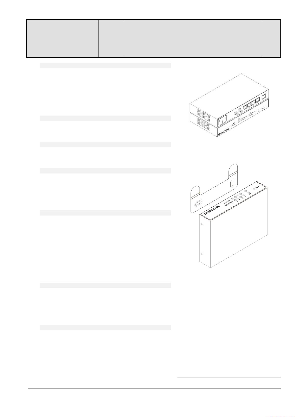
Fig. 1(MS453081-PM)
(MS453080-PM: without Fiber-Por)t
Fig. 2: Wall mounting
2.
Power supply
The power supply is realised with an integrated power supply.
This power supply can delivery up to 60 W.
3.
Wall mounting (optional)
Included accessory is the wall bracket which allows to mount the
switch very easy onto walls (see Fig. 2)
4.
Connection at twisted pair ports
Due to the auto crossing function of the twisted pair ports no
different patch cords, crossed or uncrossed, are necessary. The
switch is detecting the pinout automatically and configures itself.
This allows to connect end devices and switches with the same
patch cord.
5.
Configuration of the fiber uplink port (MS453081PM)
The duplex mode of the fiber uplink can be set manually by
management to half or full duplex. A LED indicates the full duplex mode (LED on). In half duplex mode this LED has the function of collision indication (flashing).
Default-Setup: full duplex
6.
7.
Networkmanagement
A powerful networkmanagement is integrated in the system.
The agent can be activated by using MICROSENS “Device Man-
ager” (is not part of this delivery).
The passwords for telnet/http-access are listed in fig. 4.
You need “Divce Manager V3.60” or higher
Power over Ethernet (IEEE802.3af)
The integrated Power-over-Ethernet function, provides at all 4
LAN-Ports the full power of 15.4W. All classes (0..4) are supported. The Twisted-Pair Uplink (Port 6) can be used for “Powered Device (PD)” applications.
All electrical parameters are permanent monitored, the system
will shut-down power instantly, while limits are exceeded.
For activation please use “Power Management” in the management.
Fig. 3: Aktivierung Power-over-Ethernet
• Disabled: IEEE 802.3af deactivated, no power
for Devices (PDs)
• Enabled: IEEE 802.3af activated, automatic
power-negotiation
• Force Mode: fixed power, no power-negitiation
Fig. 4: Passwords for telnet-/http-access
• public read only
• user limited read/write at http,
read-only at telnet
• admin unlimited read/write
Technical changes reserved
MICROSENS GmbH & Co. KG - Kueferstr. 16 - D-59067 Hamm / Germany - Tel. +49 2381/9452-0 - Fax -100 -
www.microsens.com
Page 2

8.
LED displays
The switch includes multiple LEDs for diagnostics. The function
of these LEDs is described in figure 5.
Fig. 5: LED functions
PWR
Power, ready for operation
FDX
Connection in full duplex mode
Flashing: Collision during a connection
in half duplex mode
LNK /
ACT
On: Connection of the related port
working (only port 1-4)
Flashing: Data received on this port
POE On: POE is active
9.
Reset
The switch is equipped with two reset push buttons (see fig. 1).
With the first push button (RESET) the switch can manually
resetted during the operation. Releasing the push button erases
the memory and re-initialises all connections.
Resetting the installation switch does not affect the network
management. Information like the TCP/IP address, switch configuration etc. is stored in a non-volatile memory.
The reset push button has another function. Pressing the Reset
push button for approximately 5 seconds will issue a management agent IP-request in case of the installation switch is network management enabled. In this way a new or first-time IPaddress can be allocated.
With a second reset push button (FACTORY RESET) the settings
of the switch for Cos, PoE, hardware configuration and VLAN will
be restored to factory defaults. Thus the fault configurations,
especially VLAN-settings which could lead to a non-reaching of
the agent can be deleted. Network management parameters like
e. g. the TCP/IP address are not affected.
10.
Safety notes
DANGER! Optical components can transmit laser light.
ATTENTION: Infrared light, which is used at the fiber optic data
transmission is not visible for the human eye, but can still cause
damages.
To avoid damages at the eyes, never look direct into the outputs
of the optical components or fibers. Danger of going blind! All
unused port must covered with caps. Activate transmission line
only when all connections are done. The active laser components
used in this product comply to the laser class 1
Technical changes reserved
MICROSENS GmbH & Co. KG - Kueferstr. 16 - D-59067 Hamm / Germany - Tel. +49 2381/9452-0 - Fax -100 -
www.microsens.com
 Loading...