

Page 1

with adjustable output for
Power over Ethernet Spl itter
10/100/1000T
User Guide
Page 2

Content
Overview ............................................................ 1
Features ............................................................. 1
Hardware Description ...................................... 3
Package Contents ............................................ 4
Installation ......................................................... 4
Page 3
IEEE802.3 10BASE-T
Overview
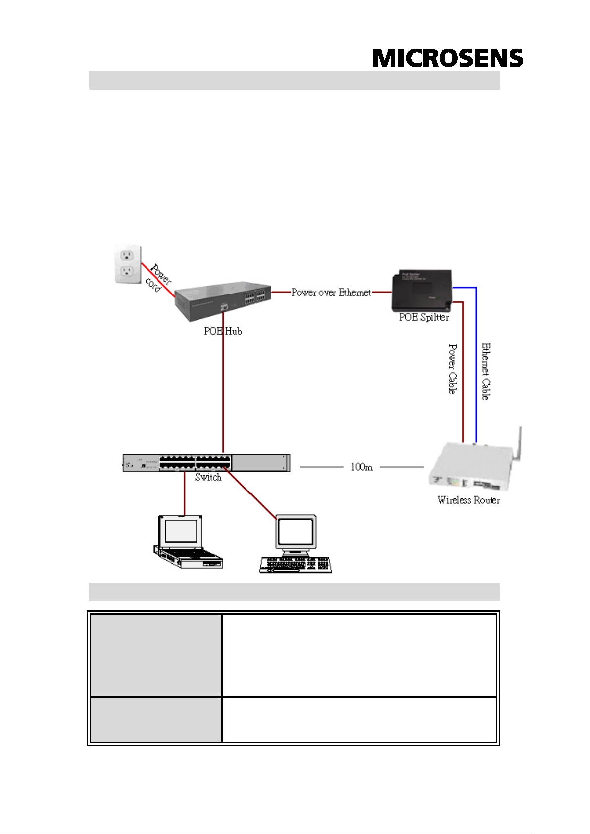
The Power over Ethernet Splitter splits data and power out, and outputs
Ethernet data and DC 5V/7.5V/9V/12V power to the network device that is
not compliant with IEEE802.3af st andard. The network device can accept
the power and Ethernet data from the Splitter. The following figure shows
how the Power over Ethernet Splitter works.
Features
Standard
Power jack diameter
IEEE802.3u 100BASE-TX
IEEE802.3ab Gigabit Ethernet
IEEE802.3af Power over Ethernet
5.5 x 2.0mm
5.5 x 2.5mm
1
Page 4

DIP 12V: Output voltage 12V
Data and power in: 1 x RJ-45,
m feeding
10BASE-T: 2-pair UTP/STP Cat.3, 4,5 cable
Operating
0oC ~ 45oC,
Storage
EMI & Safety
CE, CE/EN60950-1
Power Consumption
DIP
Connector
10W
DIP 9V: Output voltage 9V
DIP 7.5V: Output voltage 7.5V
DIP 5V: Output voltage 5V(Default)
Data pin 1,2,3,6,4,5,7,8
Power pin: 4,5(V+), 7,8(V-)
or 1,2(V+), 3,6(V-)
Data out: 1 x RJ-45, Data pin 1,2,3,6,4,5,7,8
Power out: 5V, 7.5V, 9V, 12V (Maximu
current: 2.0A@5V)
EIA/TIA-568 100-ohm (100m)
100BASE-TX: 2-pair UTP/STP Cat.5 cable
Network Cable
EIA/TIA-568 100-ohm (100m)
1000Base-T: 4-pair UTP/STP Cat. 5e cable
EIA/TIA-568 100-ohm (100m)
LED
environment
Power (green)
10% ~ 90% Humidity (non-condensing)
-40oC~ 70oC
Temperature
Dimension
80mm x 55mm x 26mm (W x D x H)
The ITE is to be connected only to PoE networks without routing to the
outside plant.
2
Page 5

Hardware Description
The Power over Ethernet Splitter has three connection ports, one LED
indicator, and DIP switch for voltage adjust. We will describe each part as
follows.
Data In port: It is an RJ-45 Ethernet interface port for data transmit
into the PoE Splitter. It is for connecting with PoE injector or PoE
switch.
The Data In port figure
Data Out port: It is an RJ-45 Ethernet port and has a fix RJ-45 cable
to connect with the network to PD.
Power Out port: It supports two types of power cable—5.5 x 2.0mm
and 5.5 x 2.5mm. These two types of DC power jack are contained in
package. The Power Out port is for transmitting the power to the PD.
Data Out and Power Out port figure
LED indicator: one Power LED indictor for the system unit. It locates
on the topside of the Power over Ethernet Splitter.
System power LED indicator
3
Page 6

DIP switch: It is used for switching the voltage which supplies to PD.
It provides four voltage output options–5V, 7.5V, 9V and 12V. When
you adjust the DIP switch, please power off the Power over Ethernet
Splitter.
DIP Switch
Package Contents
One Power over Ethernet Splitter
2 DC Power Jack—5.5 x 2.0mm and 5.5 x 2.5mm
User Manual
Compare the contents of your Power over Ethernet Splitter package with
the standard checklist above. IF any item is missing or damaged, please
contact your local dealer for service.
Installation
To install the Power over Ethernet Splitter, please follow the steps as
follows.
1. Connect the side of RJ-45 cable to DATA IN port on the Power over
Ethernet Splitter, and connect another side with the PoE Switc h/HUB
(which is Data out equipment). If the Switch/HUB does not support
PoE function, you need to install a PoE injector between Switch /HUB
and Power over Ethernet Splitter.
2. Use RJ-45 cable t hat i s on the Data out port in Power over Ethernet
Splitter to connect with the PD (Such as Router, Access Point…etc.)
3. Choose the power cable (Internal Diameter 2.0mm or 2.5mm) and plug
into the Power out port on the Power over Ethernet Splitter.
4
Page 7

4. Plug in the power cable of the Power over Ethernet Splitter to the PD’s
power plug.
5. Adjust the Voltage for PD; switch the DIP setting on the Power over
Ethernet Splitter. It supports four sorts of voltage output–5V, 7.5V, 9V
and 12V. The default value will be set on 5V. When you change
voltage by DIP, the Power over Ethernet Splitter must be in powered
off status.
6. Before starting, make sure all connections are correct and the output
voltage is set in the right position.
The Power over Ethernet Splitter connects to the Switch or PoE
Hub via Data in port.
The Power over Ethernet Splitter connect to the PD has two
connections – Data out and Power out.
The voltage has four options–5V, 7.5V, 9V and 12V.
5
 Loading...