

Page 1

Power Over Ethernet Splitter
with adjustable output
User Manual
MS400940
Page 2

Content
Overview ............................................................ 1
Features ............................................................. 1
Hardware Description ...................................... 3
Package Contents ............................................ 4
Installation ......................................................... 5
Page 3
POE Hub
Power over Ethernet
1 2 3 4 5 6
7 8 9101112
A
B
12x
6x
8x2x9x3x10x4x11x
5x
7x
1x
Ethernet
A
12x
6x
8x2x9x3x10x4x11x
5x
7x
1x
C
Switch
POE Spiltter
Wireless Router
Power Cable
Ethernet Cable
P
o
w
e
r
co
r
d
100m
Standard
IEEE802.3 10BASE-T
IEEE802.3u 100BASE-TX
IEEE802.3af Power over Ethernet
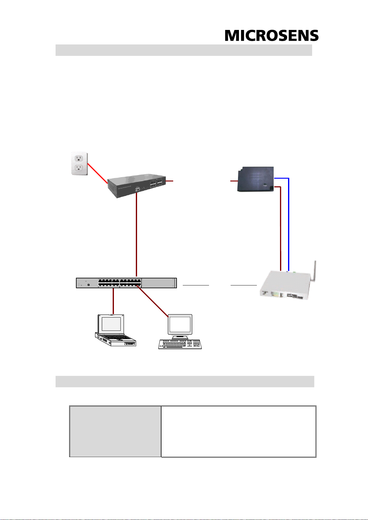
Overview
The Power over Ethernet Splitter split data and power out, and output
Ethernet data and DC power to the network device that is not compliant
with IEEE802.3af standard. The network device can accept the power and
Ethernet data from the Splitter. The following figure shows the how Power
over Ethernet Splitter work.
Features
1
Page 4

Power jack diameter
2 power cable with straight plug and a right
angle plug
Plug dimension: 5.5 x 2.0mm, 5.5 x 2.5mm
Adjust Switch
4-Segment switch for output voltage
selection
Connector
Data and power in: 1 x RJ-45.Data pin
1,2,3,6
Power pin: 4,5(V+), 7,8(V-) and 1,2(V+),
3,6(V-)
Data out: 1 x RJ-45, Data pin 1,2,3,6
Power out jack: 5V, 7.5V, 9V, 12V
(Adjustable)/ Maximum feeding current:
2.0A@5V
Network Cable
10BASE-T: 2-pair UTP/STP Cat.3, 4,5 cable
EIA/TIA-568 100-ohm (100m)
100BASE-TX: 2-pair UTP/STP Cat.5 cable
EIA/TIA-568 100-ohm (100m)
LED
System: power (green)
Power Input
DC 48V, 0.3A
Operating Temperature
0℃~45℃
Operating Humidity
10%~90% Humidity (non-condensing)
Storage Temperature
-40℃~70℃
Dimension
80mm x 55mm x 26mm (W x D x H)
EMI & Safety
CE, CE/EN60950
The ITE is to be connected only to PoE networks without routing to the
2
Page 5

outside plant.
Hardware Description
The Power over Ethernet Splitter has three connection ports, one LED
indicator, and Dipswitch for voltage adjusting. We will description each in
following.
Data In port: It is a RJ-45 Ethernet interface port for data transmit to
the PoE Splitter. It is for connecting with PoE injector.
The Data In port figure
Data Out port: It is a RJ-45 Ethernet port and has a fix RJ-45 cable for
connecting with the Power device.
Power Out port: It supports two types of power cable – 5.5 x2.0mm
and 5.5x2.5mm. These two types of DC power jack contain in package.
The Power Out port is for transmitting the power to the device that
powered by 5V, 7.5V, 9V or 12V.
Data Out and Power Out port figure
LED indicator: one Power LED indictor for the system unit. It locates
on the topside of the Power over Ethernet Splitter.
3
Page 6

System power LED indicator
DIPswitch: It uses for switching the voltage to PD. It provides
four-voltage value – 5V, 7.5V, 9V and 12V. The default is 5V. When
you adjust the Dipswitch, please power off the Power over Ethernet
Splitter.
DIPswitch
Package Contents
One Power over Ethernet Splitter with fixed RJ-45 cable(315 mm)
2 DC Power Jack – inner dimension: 5.5x2.0mm x 1, length: 914
mm(3Ft) / 5.5x2.5mm x 1, length: 914mm(3Ft)
User Manual
Compare the contents of your Power over Ethernet Splitter package with
the standard checklist above. If any item is missing or damaged, please
contact your local dealer for service.
4
Page 7

Installation
To install the Power over Ethernet Splitter, please follow the below steps.
1. Using RJ-45 cable to connect the Data in port on the Power over
Ethernet Splitter with the PoE Switch/HUB (which is Data out port). If
the Switch/HUB does not support PoE function, you need to install a
PoE injector between Switch/HUB and Power over Ethernet Splitter.
2. Using RJ-45 cable to connect the Data out port on the Power over
Ethernet Splitter with the PD (Such as Router, Access Point…etc.)
3. Choose the power cable (Internal Diameter 2.0mm or 2.5mm) and plug
into the Power out port on the Power over Ethernet Splitter.
4. Plug in the power cable of the Power over Ethernet Splitter to the PD’s
power plug.
5. Adjust the Voltage for PD; switch the DIP setting on the Power over
Ethernet Splitter. It supports four type of voltage – 5V, 7.5V, 9V and
12V. The default value will be set on 5V. When you change voltage
by DIP switching to different voltage, the Power over Ethernet Splitter
must be in powered off status.
6. Before starting, make sure all connections are correct and the voltage is
right.
The Power over Ethernet Splitter connects to the Switch or POE
Injector is in Data in port.
The Power over Ethernet Splitter connects to the device with two
connection ports – Data out and Power out.
The voltage has four types – 5V, 7.5V, 9V and 12V.
5
 Loading...