

Page 1

Gigabit Ethernet Converter
User's Manual
1000Base-T to 1000Base-X Fiber Converter
Release 1.0
i
Page 2

Page 3

Caution
Circuit devices are sensitive to stat i c electricity, which can damage their
delicate electronics. Dry weather conditions o r walking across a carpeted floor may
cause you to acquire a static electri cal charge.
To protect your devi ce, always:
• Touch the metal chassis of your computer to ground the static electrical charge
before you pick up the circuit device.
• Pick up the device by holding it on the left and ri ght edges only.
Electronic Emission Notices
European Community (CE) Electromagnetic Compatibility Directive
This equipment has been tested and found to comply with the protection
requirements of European Emission Sta ndard EN55022/EN60555-2 and the
Generic European Immunity Standard EN50082-1.
EMC:
EN55022(1988)/CISPR-22(1985) class A
EN60555-2(1995) class A
EN60555-3
IEC1000-4-2(1995) 4K V CD, 8KV, AD
IEC1000-4-3(1995) 3V/m
IEC1000-4-4(1995) 1KV – (power line), 0.5KV – (signal line)
1
Page 4

FX TP
LINK
FDX
PWR
TX RX
Fig. 1 1000Mbps TP-to-Fiber Converter Front Panel
1.Introduction
1-1. Overview
IEEE802.3z/AB 1000Mbps Gigabit Ethernet converter supports two
types of media for network connection such as 1000Base-T and
1000Base-SX/LX. The media converter is used to convert one type
media signal to other type equivalent that allows two type segments
connect easily and inexpensively. The converter can be used as a
standalone unit or as a slide-in module to the 19" converter rack (up
to 12 units) for use at a central wiring closet, or mounted on DIN-Rail
with a DIN-Rail kit for industrial application. The media converter has
commercial and industrial different operating temperature optional
specifications.
1-2. Checklist
Before you start installing the Converter, verify that the package
contains the following:
The TP-Fiber Converter
AC-DC Power Adapter
This User's Manual
Please notify your sales representative immediately if any of the
aforementioned items is missing or damaged.
1-3. View of converter
2
Page 5
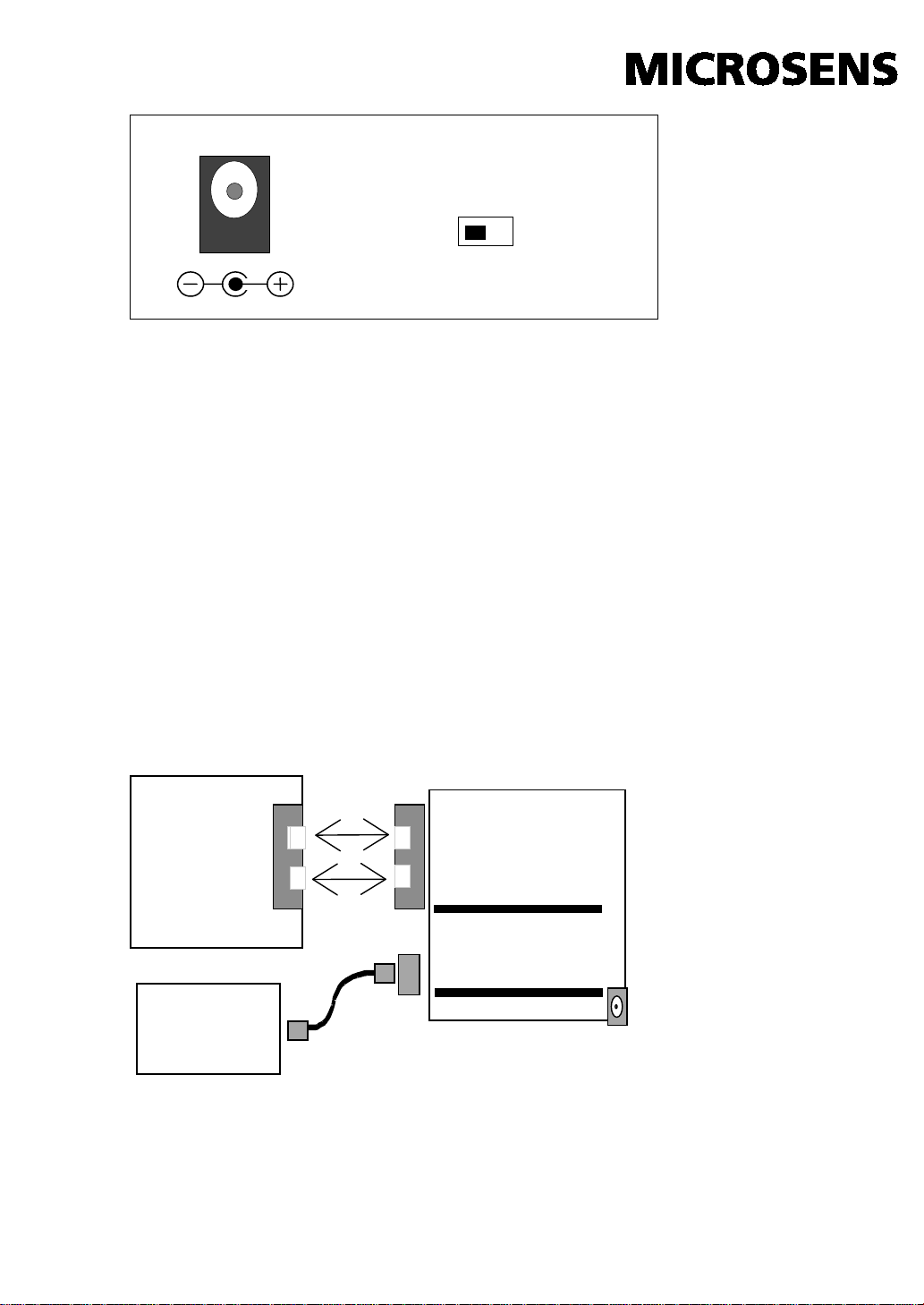
5VDC
FIBER MODE
1000SX/LX
TX
RX
TP-to-1000SX/LX
Fig. 2 1000Mbps TP- to- Fiber Converter Rear Panel
AUTO FORCE
Note: “Auto” means fiber in auto negotiation mode;
“Force” means fiber in force mode
2. Installation
2-1 Installing the Fiber converter
Verify the AC-DC adapter conforms to your country AC power
requirement and insert the power plug
Install the media cable for network connection
2-2 Connection
Fiber
Network
1000Base-T
Network
RX
TX
Converter
3
Page 6
Attach TP Cat. 5 cable to TP port
The 1000 TP port is transmit/receive wires
wiring and the Link LED status
Attach the fiber cable. The Tx, Rx fiber cable
must be paired at both ends
Converter
TP Port
1000FDX with NWay flow control
00FDX with NWay flow
control
Lit when fiber connection is good
Blinks when fiber data is receiving
FX FDX
Green
Lit when fiber full-duplex mode is active
TP LINK
Green
Lit when TP connection is good
TP FDX
Green
Lit when TP full-duplex mode is active
TP ACT
Green
Blinks when TP data is receiving
PWR
Green
Lit when +5V power is coming up
DC Jack : 2.5mm
TP Port
Fiber Port
auto-link (e.g. either MDI-X or MDI-II). It will
auto-cross-connect transmit/receive wires to a
switch or to a workstation, be sure the proper
1000FDX with NWay flow control
Converter
Fiber Port
Link partner must be 10
Warning:
The converter TP 1000FDX NWay port must be connected to a
NWay TP device. When Converter TP Port (NWay) connecting to
a non_NWay 1000FDX TP partner, it could not inter-operate
properly between local and remote TP partners.
Ensure all network nodes are configured at an identical operation
mode. Improper operation and flow control mode between TP and
Fiber port connections will render the LAN to work poorly.
2-3 LED Description
LED Color Function
FX LINK Green
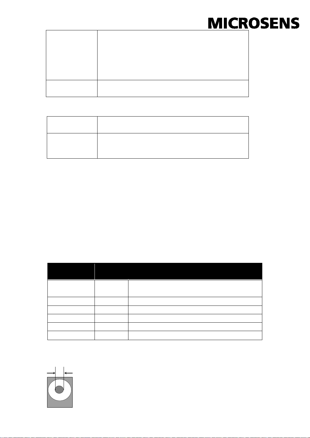
2-4. DC Jack and AC-DC Power Adapter
The DC jack's central post is 2.5mm wide
DC Input : +5V
(Converter DC Current Consumption: 1A when
operation at full speed/load)
4
Page 7

Multi-Mode Fiber
62.5/125µm
Multi-Mode Fiber
50/125µm
MHz-Km
MHz-Km
1000SX
850nm
160
220m
400
500m
200
275m
500
550m
2-5 Cable Parameter
• TP Cable Limitations: Cat. 5 and up to 100m
• Fiber Cable Limitations:
1000LX
1310nm
Note: 850nm, 1310nm ,1550nm is the wavelength of fiber transceiver
Bandwidth
Single-Mode Fiber 9/125µm is up to 10km
Distance
Bandwidth
Distance
3. Technical Specifications
• Standards :IEEE802.3z/ AB 1000 Base-T,
1000Base-SX/LX
• UTP Cable :Cat. 5 cable and up to 100m
Fiber Cable :
1000SX: 50/125, 62.5/125, or 100/140µm multi-mode
1000LX: 8.3/125, 8.7/125, 9/125 or 10/125µm single-mode
• LED Indicators :
PWR
FX LINK, FDX, TP LINK, ACT
• Data Transfer Rate:
2000Mbps/full-duplex
• TP Flow Control : Nway auto-negotiation
Fiber Flow Control : Nway at full-duplex mode
• Power Requirement : 1A @+5VDC above AC-DC Adapter
-10° to 60°C
• Ambient Temperature : -10° to 60°C
• Humidity : 5% to 90%
• Dimensions : 26.2(H) × 70.3(W) × 94(D) mm (Fig. 7)
Note: For connecting this device to Router, Bridge, or Switch,
please refer to the corresponding device's Technical
Manual.
5
Page 8

Fig. 7 Dimension Diagram
6
 Loading...