

Page 1

MICROSENS
Ethernet / Fast Ethernet
Twin Bridge module
Description
Fast Ethernet Bridge
The bridge enables connection of copper and fiber segments to Ethernet and Fast
Ethernet whilst at the same time altering the speed. The new twin bridge achieves a
higher port density in the distribution equipment by integrating two bridges per card.
Redundancy
When the card is configured correctly, the two bridges can be switched to one bridge
for redundant connections. This means that important connections can be secured using
this module without the need for such costly features as spanning trees. Two routes are
possible via both, fiber and copper. Switching occurs physically by recognizing links.
4 Port Switch
The card function has a further setting that permits the connections to be grouped into
a 4-port switch with two fiber ports (100Base-FX) and two copper ports (10/100Base-TX).
This switch makes it extremely easy to implement service networks, e.g. for coupling
management agents or rack monitoring systems in existing connections.
Bandwidth limitation
An additional operating mode allows the card to be configured as a fiber/ fiber bridge
with the option of limiting bandwidth. Service providers can use this to release data
rates to customers in a targeted way. If the customer is not prepared to pay for the
maximum bandwidth or if a lower performance is sufficient they can make a targeted
reduction. If migrations are completed later the required bandwidth of up to 100 Mbit/s
is released by reconfiguration, it is not necessary to swap out the hardware. The copper
connections can also be used as mirroring interfaces at the same time, e.g. for sniffer
analyses.
In addition to multimode versions, MICROSENS also offers single mode bridges with
altered optical parameters, which enable long-range segment links of up to 125 km.
These single mode designs are used in particular for Fiber To The Home (FTTH) projects.
The end user can obtain internet services, video on demand and VoIP applications using
the familiar 10/100Base-TX copper connection.
The configuration of the features can be done by the network management or the
integrated configuration switches.
MICROSENS GmbH & Co. KG - Kueferstr. 16 - D-59067 Hamm / Germany - Tel. +49 (0)2381/9452-0 - Fax -100 - www.microsens.com
Page 2

Multifunctional Bridge 10/100Base-TX/100Base-FX Page 2/8
Technical Specifications
Type 2 Port Fast Ethernet Bridge For the coupling of Ethernet and
Fast Ethernet segments for the installation in the
MICROSENS modular chassis
Fiber type Multimode 50 or 62,5/125µm
optional single mode 9/125µm duplex
Opt. output power -19 dBm (1300 nm Multimode min.)
-15 dBm (1300 nm single mode min., 15 km version)
-5 dBm (1300 nm single mode min., 40 km version)
-5 dBm (1550 nm single mode min., 80 km version)
0 dBm (1550 nm single mode min., 125 km version)
Opt. sensitivity -31 dBm (1300 nm Multimode)
-31 dBm (1300 nm single mode, 15 km version)
-34 dBm (1300 nm single mode, 40 km version)
-34 dBm (1550 nm single mode, 80 km version)
-37 dBm (1550 nm single mode, 125 km version)
Max. distance Full duplex: 2 km (Multimode),
15..125 km (Single mode),
Half duplex: 412 m
Cable type Shielded Twisted Pair cable, 100 Ohm, Category 5
Data rate 10 or 100 Mbit/s
Max. distance 100 m
Configuration 10/100Base-TX: Autonegotiation, Auto Crossing
100Base-FX: manual per DIP-switch
LED displays PWR ready for operation
TX1 first Twisted Pair-connection
FX1 first fiber connection
TX2 second Twisted Pair-connection
FX2 second fiber connection
Power supply 12 V DC / max. 500 mA via backplane
Operating- /Stor.temp. 0°C to 55°C / -20°C to 80°C
Rel. humidity 5% to 80% non condensing
Dimensions 3 HE x 6 TE (128 x 31 mm)
Management Status monitoring and configuration via SNMP/web based
management with management module MS416020
Configuration Hardware level per DIP-switch (DIP-switch 13: off)
per Management (DIP-switch 13: on)
MICROSENS GmbH & Co. KG - Kueferstr. 16 - D-59067 Hamm / Germany - Tel. +49 (0)2381/9452-0 - Fax -100 - www.microsens.com
Page 3
Multifunctional Bridge 10/100Base-TX/100Base-FX Page 3/8
s
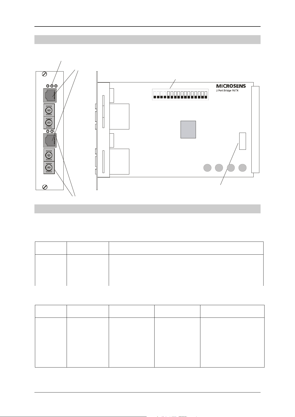
Construction
LED-display
10/100Base-TX ports
TX1 FX1 PWR
Tx
Rx
TX2
FX2
Tx
Rx
Multifunctiona l Bridge
MICROSENS
100Base-FX ports
Configuration
DIP-switch for
configuration
1
3
5
4
7
689
111012
13
151416
2
Fuse 500 mA, slow
All operation modes can be configured with the network management (with
MS416020) or the DIP switches. The selection about the configuration is done by DIP
switch 13.
Function Switch 13 Description
1 ON Configuration through management (DIP switches 1-12
and 14-16 without function)
2 OFF Configuration per DIP switches
To configure the different operating modes the module has several DIP switches. The
selection of the main functionality is done by DIP switches 14, 15 and 16:
Function Switch 14 Switch 15 Switch 16 Description
1 OFF OFF OFF Fiber-Bridge
2 OFF OFF ON 2 channel Bridge
3 OFF ON OFF Redundant Bridge
4 OFF ON ON 4 Port Switch
MICROSENS GmbH & Co. KG - Kueferstr. 16 - D-59067 Hamm / Germany - Tel. +49 (0)2381/9452-0 - Fax -100 - www.microsens.com
Page 4

Multifunctional Bridge 10/100Base-TX/100Base-FX Page 4/8
The function of the other DIP switches depends on the selected main functionality.
With changing the main functionality, the functions of the DIP switches 1-12
changes!
Function 1: Fiber-Bridge
The module is configured for the data transmission between the two fiber ports. The
twisted pair ports can be used for monitoring. Further it is possible to adjust the speed
between the fiber ports by using the management (32 kB blocks) or the integrated DIP
switches (see table below).
Following Dip switches are available for the configuration of the fiber ports:
DIP switch Function (ON/OFF)
1 ON: FX-Port 1 full duplex OFF: FX-Port 1 half duplex
2 ALM for fiber port 1
3 Link Through from fiber port 1 to 2
4 ON: FX-Port 2 full duplex OFF: FX-Port 2 half duplex
5 ALM for fiber port 2
6 Link Through from fiber port 2 to 1
7 ON: Mirroring of the data of both fiber ports on TP port 1
OFF: Mirroring FX-Port 2 on TP-Port 1 and FX-Port 4 on TP-Port 3
8 ON: Flow control activated
9 – 11 Bandwidth limitation
12 Flashing for fiber Port 2 and Port 4
The Dip switches 9 to 11 are offering the possibility for the bandwidth limitation.
Switch
9 10 11
Maximum data rate between the
Ports Fiber 2 and Fiber 4 each direction
0 0 0 100 Mbit / Sec. (100Base-TX), no limitation
0 0 1 75 Mbit / Sec.
0 1 0 50 Mbit / Sec.
0 1 1 34 Mbit / Sec. (E3)
1 0 0 20 Mbit / Sec.
1 0 1 10 Mbit / Sec. (10Base-TX)
1 1 0 8 Mbit / Sec.
1 1 1 2 Mbit / Sec. (E1)
0 = switch OFF, 1 = switch ON
MICROSENS GmbH & Co. KG - Kueferstr. 16 - D-59067 Hamm / Germany - Tel. +49 (0)2381/9452-0 - Fax -100 - www.microsens.com
Page 5

Multifunctional Bridge 10/100Base-TX/100Base-FX Page 5/8
Function 2: Two channel Bridge
The device has two independent bridging channels. The data is transmitted separately
and a cross connection between the channels is not possible.
Following DIP switches are available for the configuration of the ports:
Channel DIP switch Function (ON/OFF)
1 1 ALM for fiber port
2 Link Through from copper to fiber
3 Link Through from fiber to copper
4 ON: fiber full duplex OFF: fiber half duplex
5 ON: TP Autonegotiation OFF: TP 100 Mbit full duplex
6 Flashing for fiber port
2 7 ALM for fiber port
8 Link Through from copper to fiber
9 Link Through from fiber to copper
10 ON: fiber full duplex OFF: fiber half duplex
11 ON: TP Autonegotiation OFF: TP 100 Mbit full duplex
12 Flashing for fiber port
Function 3: Redundant Bridge
The device is working on channel 1 as a bridge. If the fiber port of channel 1 fails, the
second fiber port takes over the data transfer. The function of the copper port is the
same. The switching time to the redundant port is lower than 100 ms.
The configuration of both ports for the copper and the fiber ports are the same, so the
settings for the fiber port 1 are also valid for fiber port 2.
Following Dip switches are available for the configuration of the ports:
DIP switch Function (ON/OFF)
1 ALM for fiber port
2 Link Through from copper to fiber
3 Link Through from fiber to copper
4 ON: fiber full duplex OFF: fiber half duplex
5 ON: TP Autonegotiation OFF: TP 100 Mbit full duplex
6, 7 Reserved
8 ON: Flow control on OFF: Flow control off
9-11 Bandwidth limitation (see fiber bridge)
MICROSENS GmbH & Co. KG - Kueferstr. 16 - D-59067 Hamm / Germany - Tel. +49 (0)2381/9452-0 - Fax -100 - www.microsens.com
Page 6

Multifunctional Bridge 10/100Base-TX/100Base-FX Page 6/8
N
F
Function 4: 4 Port Switch
The device is working as a standard 4 port switch. In this mode the device has two
10/100Base-TX and two 100Base-FX ports. All ports are having the same priority. The
switch is “outband managed” with the integrated management features for the rack
chassis.
Following Dip switches are available for the configuration of the ports:
DIP switch Port Function (ON/OFF)
1 1 (TP) ON: Autonegotiation OFF 100Mbit, full duplex
2 2 (FX) ON: full duplex OFF: half duplex
3 3 (TP) ON: Autonegotiation OFF 100Mbit, full duplex
4 4 (FX) ON: full duplex OFF: half duplex
5 Link Through from port 2 to 4 (fiber)
6 Link Through from port 4 to 2 (fiber)
7 2 (FX) ALM for fiber port 2
8 4 (FX) ALM for fiber port 4
9 2, 4 (FX) Flashing for both fiber ports
10– 12 Reserved
Link Trough / ALM
The link status of each segment is forwarded, that means in case of a missing link on
one side, the link on the corresponding side is also switched (physically) off .
Attention: In idle state (no cables connected) there are no link signals send by the
bridge. This is no malfunction.
Port x Port x
RX RXTX TX
TX TXRX RX
Port y Port y
Link Throug h ON Link Throu gh OFF
With activated ALM (Advanced Link Monitoring) the same port, which does not receive
a link signal, is also not sending an output link signal (loop back). This ensures that both
directions (transmit and receive) of the channel are having the same link status.
No Li nk Link
Port x Port x
No Link Link
TX TX
RX RX
Port y Po rt y
ALM O
MICROSENS GmbH & Co. KG - Kueferstr. 16 - D-59067 Hamm / Germany - Tel. +49 (0)2381/9452-0 - Fax -100 - www.microsens.com
ALM OF
Page 7

Multifunctional Bridge 10/100Base-TX/100Base-FX Page 7/8
Operation
The module is designed for the mounting into a MICROSENS modular chassis. It can be
combined with all other converter modules of the same series.
The power supply is done by a central power supply unit via the backplane of the
chassis. Together with the power supply it is possible to insert to insert up to 12
modules into the 3 U chassis. Optional it is possible to insert a second redundant power
supply. In this case it is possible to use up to 10 converter modules.
Beside the 3 U chassis there is an additional 1 U chassis (horizontal slots) available. This
chassis has an integrated power supply (MS416006), which can be also redundant
(MS416007).
Furthermore there are in addition to the 19” racks, desktop chassis for one (MS417001)
or two (MS417041) modules available. With the wall bracket (MS417001-WH) it is
possible to mount the desktop chassis on the wall.
Management
The module can be configured and monitored by the central management agent. There
are two different modes possible:
DIP-13 off Monitoring of the actual configuration and operation states,
configuration through the NMS is not possible.
DIP-13 on Monitoring with Network management (SNMP- and web based),
configuration by web management, terminal or telnet connection.
The SNMP and web based management features of the system are provided by the
management master module (MS416020). When choosing the management features it
is necessary that the chassis (e.g. MS416001M) and the power supply (MS416004M) are
also supporting the management.
Visualising - and
3 U chassis MS416001
Power supplies MS416004M (redundant)
configurationexample with an SNMP
management platform:
Twin bridge manageable (e.g. MS416360M)
MICROSENS GmbH & Co. KG - Kueferstr. 16 - D-59067 Hamm / Germany - Tel. +49 (0)2381/9452-0 - Fax -100 - www.microsens.com
Page 8

Multifunctional Bridge 10/100Base-TX/100Base-FX Page 8/8
To access the data of the modules via SNMP it is necessary to integrate the structure of
the MIB into the existing network management. The MICROSENENS MIB file can be
downloaded from the web based management of module. The MIB file is in ASCII
format.
The configuration of the network management is protected by a password. The
following values are default from the factory.
Console: Read only Console: Admin WEB: Configuration
Username user admin
Password microsens microsens microsens
The password for the web based configuration is the same as the administrator
password of the console and can be changed together with it.
Safety Notes
WARNING: Infrared radiation as used for data transmission within the fiber optic,
although invisible to the human eye, can nevertheless cause damage.
To avoid damage to the eyes:
• never look straight into the output of fiber optic components – danger of
blinding!
• cover all unused optical connections with caps.
• commission the transmission link only after completing all connections.
The active laser components used with this product comply with the provisions of Laser
Class 1.
Order Information
Art.-No. Description Connectors
MS416360M Twin Bridge Module, 10/100Base-TX/100Base-FX
1300nm Multimode ST
MS416361M Twin Bridge Module, 10/100Base-TX/100Base-FX
1300nm Multimode SC
MS416362M Twin Bridge Module, 10/100Base-TX/100Base-FX
1300nm Single mode Laser min. 15 km, SC
MS416363M Twin Bridge Module, 10/100Base-TX/100Base-FX
1300nm Single mode Laser min. 15 km, ST
MS416364M Twin Bridge Module, 10/100Base-TX/100Base-FX
1300nm Single mode Laser min. 40 km, SC
MS416368M Twin Bridge Module, 10/100Base-TX/100Base-FX
1300nm Multimode MT-RJ
MICROSENS reserves the right to make any changes without further notice to any product to improve reliability, function
or design. MICROSENS does not assume any liability arising out of the application or use of any product. 2903/He
2x RJ-45 10/100TX
4x ST 100Base-FX
2x RJ-45 10/100TX
2x SC 100Base-FX
2x RJ-45 10/100TX
2x SC 100Base-FX
2x RJ-45 10/100TX
4x ST 100Base-FX
2x RJ-45 10/100TX
2x SC 100Base-FX
2x RJ-45 10/100TX
2x MT-RJ 100Base-FX
MICROSENS GmbH & Co. KG - Kueferstr. 16 - D-59067 Hamm / Germany - Tel. +49 (0)2381/9452-0 - Fax -100 - www.microsens.com
 Loading...