

Page 1

.................SyncServerS600
.................SyncServerS650
..................
...................User’sGuide
...................RevisionD1February,2018
...................PartNumber:098‐00720‐000
User’s Guide updates are available at: www.microsemi.com/ftdsupport
Page 2

©2018MicrosemiAllrightsreserved.PrintedinU.S.A.
Allproductnames,servicemarks,trademarks,andregisteredtrademarksusedinthisdocumentarethepropertyoftheirrespectiveowners.
Page 3

Table of Contents
Purpose of This Guide . . . . . . . . . . . . . . . . . . . . . . . . . . . . . . . . . . . . . . . . . . .20
Who Should Read This Guide. . . . . . . . . . . . . . . . . . . . . . . . . . . . . . . . . . . . . .20
Structure of This Guide . . . . . . . . . . . . . . . . . . . . . . . . . . . . . . . . . . . . . . . . . . .20
Conventions Used in This Guide. . . . . . . . . . . . . . . . . . . . . . . . . . . . . . . . . . . .22
Warnings, Cautions, Recommendations, and Notes . . . . . . . . . . . . . . . . . . . .23
Where to Find Answers to Product and Document Questions . . . . . . . . . . . . .24
What’s New In This Guide. . . . . . . . . . . . . . . . . . . . . . . . . . . . . . . . . . . . . . . . .24
Related Documents and Information. . . . . . . . . . . . . . . . . . . . . . . . . . . . . . . . .26
Chapter 1 Overview
Overview . . . . . . . . . . . . . . . . . . . . . . . . . . . . . . . . . . . . . . . . . . . . . . . . . . . . . .28
SyncServer S600 . . . . . . . . . . . . . . . . . . . . . . . . . . . . . . . . . . . . . . . . . . .28
SyncServer S650 . . . . . . . . . . . . . . . . . . . . . . . . . . . . . . . . . . . . . . . . . . .28
SyncServer S650i . . . . . . . . . . . . . . . . . . . . . . . . . . . . . . . . . . . . . . . . . . .28
SyncServer S6x0 Key Features . . . . . . . . . . . . . . . . . . . . . . . . . . . . . . . .28
Software Options . . . . . . . . . . . . . . . . . . . . . . . . . . . . . . . . . . . . . . . . . . .29
Security Features . . . . . . . . . . . . . . . . . . . . . . . . . . . . . . . . . . . . . . . . . . .30
Physical Description . . . . . . . . . . . . . . . . . . . . . . . . . . . . . . . . . . . . . . . . . . . . .30
Communications Connections . . . . . . . . . . . . . . . . . . . . . . . . . . . . . . . . .35
Input Connections . . . . . . . . . . . . . . . . . . . . . . . . . . . . . . . . . . . . . . . . . . .36
Output Connections . . . . . . . . . . . . . . . . . . . . . . . . . . . . . . . . . . . . . . . . .37
Alarm Relay . . . . . . . . . . . . . . . . . . . . . . . . . . . . . . . . . . . . . . . . . . . . . . .38
Timing I/O Card Connections . . . . . . . . . . . . . . . . . . . . . . . . . . . . . . . . . .38
Low Phase Noise (LPN) Module Connections . . . . . . . . . . . . . . . . . . . . .39
Power and Ground Connections. . . . . . . . . . . . . . . . . . . . . . . . . . . . . . . .40
Functional Description. . . . . . . . . . . . . . . . . . . . . . . . . . . . . . . . . . . . . . . . . . . .41
LEDs . . . . . . . . . . . . . . . . . . . . . . . . . . . . . .
. . . . . . . . . . . . . . . . . . . . . . .42
Communication Ports . . . . . . . . . . . . . . . . . . . . . . . . . . . . . . . . . . . . . . . .42
Time Inputs . . . . . . . . . . . . . . . . . . . . . . . . . . . . . . . . . . . . . . . . . . . . . . . .43
Frequency Inputs . . . . . . . . . . . . . . . . . . . . . . . . . . . . . . . . . . . . . . . . . . .43
Frequency and Timing Outputs. . . . . . . . . . . . . . . . . . . . . . . . . . . . . . . . .43
Configuration Management. . . . . . . . . . . . . . . . . . . . . . . . . . . . . . . . . . . . . . . .44
Keypad/Display Interface . . . . . . . . . . . . . . . . . . . . . . . . . . . . . . . . . . . . .44
Web Interface . . . . . . . . . . . . . . . . . . . . . . . . . . . . . . . . . . . . . . . . . . . . . .44
Command Line Interface (CLI) . . . . . . . . . . . . . . . . . . . . . . . . . . . . . . . . .45
Alarms. . . . . . . . . . . . . . . . . . . . . . . . . . . . . . . . . . . . . . . . . . . . . . . . . . . . . . . .45
098-00720-000 Revision D1 – February, 2018 SyncServer 600 Series User’s Guide 3
Page 4

Table of Contents
Chapter 2 Installing
Getting Started . . . . . . . . . . . . . . . . . . . . . . . . . . . . . . . . . . . . . . . . . . . . . . . . .48
Security Considerations for SyncServer S6x0 Installation . . . . . . . . . . . .48
Site Survey . . . . . . . . . . . . . . . . . . . . . . . . . . . . . . . . . . . . . . . . . . . . . . . .48
Installation Tools and Equipment . . . . . . . . . . . . . . . . . . . . . . . . . . . . . . .49
Unpacking the Unit . . . . . . . . . . . . . . . . . . . . . . . . . . . . . . . . . . . . . . . . . . . . . .49
Rack Mounting the SyncServer S6x0 . . . . . . . . . . . . . . . . . . . . . . . . . . . . . . . .50
Making Ground and Power Connections . . . . . . . . . . . . . . . . . . . . . . . . . . . . .52
Ground Connections . . . . . . . . . . . . . . . . . . . . . . . . . . . . . . . . . . . . . . . . .52
AC Power Connection. . . . . . . . . . . . . . . . . . . . . . . . . . . . . . . . . . . . . . . .54
DC Power Connection . . . . . . . . . . . . . . . . . . . . . . . . . . . . . . . . . . . . . . .54
Signal Connections . . . . . . . . . . . . . . . . . . . . . . . . . . . . . . . . . . . . . . . . . . . . . .55
Communications Connections . . . . . . . . . . . . . . . . . . . . . . . . . . . . . . . . .55
SyncServer S6x0 Synchronization and Timing Connections . . . . . . . . . .57
Ethernet Connections . . . . . . . . . . . . . . . . . . . . . . . . . . . . . . . . . . . . . . . .57
10 GbE Connections. . . . . . . . . . . . . . . . . . . . . . . . . . . . . . . . . . . . . . . . .58
Timing I/O Module Connections . . . . . . . . . . . . . . . . . . . . . . . . . . . . . . . .59
LPN Module Connections . . . . . . . . . . . . . . . . . . . . . . . . . . . . . . . . . . . . .60
Connecting the GNSS Antenna . . . . . . . . . . . . . . . . . . . . . . . . . . . . . . . . . . . .61
Connecting Alarm Relay . . . . . . . . . . . . . . . . . . . . . . . . . . . . . . . . . . . . . . . . . .62
Installation Check List . . . . . . . . . . . . . . . . . . . . . . . . . . . . . . . . . . . . . . . . . . . .62
Applying Power to the SyncServer S6x0 . . . . . . . . . . . . . . . . . . . . . . . . . . . . .63
Normal Power Up Indications . . . . . . . . . . . . . . . . . . . . . . . . . . . . . . . . . .63
Chapter 3 Keypad / Display Interface
Overview . . . . . . . . . . . . . . . . . . . . . . . . . . . . . . . . . . . . . . . . . . . . . . . . . . . . . .65
TIME Button . . . . . . . . . . . . . . . . . . . . . . . . . . . . . . . . . . . . . . . . . . . . . . . . . . .66
STATUS Button. . . . . . . . . . . . . . . . . . . . . . . . . . . . . . . . . . . . . . . . . . . . . . . . .66
NTP Status Screen . . . . . . . . . . . . . . . . . . . . . . . . . . . . . . . . . . . . . . . . . .67
Alarm Status Screen . . . . . . . . . . . . . . . . . . . . . . . . . . . . . . . . . . . . . . . . .67
LAN Status Screens . . . . . . . . . . . . . . . . . . . . . . . . . . . . . . . . . . . . . . . . .67
Clock Status Screen . . . . . . . . . . . . . . . . . . . . . . . . . . . . . . . . . . . . . . . . .68
GNSS Receiver Status Screen . . . . . . . . . . . . . . . . . . . . . . . . . . . . . . . . .68
SyncServer Status Screen . . . . . . . . . . . . . . . . . . . . . . . . . . . . . . . . . . . .68
Option Slot A/B Status Screens . . . . . . . . . . . . . . . . . . . . . . . . . . . . . . . .68
4 SyncServer 600 Series User’s Guide 098-00720-000 Revision D1 – February, 2018
Page 5

Table of Contents
MENU Button . . . . . . . . . . . . . . . . . . . . . . . . . . . . . . . . . . . . . . . . . . . . . . . . . .69
LAN1 . . . . . . . . . . . . . . . . . . . . . . . . . . . . . . . . . . . . . . . . . . . . . . . . . . . . .69
Display . . . . . . . . . . . . . . . . . . . . . . . . . . . . . . . . . . . . . . . . . . . . . . . . . . .70
Sys Control . . . . . . . . . . . . . . . . . . . . . . . . . . . . . . . . . . . . . . . . . . . . . . . .71
Keypad . . . . . . . . . . . . . . . . . . . . . . . . . . . . . . . . . . . . . . . . . . . . . . . . . . .72
Chapter 4 Web Interface
System Information . . . . . . . . . . . . . . . . . . . . . . . . . . . . . . . . . . . . . . . . . . . . . .74
Status / Information Windows . . . . . . . . . . . . . . . . . . . . . . . . . . . . . . . . . . . . . .75
Timing Status & Information . . . . . . . . . . . . . . . . . . . . . . . . . . . . . . . . . . .76
GNSS Status & Information . . . . . . . . . . . . . . . . . . . . . . . . . . . . . . . . . . .82
Network Status & Information . . . . . . . . . . . . . . . . . . . . . . . . . . . . . . . . . .83
NTP Status & Information . . . . . . . . . . . . . . . . . . . . . . . . . . . . . . . . . . . . .84
Timing Services Information . . . . . . . . . . . . . . . . . . . . . . . . . . . . . . . . . . .84
Timing Services Status . . . . . . . . . . . . . . . . . . . . . . . . . . . . . . . . . . . . . . .84
Alarm Information . . . . . . . . . . . . . . . . . . . . . . . . . . . . . . . . . . . . . . . . . . .85
Slot Modules Status & Information . . . . . . . . . . . . . . . . . . . . . . . . . . . . . .85
“About” Device Information . . . . . . . . . . . . . . . . . . . . . . . . . . . . . . . . . . . .85
Navigation Windows . . . . . . . . . . . . . . . . . . . . . . . . . . . . . . . . . . . . . . . . . . . . .86
Network Configuration Windows. . . . . . . . . . . . . . . . . . . . . . . . . . . . . . . .88
Network Timing Windows . . . . . . . . . . . . . . . . . . . . . . . . . . . . . . . . . . . . .93
Timing Configuration Windows . . . . . . . . . . . . . . . . . . . . . . . . . . . . . . . .111
1PPS Time Interval Measurement . . . . . . . . . . . . . . . . . . . . . . . . . . . . .114
References Configuration Window . . . . . . . . . . . . . . . . . . . . . . . . . . . . .116
Security Configuration Windows . . . . . . . . . . . . . . . . . . . . . . . . . . . . . . .118
Admin Configuration Windows . . . . . . . . . . . . . . . . . . . . . . . . . . . . . . . .134
Logs Configuration Windows . . . . . . . . . . . . . . . . . . . . . . . . . . . . . . . . .142
Option Slot A/ Slot B Configuration Windows . . . . . . . . . . . . . . . . . . . . .144
Help Windows . . . . . . . . . . . . . . . . . . . . . . . . . . . . . . . . . . . . . . . . . . . . .148
Chapter 5 Command Line Interface (CLI)
SyncServer S6x0 CLI Command Set . . . . . . . . . . . . . . . . . . . . . . . . . . . . . . .149
set clock . . . . . . . . . . . . . . . . . . . . . . . . . . . . . . . . . . . . . . . . . . . . . . . . .151
set configuration . . . . . . . . . . . . . . . . . . . . . . . . . . . . . . . . . . . . . . . . . . .152
F9 - Time on Request . . . . . . . . . . . . . . . . . . . . . . . . . . . . . . . . . . . . . .153
F50 - GPS Receiver LLA/XYZ Position . . . . . . . . . . . . . . . . . . . . . . . . .155
F73 - Alarm Status . . . . . . . . . . . . . . . . . . . . . . . . . . . . . . . . . . . . . . . . .157
show gnss status . . . . . . . . . . . . . . . . . . . . . . . . . . . . . . . . . . . . . . . . . .162
halt system . . . . . . . . . . . . . . . . . . . . . . . . . . . . . . . . . . . . . . . . . . . . . . .163
history . . . . . . . . . . . . . . . . . . . . . . . . . . . . . . . . . . . . . . . . . . . . . . . . . .164
098-00720-000 Revision D1 – February, 2018 SyncServer 600 Series User’s Guide 5
Page 6

Table of Contents
show image . . . . . . . . . . . . . . . . . . . . . . . . . . . . . . . . . . . . . . . . . . . . . .165
set image . . . . . . . . . . . . . . . . . . . . . . . . . . . . . . . . . . . . . . . . . . . . . . . .165
show ip . . . . . . . . . . . . . . . . . . . . . . . . . . . . . . . . . . . . . . . . . . . . . . . . . .166
set ip . . . . . . . . . . . . . . . . . . . . . . . . . . . . . . . . . . . . . . . . . . . . . . . . . . .168
set nena active . . . . . . . . . . . . . . . . . . . . . . . . . . . . . . . . . . . . . . . . . . . .169
show nena-format . . . . . . . . . . . . . . . . . . . . . . . . . . . . . . . . . . . . . . . . .170
set nena-format . . . . . . . . . . . . . . . . . . . . . . . . . . . . . . . . . . . . . . . . . . .170
reboot system . . . . . . . . . . . . . . . . . . . . . . . . . . . . . . . . . . . . . . . . . . . .171
set service . . . . . . . . . . . . . . . . . . . . . . . . . . . . . . . . . . . . . . . . . . . . . . .172
set-session-timeout . . . . . . . . . . . . . . . . . . . . . . . . . . . . . . . . . . . . . . . .173
show-session-timeout . . . . . . . . . . . . . . . . . . . . . . . . . . . . . . . . . . . . . .173
show system . . . . . . . . . . . . . . . . . . . . . . . . . . . . . . . . . . . . . . . . . . . . .174
Chapter 6 Provisioning
Establishing a Connection to the SyncServer S6x0 . . . . . . . . . . . . . . . . . . . .176
Communicating Through LAN1 Ethernet Port . . . . . . . . . . . . . . . . . . . .176
Communicating Through the Serial Port. . . . . . . . . . . . . . . . . . . . . . . . .178
Managing the User Access List. . . . . . . . . . . . . . . . . . . . . . . . . . . . . . . . . . . .179
Logging In . . . . . . . . . . . . . . . . . . . . . . . . . . . . . . . . . . . . . . . . . . . . . . . .179
Adding a User . . . . . . . . . . . . . . . . . . . . . . . . . . . . . . . . . . . . . . . . . . . . .180
Deleting A User. . . . . . . . . . . . . . . . . . . . . . . . . . . . . . . . . . . . . . . . . . . .181
Changing a User’s Password . . . . . . . . . . . . . . . . . . . . . . . . . . . . . . . . .181
Provisioning the Ethernet Ports. . . . . . . . . . . . . . . . . . . . . . . . . . . . . . . . . . . .182
Provisioning Ethernet Port . . . . . . . . . . . . . . . . . . . . . . . . . . . . . . . . . . .182
Provisioning Input References . . . . . . . . . . . . . . . . . . . . . . . . . . . . . . . . . . . .185
Setting GNSS Parameters . . . . . . . . . . . . . . . . . . . . . . . . . . . . . . . . . . .185
Provisioning IRIG Inputs on Timing I/O Module . . . . . . . . . . . . . . . . . . .187
Provisioning Sine Wave Inputs on Timing I/O Module . . . . . . . . . . . . . .189
Provisioning PTP Client Input . . . . . . . . . . . . . . . . . . . . . . . . . . . . . . . . .189
Provisioning Inputs with Manual Entry Controls . . . . . . . . . . . . . . . . . . . . . . .191
General Behavior Associated with Manual Entry . . . . . . . . . . . . . . . . . .195
Reporting of Leapsecond Pending . . . . . . . . . . . . . . . .
. . . . . . . . . . . . .200
Provisioning NTP Associations . . . . . . . . . . . . . . . . . . . . . . . . . . . . . . . . . . . .204
NTP Prefer Selection . . . . . . . . . . . . . . . . . . . . . . . . . . . . . . . . . . . . . . .204
Provisioning NTP Security . . . . . . . . . . . . . . . . . . . . . . . . . . . . . . . . . . . . . . .206
NTPd Symmetric Keys . . . . . . . . . . . . . . . . . . . . . . . . . . . . . . . . . . . . . .206
NTPd Autokey Server . . . . . . . . . . . . . . . . . . . . . . . . . . . . . . . . . . . . . . .207
NTP Autokey Client. . . . . . . . . . . . . . . . . . . . . . . . . . . . . . . . . . . . . . . . .208
Add NTP Server Association using Autokey Authentication . . . . . . . . . .209
6 SyncServer 600 Series User’s Guide 098-00720-000 Revision D1 – February, 2018
Page 7

Table of Contents
Provisioning Outputs. . . . . . . . . . . . . . . . . . . . . . . . . . . . . . . . . . . . . . . . . . . .209
Configuring Network Timing Services. . . . . . . . . . . . . . . . . . . . . . . . . . .209
Mapping a Network Timing Service to a LAN Port . . . . . . . . . . . . . . . . .213
Observing Status of Network Timing Services . . . . . . . . . . . . . . . . . . . .216
Monitoring Network Packets . . . . . . . . . . . . . . . . . . . . . . . . . . . . . . . . . .220
Provisioning the PTP Server Output . . . . . . . . . . . . . . . . . . . . . . . . . . . .221
Provisioning the Serial Timing Output. . . . . . . . . . . . . . . . . . . . . . . . . . .223
Provisioning Outputs on Timing I/O Module . . . . . . . . . . . . . . . . . . . . . .224
Provisioning Alarms . . . . . . . . . . . . . . . . . . . . . . . . . . . . . . . . . . . . . . . . . . . .226
Saving and Restoring Provisioning Data. . . . . . . . . . . . . . . . . . . . . . . . . . . . .228
Backing up Provisioning Data . . . . . . . . . . . . . . . . . . . . . . . . . . . . . . . . .228
Restoring Provisioning Data . . . . . . . . . . . . . . . . . . . . . . . . . . . . . . . . . .229
Provisioning for SNMP . . . . . . . . . . . . . . . . . . . . . . . . . . . . . . . . . . . . . . . . . .229
Provisioning to Generate v2 Traps . . . . . . . . . . . . . . . . . . . . . . . . . . . . .230
Provisioning to Generate v3 Traps . . . . . . . . . . . . . . . . . . . . . . . . . . . . .231
Updating v2 Communities. . . . . . . . . . . . . . . . . . . . . . . . . . . . . . . . . . . .231
Adding and Removing SNMP v3 Users . . . . . . . . . . . . . . . . . . . . . . . . .232
Provisioning HTTPS Certificate. . . . . . . . . . . . . . . . . . . . . . . . . . . . . . . . . . . .233
Chapter 7 Maintenance, Troubleshooting & Part Numbers
Preventive Maintenance . . . . . . . . . . . . . . . . . . . . . . . . . . . . . . . . . . . . . . . . .236
Safety Considerations. . . . . . . . . . . . . . . . . . . . . . . . . . . . . . . . . . . . . . . . . . .236
ESD Considerations . . . . . . . . . . . . . . . . . . . . . . . . . . . . . . . . . . . . . . . . . . . .236
Troubleshooting . . . . . . . . . . . . . . . . . . . . . . . . . . . . . . . . . . . . . . . . . . . . . . .237
Diagnosing the SyncServer S6x0 - Reading LED Conditions. . . . . . . . .237
Repairing the SyncServer S6x0 . . . . . . . . . . . . . . . . . . . . . . . . . . . . . . . . . . .239
Upgrading the Firmware . . . . . . . . . . . . . . . . . . . . . . . . . . . . . . . . . . . . . . . . .240
SyncServer S6x0 Upgrade . . . . . . . . . . . . . . . . . . . . . . . . . . . . . . . . . . .240
SyncServer S6x0 Part Numbers . . . . . . . . . . . . . . . . . . . . . . . . . . . . . . . . . . .241
System and Accessory Part Numbers . . . . . . . . . . . . . . . . . . . . . . . . . .241
GNSS Antenna Kits . . . . . . . . . . . . . . . . . . . . . . . . . . . . . . . . . . . . . . . .244
Returning the SyncServer S6x0 . . . . . . . . . . . . . . . . . . . . . . . . . . . . . . . . . . .247
Repacking the Unit . . . . . . . . . . . . . . . . . . . . . . . . . . . . . . . . . . . . . . . . .247
Equipment Return Procedure . . . . . . . . . . . . . . . . . . . . . . . . . . . . . . . . .247
User’s Guide Updates. . . . . . . . . . . . . . . . . . . . . . . . . . . . . . . . . . . . . . . . . . .248
Contacting Technical Support. . . . . . . . . . . . . . . . . . . . . . . . . . . . . . . . . . . . .248
098-00720-000 Revision D1 – February, 2018 SyncServer 600 Series User’s Guide 7
Page 8

Table of Contents
Message Provisioning. . . . . . . . . . . . . . . . . . . . . . . . . . . . . . . . . . . . . . . . . . .252
Facility codes . . . . . . . . . . . . . . . . . . . . . . . . . . . . . . . . . . . . . . . . . . . . .252
Severity codes . . . . . . . . . . . . . . . . . . . . . . . . . . . . . . . . . . . . . . . . . . . .252
System Notification Messages . . . . . . . . . . . . . . . . . . . . . . . . . . . . . . . . . . . .253
Specifications . . . . . . . . . . . . . . . . . . . . . . . . . . . . . . . . . . . . . . . . . . . . . . . . .268
Mechanical . . . . . . . . . . . . . . . . . . . . . . . . . . . . . . . . . . . . . . . . . . . . . . .268
Environmental . . . . . . . . . . . . . . . . . . . . . . . . . . . . . . . . . . . . . . . . . . . . .268
Power . . . . . . . . . . . . . . . . . . . . . . . . . . . . . . . . . . . . . . . . . . . . . . . . . . .269
Compliance & Certifications . . . . . . . . . . . . . . . . . . . . . . . . . . . . . . . . . .270
Serial Port . . . . . . . . . . . . . . . . . . . . . . . . . . . . . . . . . . . . . . . . . . . . . . . .272
Input Signals . . . . . . . . . . . . . . . . . . . . . . . . . . . . . . . . . . . . . . . . . . . . . .272
Output Signals . . . . . . . . . . . . . . . . . . . . . . . . . . . . . . . . . . . . . . . . . . . .276
GNSS Antenna Kits Specifications . . . . . . . . . . . . . . . . . . . . . . . . . . . . . . . . .282
GNSS Antennas with Internal LNA Specifications . . . . . . . . . . . . . . . . .282
Wideband GNSS Antennas with Internal LNA Specifications. . . . . . . . .283
GNSS Lightning Arrestor Specifications . . . . . . . . . . . . . . . . . . . . . . . . .285
GNSS L1 Inline Amplifier Specifications . . . . . . . . . . . . . . . . . . . . . . . . .286
GPS L1 1:4 Active Splitter Specifications . . . . . . . . . . . . . . . . . . . . . . . .287
GPS/GLONASS/BeiDou 1:4 Active Splitter Specifications . . . . . . . . . . .288
GPS Antenna Coaxial Cable Specifications . . . . . . . . . . . . . . . . . . . . . .289
Factory Defaults . . . . . . . . . . . . . . . . . . . . . . . . . . . . . . . . . . . . . . . . . . . . . . .290
Network. . . . . . . . . . . . . . . . . . . . . . . . . . . . . . . . . . . . . . . . . . . . . . . . . .290
NTP. . . . . . . . . . . . . . . . . . . . . . . . . . . . . . . . . . . . . . . . . . . . . . . . . . . . .292
PTP . . . . . . . . . . . . . . . . . . . . . . . . . . . . . . . . . . . . . . . . . . . . . . . . . . . . .292
Timing . . . . . . . . . . . . . . . . . . . . . . . . . . . . . . . . . . . . . . . . . . . . . . . . . . .293
References . . . . . . . . . . . . . . . . . . . . . . . . . . . . . . . . . . . . . . . . . . . . . . .294
Security . . . . . . . . . . . . . . . . . . . . . . . . . . . . . . . . . . . . . . . . . . . . . . . . . .294
Admin . . . . . . . . . . . . . . . . . . . . . . . . . . . . . . . . . . . . . . . . . . . . . . . . . . .295
Antenna Kits Overview . . . . . . . . . . . . . . . . . . . . . . . . . . . . . . . . . . . . . . . . . .300
Considerations for Antenna Installation . . . . . . . . . . . . . . . . . . . . . . . . .300
Antenna Kits Accessories . . . . . . . . . . . . . . . . . . . . . . . . . . . . . . . . . . . .302
Antenna Coaxial Cable . . . . . . . . . . . . . . . . . . . . . . . . . . . . . . . . . . . . . .304
GNSS Antenna Installation . . . . . . . . . . . . . . . . . . . . . . . . . . . . . . . . . . . . . .305
Planning the Antenna Location . . . . . . . . . . . . . . . . . . . . . . . . . . . . . . . .305
Antenna Installation Tools and Materials . . . . . . . . . . . . . . . . . . . . . . . .307
Cutting Antenna Cables . . . . . . . . . . . . . . . . . . . . . . . . . . . . . . . . . . . . .308
Installing the Antenna . . . . . . . . . . . . . . . . . . . . . . . . . . . . . . . . . . . . . . .308
Connecting the Cable to the Antenna . . . . . . . . . . . . . . . . . . . . . . . . . . .310
Installing the Lightning Arrestor . . . . . . . . . . . . . . . . . . . . . . . . . . . . . . .310
Connecting the GNSS Antenna . . . . . . . . . . . . . . . . . . . . . . . . . . . . . . .311
Antenna Installation Completeness Checklist. . . . . . . . . . . . . . . . . . . . .311
8 SyncServer 600 Series User’s Guide 098-00720-000 Revision D1 – February, 2018
Page 9

Table of Contents
Third-Party Software . . . . . . . . . . . . . . . . . . . . . . . . . . . . . . . . . . . . . . . . . . . .314
Ethernet Port Isolation. . . . . . . . . . . . . . . . . . . . . . . . . . . . . . . . . . . . . . . . . . .331
Management Port Rules . . . . . . . . . . . . . . . . . . . . . . . . . . . . . . . . . . . . . . . . .331
Timing Port Rules . . . . . . . . . . . . . . . . . . . . . . . . . . . . . . . . . . . . . . . . . . . . . .332
098-00720-000 Revision D1 – February, 2018 SyncServer 600 Series User’s Guide 9
Page 10

Table of Contents
10 SyncServer 600 Series User’s Guide 098-00720-000 Revision D1 – February, 2018
Page 11

Figures
1-1 SyncServer S600 Front Panel . . . . . . . . . . . . . . . . . . . . . . . . . . . . . . . . . . .31
1-2 SyncServer S600 Rear Panel - Single AC Version . . . . . . . . . . . . . . . . . . .31
1-3 SyncServer S650 Rear Panel - Single AC Version with 10 GbE. . . . . . . . .31
1-4 SyncServer S600 Rear Panel - Dual AC Version . . . . . . . . . . . . . . . . . . . .31
1-5 SyncServer S600 Rear Panel - Dual AC Version with 10 GbE . . . . . . . . . .32
1-6 SyncServer S600 Rear Panel - Dual DC Version . . . . . . . . . . . . . . . . . . . .32
1-7 SyncServer S600 Rear Panel - Dual DC Version with 10GbE . . . . . . . . . .32
1-8 SyncServer S650 Front Panel . . . . . . . . . . . . . . . . . . . . . . . . . . . . . . . . . . .33
1-9 SyncServer S650 Rear Panel - Single AC Version . . . . . . . . . . . . . . . . . . .33
1-10 SyncServer S650 Rear Panel - Single AC Version with 10 GbE . . . . . . . . .33
1-11 SyncServer S650 Rear Panel - Dual AC Version . . . . . . . . . . . . . . . . . . . .33
1-12 SyncServer S650 Rear Panel - Dual AC Version with 10GbE. . . . . . . . . . .34
1-13 SyncServer S650 Rear Panel - Dual DC Version . . . . . . . . . . . . . . . . . . . .34
1-14 SyncServer S650 Rear Panel - Dual DC Version with 10 GbE . . . . . . . . . .34
1-15 SyncServer S650i Front Panel . . . . . . . . . . . . . . . . . . . . . . . . . . . . . . . . . .34
1-16 SyncServer S650i Rear Panel - Single AC Version. . . . . . . . . . . . . . . . . . .35
1-17 SyncServer S650i Rear Panel - Dual AC Version . . . . . . . . . . . . . . . . . . . .35
1-18 Serial Port Connector . . . . . . . . . . . . . . . . . . . . . . . . . . . . . . . . . . . . . . . . .36
1-19 GNSS Input Connection . . . . . . . . . . . . . . . . . . . . . . . . . . . . . . . . . . . . . . .36
1-20 NTP Input/Output Connections . . . . . . . . . . . . . . . . . . . . . . . . . . . . . . . . . .36
1-21 10 GbE Input/Output Connections. . . . . . . . . . . . . . . . . . . . . . . . . . . . . . . .37
1-22 Serial Data/Timing Connection . . . . . . . . . . . . . . . . . . . . . . . . . . . . . . . . . .37
1-23 1PPS Output Connection. . . . . . . . . . . . . . . . . . . . . . . . . . . . . . . . . . . . . . .37
1-24 Alarm Relay Connector . . . . . . . . . . . . . . . . . . . . . . . . . . . . . . . . . . . . . . . .38
1-25 Alarm Relay Configuration Web GUI . . . . . . . . . . . . . . . . . . . . . . . . . . . . .38
1-26 Timing I/O Module BNC Connectors . . . . . . . . . . . . . . . . . . . . . . . . . . . . . .39
1-27 Signal Types for Timing I/O Module . . . . . . . . . . . . . . . . . . . . . . . . . . . . . .39
1-28 LPN Module Connections . . . . . . . . . . . . . . . . . . . . . . . . . . . . . . . . . . . . . .40
1-29 LPN Module Signal Types . . . . . . . . . . . . . . . . . . . . . . . . . . . . . . . . . . . . . .40
1-30 SyncServer S6x0 Single AC Version Power and Ground . . . . . . . . . . . . . .41
1-31 SyncServer S6x0 Dual AC Version Power and Ground . . . . . . . . . . . . . . .41
1-32 SyncServer S6x0 Dual DC Version Power and Ground . . . . . . . . . . . . . . .41
1-33 LEDs for SyncServer S3x0 . . . . . . . . . . . . . . . . . . . . . . . . . . . . . . . . . . . . .42
1-34 Web Interface - Dashboard . . . . . . . . . . . . . . . . . . . . . . . . . . . . . . . . . . . . .45
2-1 SyncServer S6x0 - Location of Product Label . . . . . . . . . . . . . . . . . . . . . . .50
2-2 Dimensions for SyncServer S6x0 . . . . . . . . . . . . . . . . . . . . . . . . . . . . . . . .51
2-3 Rack Mounting the SyncServer S6x0 . . . . . . . . . . . . . . . . . . . . . . . . . . . . .51
2-4 SyncServer S600/S650 Power & Ground Connections -
Single AC Version . . . . . . . . . . . . . . . . . . . . . . . . . . . . . . . . . . . . . . . . . . . .52
2-5 SyncServer S600/S650 Power & Ground Connections -
Dual AC Version . . . . . . . . . . . . . . . . . . . . . . . . . . . . . . . . . . . . . . . . . . . . .52
2-6 Universal Ground Symbol . . . . . . . . . . . . . . . . . . . . . . . . . . . . . . . . . . . . . .52
2-7 SyncServer S6x0 Single AC Power Connector . . . . . . . . . . . . . . . . . . . . . .54
098-00720-000 Revision D1 – February, 2018 SyncServer 600 Series User’s Guide 11
Page 12

List of Figures
2-8 SyncServer S6x0 Dual AC Power Connector . . . . . . . . . . . . . . . . . . . . . . .54
2-9 SyncServer S6x0 Dual DC Power Connectors . . . . . . . . . . . . . . . . . . . . . .55
2-10 Serial Port Male Mating Connector Pins . . . . . . . . . . . . . . . . . . . . . . . . . . .56
2-11 Serial Port Male Mating Connector Pins . . . . . . . . . . . . . . . . . . . . . . . . . . .56
2-12 Ethernet Connections . . . . . . . . . . . . . . . . . . . . . . . . . . . . . . . . . . . . . . . . .58
2-13 10 GbE Connections . . . . . . . . . . . . . . . . . . . . . . . . . . . . . . . . . . . . . . . . . .58
2-14 Timing I/O BNC Connections. . . . . . . . . . . . . . . . . . . . . . . . . . . . . . . . . . . .59
2-15 LPN BNC Connections . . . . . . . . . . . . . . . . . . . . . . . . . . . . . . . . . . . . . . . .60
2-16 Data/Timing Connection . . . . . . . . . . . . . . . . . . . . . . . . . . . . . . . . . . . . . . .60
2-17 1PPS Output Connection. . . . . . . . . . . . . . . . . . . . . . . . . . . . . . . . . . . . . . .61
2-18 GNSS Input Connection . . . . . . . . . . . . . . . . . . . . . . . . . . . . . . . . . . . . . . .61
2-19 Alarm Connections . . . . . . . . . . . . . . . . . . . . . . . . . . . . . . . . . . . . . . . . . . .62
3-1 NTP Status Screen . . . . . . . . . . . . . . . . . . . . . . . . . . . . . . . . . . . . . . . . . . .67
3-2 Menu of Functions . . . . . . . . . . . . . . . . . . . . . . . . . . . . . . . . . . . . . . . . . . . .69
3-3 Configure LAN1 Screen. . . . . . . . . . . . . . . . . . . . . . . . . . . . . . . . . . . . . . . .69
3-4 Select LAN1 IP Mode Screen . . . . . . . . . . . . . . . . . . . . . . . . . . . . . . . . . . .70
3-5 Select IPv4 Addressing Type Screen . . . . . . . . . . . . . . . . . . . . . . . . . . . . .70
3-6 Enter LAN1 Static IPv4 Address Screen . . . . . . . . . . . . . . . . . . . . . . . . . . .70
3-7 Display Menu Screen. . . . . . . . . . . . . . . . . . . . . . . . . . . . . . . . . . . . . . . . . .71
3-8 Set Time Screen . . . . . . . . . . . . . . . . . . . . . . . . . . . . . . . . . . . . . . . . . . . . .71
3-9 Set Brightness Screen. . . . . . . . . . . . . . . . . . . . . . . . . . . . . . . . . . . . . . . . .71
3-10 Select Time Format Screen. . . . . . . . . . . . . . . . . . . . . . . . . . . . . . . . . . . . .71
3-11 Shutdown / Factory Default Screen . . . . . . . . . . . . . . . . . . . . . . . . . . . . . . .72
3-12 Confirmation Screen . . . . . . . . . . . . . . . . . . . . . . . . . . . . . . . . . . . . . . . . . .72
3-13 Keypad Control Display Screen. . . . . . . . . . . . . . . . . . . . . . . . . . . . . . . . . .72
4-1 Login . . . . . . . . . . . . . . . . . . . . . . . . . . . . . . . . . . . . . . . . . . . . . . . . . . . . . .73
4-2 Dashboard Screen. . . . . . . . . . . . . . . . . . . . . . . . . . . . . . . . . . . . . . . . . . . .74
4-3 System Status . . . . . . . . . . . . . . . . . . . . . . . . . . . . . . . . . . . . . . . . . . . . . . .75
4-4 Status/Information Windows . . . . . . . . . . . . . . . . . . . . . . . . . . . . . . . . . . . .76
4-5 Timing Window . . . . . . . . . . . . . . . . . . . . . . . . . . . . . . . . . . . . . . . . . . . . . .76
4-6 GNSS Window. . . . . . . . . . . . . . . . . . . . . . . . . . . . . . . . . . . . . . . . . . . . . . .82
4-7 Network Window . . . . . . . . . . . . . . . . . . . . . . . . . . . . . . . . . . . . . . . . . . . . .83
4-8 NTP Window . . . . . . . . . . . . . . . . . . . . . . . . . . . . . . . . . . . . . . . . . . . . . . . .84
4-9 Timing Services Window . . . . . . . . . . . . . . . . . . .
. . . . . . . . . . . . . . . . . . . .84
4-10 Timing Services Status Window . . . . . . . . . . . . . . . . . . . . . . . . . . . . . . . . .85
4-11 Alarms Window . . . . . . . . . . . . . . . . . . . . . . . . . . . . . . . . . . . . . . . . . . . . . .85
4-12 Slot Modules Window . . . . . . . . . . . . . . . . . . . . . . . . . . . . . . . . . . . . . . . . .85
4-13 About Window . . . . . . . . . . . . . . . . . . . . . . . . . . . . . . . . . . . . . . . . . . . . . . .86
4-14 Navigation Portion of Dashboard. . . . . . . . . . . . . . . . . . . . . . . . . . . . . . . . .87
4-15 Network - Ethernet Configuration Window. . . . . . . . . . . . . . . . . . . . . . . . . .89
4-16 Network - SNMP Window . . . . . . . . . . . . . . . . . . . . . . . . . . . . . . . . . . . . . .90
4-17 Network - SNMP Traps . . . . . . . . . . . . . . . . . . . . . . . . . . . . . . . . . . . . . . . .91
4-18 Network - Ping Window . . . . . . . . . . . . . . . . . . . . . . . . . . . . . . . . . . . . . . . .92
4-19 NTP SysInfo Window. . . . . . . . . . . . . . . . . . . . . . . . . . . . . . . . . . . . . . . . . .93
4-20 NTPd Associations Window. . . . . . . . . . . . . . . . . . . . . . . . . . . . . . . . . . . . .97
4-21 NTP Configuration Window . . . . . . . . . . . . . . . . . . . . . . . . . . . . . . . . . . . .101
12 SyncServer 600 Series User’s Guide 098-00720-000 Revision D1 – February, 2018
Page 13

List of Figures
4-22 NTP / PTP Service Configuration Window . . . . . . . . . . . . . . . . . . . . . . . .105
4-23 NTP Packet Reflector . . . . . . . . . . . . . . . . . . . . . . . . . . . . . . . . . . . . . . . .107
4-24 PTP Configuration Parameters . . . . . . . . . . . . . . . . . . . . . . . . . . . . . . . . .109
4-25 NTP / PTP Mapping Window. . . . . . . . . . . . . . . . . . . . . . . . . . . . . . . . . . .109
4-26 NTPr / PTP Status Window . . . . . . . . . . . . . . . . . . . . . . . . . . . . . . . . . . . .110
4-27 NTPr/PTP Status Window - Port Details . . . . . . . . . . . . . . . . . . . . . . . . . . 110
4-28 Timing - Input Control Window - Upper Portion. . . . . . . . . . . . . . . . . . . . . 112
4-29 Timing - Input Control Window - Lower Portion . . . . . . . . . . . . . . . . . . . . .112
4-30 Timing - Holdover Window. . . . . . . . . . . . . . . . . . . . . . . . . . . . . . . . . . . . .113
4-31 Timing - Time Zone Window . . . . . . . . . . . . . . . . . . . . . . . . . . . . . . . . . . . 114
4-32 Timing - Serial Output Window . . . . . . . . . . . . . . . . . . . . . . . . . . . . . . . . . 114
4-33 Time-Interval Measurement (conceptual) . . . . . . . . . . . . . . . . . . . . . . . . . 116
4-34 References - Status Window . . . . . . . . . . . . . . . . . . . . . . . . . . . . . . . . . . . 117
4-35 References - GNSS Window . . . . . . . . . . . . . . . . . . . . . . . . . . . . . . . . . . .118
4-36 Security - Users Configuration Window. . . . . . . . . . . . . . . . . . . . . . . . . . .120
4-37 Security - Access Control Configuration Window . . . . . . . . . . . . . . . . . . .120
4-38 Security - Services & System Control Configuration Window . . . . . . . . . .121
4-39 Security - HTTPS Configuration Window. . . . . . . . . . . . . . . . . . . . . . . . . .122
4-40 Security - SSH Configuration Window. . . . . . . . . . . . . . . . . . . . . . . . . . . .124
4-41 Security - NTPd Symmetric Keys Window. . . . . . . . . . . . . . . . . . . . . . . . .124
4-42 Security - NTPd Autokey Server Configuration Window . . . . . . . . . . . . . .125
4-43 Security - NTPd Autokey Client Configuration Window. . . . . . . . . . . . . . .125
4-44 Security - RADIUS Configuration Window. . . . . . . . . . . . . . . . . . . . . . . . .126
4-45 Security - TACACS+ Configuration Window . . . . . . . . . . . . . . . . . . . . . . .127
4-46 Security - LDAP Configuration Window. . . . . . . . . . . . . . . . . . . . . . . . . . .129
4-47 Security - Packet Monitoring Window . . . . . . . . . . . . . . . . . . . . . . . . . . . .131
4-48 Security - X.509 CSR Window. . . . . . . . . . . . . . . . . . . . . . . . . . . . . . . . . .132
4-49 Security - X.509 Install Window. . . . . . . . . . . . . . . . . . . . . . . . . . . . . . . . .134
4-50 Admin - General Configuration Window . . . . . . . . . . . . . . . . . . . . . . . . . .135
4-51 Admin - Alarm Relay Configuration Window . . . . . . . . . . . . . . . . . . . . . . .135
4-52 Admin - Alarm Configuration Window . . . . . . . . . . . . . . . . . . . . . . . . . . . .136
4-53 Admin - Email Configuration Window . . . . . . . . . . . . . . . . . . . . . . . . . . . .137
4-54 Admin - Banner Configuration Window . . . . . . . . . . . . . . . . . . . . . . . . . . .138
4-55 Admin - Serial Port Configuration Window . . . . . . . . . . . . . . . . . . . . . . . .139
4-56 Admin - Upgrade System Software Window . . . . . . . . . . . . . . . . . . . . . . .139
4-57 Admin - Options Configuration Window. . . . . . . . . . . . . . . . . . . . . . . . . . .141
4-58 Admin - Factory Reset Window . . . . . . . . . . . . . . . . . . . . . . . . . . . . . . . . .141
4-59 Logs - System Log Configuration Window. . . . . . . . . . . . . . . . . . . . . . . . .142
4-60 Logs - Events Window. . . . . . . . . . . . . . . . . . . . . . . . . . . . . . . . . . . . . . . .143
4-61 Logs - Messages Window . . . . . . . . . . . . . . . . . . . . . . . . . . . . . . . . . . . . .144
4-62 Options Slot A Configuration Window Showing Timing I/O Module . . . . .145
4-63 Slot B - LPN. . . . . . . . . . . . . . . . . . . . . . . . . . . . . . . . . . . . . . . . . . . . . . . .148
4-64 Help - Contacts Window . . . . . . . . . . . . . . . . . . . . . . . . . . . . . . . . . . . . . .148
6-1 Example - Chrome Browser HTTPS Warning . . . . . . . . . . . . . . . . . . . . . .177
6-2 Example - Chrome Browser HTTPS Warning, Advanced . . . . . . . . . . . . .177
6-3 Example - Firefox Browser HTTPS Warning . . . . . . . . . . . . . . . . . . . . . . .177
098-00720-000 Revision D1 – February, 2018 SyncServer 600 Series User’s Guide 13
Page 14

List of Figures
6-4 Example - Firefox Browser HTTPS Warning, Advanced . . . . . . . . . . . . .177
6-5 Timing - Input Control Window - Lower Portion . . . . . . . . . . . . . . . . . . . . .191
6-6 Time-Related Information is extracted from all qualified inputs . . . . . . . . .198
6-7 The qualified (and selected) input does not provide year
(or leap) information. . . . . . . . . . . . . . . . . . . . . . . . . . . . . . . . . . . . . . . . . .198
6-8 Example showing user-entry of all manual inputs . . . . . . . . . . . . . . . . . . .198
6-9 Manually entered year is being used. . . . . . . . . . . . . . . . . . . . . . . . . . . . .198
6-10 Portion of PTP Status . . . . . . . . . . . . . . . . . . . . . . . . . . . . . . . . . . . . . . . .199
6-11 Qualified (non-selected) input provides year information . . . . . . . . . . . . .199
6-12 Adding GPS cleared the pending leap. . . . . . . . . . . . . . . . . . . . . . . . . . . .199
6-13 Adding GPS provided the correct UTC offset value . . . . . . . . . . . . . . . . .200
6-14 Expected Pre-notification Times for Pending Leap Events . . . . . . . . . . . .202
6-15 Configuration of Network Timing Services. . . . . . . . . . . . . . . . . . . . . . . . .210
6-16 Example - New Timing Service Configuration . . . . . . . . . . . . . . . . . . . . . . 211
6-17 Modified configuration for "PTP domain 1 priority2 100" just
before OK selected . . . . . . . . . . . . . . . . . . . . . . . . . . . . . . . . . . . . . . . . . .212
6-18 New timing service just before final save. . . . . . . . . . . . . . . . . . . . . . . . . .213
6-19 Factory Preset Mapping Form . . . . . . . . . . . . . . . . . . . . . . . . . . . . . . . . . .214
6-20 Example configuration on Network > Ethernet form . . . . . . . . . . . . . . . . .215
6-21 Timing Services choices appear in list box . . . . . . . . . . . . . . . . . . . . . . . .215
6-22 PTP Master timing service is in process of being mapped to LAN4 . . . . .216
6-23 Successful completion of mapping new timing service to LAN4 . . . . . . . .216
6-24 Dashboard'Timing Services shows current mapping. . . . . . . . . . . . . . . . .216
6-25 NTPd status example . . . . . . . . . . . . . . . . . . . . . . . . . . . . . . . . . . . . . . . .217
6-26 Example status on Network Timing > NTPr/PTP Status form
(PTP Master) . . . . . . . . . . . . . . . . . . . . . . . . . . . . . . . . . . . . . . . . . . . . . . .218
6-27 Timing Service Status on Dashboard > Timing Services Status
(PTP Master) . . . . . . . . . . . . . . . . . . . . . . . . . . . . . . . . . . . . . . . . . . . . . . .219
6-28 Example status on Network Timing'NTPr/PTP Status form (NTPr) . . . . . .219
6-29 Timing Service Status on Dashboard'Timing Services Status (NTPr) . . . .219
7-1 Antenna Kits for Long Cable Runs . . . . . . . . . . . . . . . . . . . . . . . . . . . . . .245
B-1 Timing Relationship Between 1PPS and TOD for 1 PPS+TOD Outputs. .279
C-1 GNSS Antenna . . . . . . . . . . . . . . . . . . . . . . . . . . . . . . . . . . . . . . . . . . . . .300
C-2 GNSS Lightning Arrestor . . . . . . . . . . . . . . . . . . . . . . . . . . . . . . . . . . . . . .303
C-3 Inline Amplifier . . . . . . . . . . . . . . . . . . . . . . . . . . . . . . . . . . . . . . . . . . . . . .303
C-4 GPS L1 1:4 Active Splitter . . . . . . . . . . . . . . . . . . . . . . . . . . . . . . . . . . . . .304
C-5 GPS/GLONASS/BeiDou Splitter . . . . . . . . . . . . . . . . . . . . . . . . . . . . . . . .304
C-6 Locating the GNSS Antenna . . . . . . . . . . . . . . . . . . . . . . . . . . . . . . . . . . .305
C-7 GNSS Antenna Installation . . . . . . . . . . . . . . . . . . . . . . . . . . . . . . . . . . . .309
14 SyncServer 600 Series User’s Guide 098-00720-000 Revision D1 – February, 2018
Page 15

Tabl es
1-1 Timing Input/Output Module. . . . . . . . . . . . . . . . . . . . . . . . . . . . . . . . . . . . .43
2-1 Serial Port Connector Pin Assignments. . . . . . . . . . . . . . . . . . . . . . . . . . . .56
2-2 System Management Ethernet Connector Pin Assignments. . . . . . . . . . . .57
2-3 Recommended and Supported SFP+ (10GbE) Transceivers. . . . . . . . . . .58
2-4 Serial Data/Timing Port Pin-Outs - DB9 Connector . . . . . . . . . . . . . . . . . . .60
2-5 Installation Completeness Checklist . . . . . . . . . . . . . . . . . . . . . . . . . . . . . .62
2-6 LED Descriptions . . . . . . . . . . . . . . . . . . . . . . . . . . . . . . . . . . . . . . . . . . . . .63
4-1 Timing Window Descriptions . . . . . . . . . . . . . . . . . . . . . . . . . . . . . . . . . . . .77
4-2 Status - Clock State Descriptions. . . . . . . . . . . . . . . . . . . . . . . . . . . . . . . . .79
4-3 Status - Current Source Details . . . . . . . . . . . . . . . . . . . . . . . . . . . . . . . . . .81
4-4 GNSS Window - Descriptions . . . . . . . . . . . . . . . . . . . . . . . . . . . . . . . . . . .82
4-5 NTPd SysInfo Parameter Descriptions . . . . . . . . . . . . . . . . . . . . . . . . . . . .94
4-6 NTPd Associations Parameters . . . . . . . . . . . . . . . . . . . . . . . . . . . . . . . . . .98
4-7 NTPd Association Configuration Parameters . . . . . . . . . . . . . . . . . . . . . .102
4-8 NTP / PTP Services Configuration Parameters . . . . . . . . . . . . . . . . . . . . .105
4-9 NTP Reflector vs. NTP Daemon Performance Trade-Offs . . . . . . . . . . . .108
4-10 Supported HTTPS Protocols . . . . . . . . . . . . . . . . . . . . . . . . . . . . . . . . . . .122
4-11 HTTPS Configuration Parameters . . . . . . . . . . . . . . . . . . . . . . . . . . . . . . .123
4-12 HTTPS Self-Signed Certificate Parameters. . . . . . . . . . . . . . . . . . . . . . . .123
4-13 LDAP Configuration Parameters . . . . . . . . . . . . . . . . . . . . . . . . . . . . . . . .129
4-14 X.509 Configuration Parameters . . . . . . . . . . . . . . . . . . . . . . . . . . . . . . . .132
4-15 Alarm Configuration Parameter Descriptions. . . . . . . . . . . . . . . . . . . . . . .136
4-16 Squelch Settings . . . . . . . . . . . . . . . . . . . . . . . . . . . . . . . . . . . . . . . . . . . .145
4-17 Clock Status . . . . . . . . . . . . . . . . . . . . . . . . . . . . . . . . . . . . . . . . . . . . . . . .146
5-1 CLI Commands for SyncServer S6x0 . . . . . . . . . . . . . . . . . . . . . . . . . . . .149
5-2 F9 Syntax Basic Behavior . . . . . . . . . . . . . . . . . . . . . . . . . . . . . . . . . . . . .153
5-3 F73 Alarm Indicators . . . . . . . . . . . . . . . . . . . . . . . . . . . . . . . . . . . . . . . . .157
6-1 Configuring the LAN1 Port . . . . . . . . . . . . . . . . . . . . . . . . . . . . . . . . . . . . .178
6-2 Adding a New User . . . . . . . . . . . . . . . . . . . . . . . . . . . . . . . . . . . . . . . . . .180
6-3 Deleting a User . . . . . . . . . . . . . . . . . . . . . . . . . . . . . . . . . . . . . . . . . . . . .181
6-4 Changing a User’s Password . . . . . . . . . . . . . . . . . . . . . . . . . . . . . . . . . .182
6-5 Setting Ethernet Port Parameters . . . . . . . . . . . . . . . . . . . . . . . . . . . . . . .184
6-6 Enable GNSS Port and Set GNSS Parameters . . . . . . . . . . . . . . . . . . . . .186
6-7 Configure IRIG or Pulse Inputs on Timing I/O Module . . . . . . . . . . . . . . .188
6-8 Configure Sine Wave Inputs on Timing I/O Module . . . . . . . . . . . . . . . . .189
6-9 Configure PTP Client Inputs . . . . . . . . . . . . . . . .
6-10 Situations where use of manual time-information can allow for
full capability on outputs. . . . . . . . . . . . . . . . . . . . . . . . . . . . . . . . . . . . . . .192
6-11 Manual Time Control Functions . . . . . . . . . . . . . . . . . . . . . . . . . . . . . . . . .194
6-12 Add a New NTP Association . . . . . . . . . . . . . . . . . . . . . . . . . . . . . . . . . . .205
6-13 Modify Existing NTP Association . . . . . . . . . . . . . . . . . . . . . . . . . . . . . . . .206
. . . . . . . . . . . . . . . . . . .190
098-00720-000 Revision D1 – February, 2018 SyncServer 600 Series User’s Guide 15
Page 16

List of Tables
6-14 Configure NTP Autokey Client . . . . . . . . . . . . . . . . . . . . . . . . . . . . . . . . . .208
6-15 Configure NTP Autokey Client . . . . . . . . . . . . . . . . . . . . . . . . . . . . . . . . . .209
6-16 Network Timing Service Mapping . . . . . . . . . . . . . . . . . . . . . . . . . . . . . . .214
6-17 Configure New PTP Server Output . . . . . . . . . . . . . . . . . . . . . . . . . . . . . .221
6-18 Editing Existing PTP Server Output . . . . . . . . . . . . . . . . . . . . . . . . . . . . . .222
6-19 Configure Serial Timing Output . . . . . . . . . . . . . . . . . . . . . . . . . . . . . . . . .223
6-20 NMEA183 Output Format Details . . . . . . . . . . . . . . . . . . . . . . . . . . . . . . .224
6-21 Configure IRIG and Other Outputs on Timing I/O Module . . . . . . . . . . . . .225
6-22 Configuring Alarm Settings . . . . . . . . . . . . . . . . . . . . . . . . . . . . . . . . . . . .227
6-23 Backing Up Provisioning Data . . . . . . . . . . . . . . . . . . . . . . . . . . . . . . . . . .228
6-24 Backing Up Provisioning Data . . . . . . . . . . . . . . . . . . . . . . . . . . . . . . . . . .229
6-25 Provisioning to Generate v2 Traps. . . . . . . . . . . . . . . . . . . . . . . . . . . . . . .230
6-26 Provisioning to Generate v3 Traps. . . . . . . . . . . . . . . . . . . . . . . . . . . . . . .231
6-27 Adding / Removing v2 Communities . . . . . . . . . . . . . . . . . . . . . . . . . . . . .231
6-28 Adding/Removing SNMP v3 Trap Users . . . . . . . . . . . . . . . . . . . . . . . . . .232
6-29 Provisioning a Self Signed HTTPS Certificate . . . . . . . . . . . . . . . . . . . . . .233
7-1 Preventive Maintenance . . . . . . . . . . . . . . . . . . . . . . . . . . . . . . . . . . . . . .236
7-2 LED Conditions . . . . . . . . . . . . . . . . . . . . . . . . . . . . . . . . . . . . . . . . . . . . .237
7-3 Upgrading Firmware . . . . . . . . . . . . . . . . . . . . . . . . . . . . . . . . . . . . . . . . .241
7-4 SyncServer S6x0 Quickship Part Numbers . . . . . . . . . . . . . . . . . . . . . . . .242
7-5 SyncServer S600 Build to Order Part Numbers. . . . . . . . . . . . . . . . . . . . .242
7-6 SyncServer S650 Build to Order Part Numbers. . . . . . . . . . . . . . . . . . . . .243
7-7 GNSS Antenna Kits & Accessories . . . . . . . . . . . . . . . . . . . . . . . . . . . . . .245
A-1 System Notification Messages. . . . . . . . . . . . . . . . . . . . . . . . . . . . . . . . . .253
B-1 SyncServer S6x0 Mechanical Specifications. . . . . . . . . . . . . . . . . . . . . . .268
B-2 SyncServer S6x0 Environmental Specifications . . . . . . . . . . . . . . . . . . . .268
B-3 SyncServer S6x0 AC Power Specifications. . . . . . . . . . . . . . . . . . . . . . . .269
B-4 SyncServer S6x0 Compliance Specifications . . . . . . . . . . . . . . . . . . . . . .270
B-5 SyncServer S6x0 Console Serial Port Specifications . . . . . . . . . . . . . . . .272
B-6 SyncServer S6x0 GNSS Input Signal Specifications. . . . . . . . . . . . . . . . .272
B-7 SyncServer S6x0 IRIG Input Signal Specifications . . . . . . . . . . . . . . . . . .273
B-8 SyncServer S6x0 NTP Input Signal Specifications . . . . . . . . . . . . . . . . . .274
B-9 SyncServer S6x0 PPS Input Signal Specifications . . . . . . . . . . . . . . . . . .274
B-10 SyncServer S6x0 PPS Input Signal Specifications . . . . . . . . . . . . . . . . . .274
B-11 SyncServer S6x0 10/5/1 MHz Input Signal Specifications. . . . . . . . . . . . .275
B-12 Timing Accuracy to Reference. . . . . . . . . . . . . . . . . . . . . . . . . . . . . . . . . .275
B-13 SyncServer S6x0 NTPOutput Signal Specifications . . . . . . . . . . . . . . . . .276
B-14 SyncServer S6x0 PTP Output Signal Specifications . . . . . . . . . . . . . . . . .276
B-15 SyncServer S6x0 IRIG Output Signal Specifications. . . . . . . . . . . . . . . . .277
B-16 SyncServer S6x0 1PPS+TOD Output Signal Specifications . . . . . . . . . . .277
B-17 Table B-15. SyncServer S6x0 1PPS+TOD Output Signal Specifications .278
B-18 SyncServer S6x0 10 MHz Output Signal Specifications . . . . . . . . . . . . . .279
B-19 SyncServer S6x0 1PPS Output Signal Specifications . . . . . . . . . . . . . . . .279
16 SyncServer 600 Series User’s Guide 098-00720-000 Revision D1 – February, 2018
Page 17

List of Tables
B-20 SyncServer S6x0 LPN Module Output Signal Specifications. . . . . . . . . . .280
B-21 SyncServer S6x0 ULPN Module Output Signal Specifications . . . . . . . . .281
B-22 Holdover Performance . . . . . . . . . . . . . . . . . . . . . . . . . . . . . . . . . . . . . . . .281
B-23 GNSS Antenna with Internal Low-Noise Amplifier Specifications . . . . . . .282
B-24 Wideband GNSS Antenna with Internal Low-Noise Amplifier
Specifications. . . . . . . . . . . . . . . . . . . . . . . . . . . . . . . . . . . . . . . . . . . . . . .284
B-25 Lightning Arrestor Specifications . . . . . . . . . . . . . . . . . . . . . . . . . . . . . . . .285
B-26 GNSS L1 Inline Amplifier Specifications . . . . . . . . . . . . . . . . . . . . . . . . . .286
B-27 GPS L1 1:4 Active Splitter Specifications. . . . . . . . . . . . . . . . . . . . . . . . . .287
B-28 GPS L1 1:4 Active Splitter Specifications. . . . . . . . . . . . . . . . . . . . . . . . . .288
B-29 Antenna Cable Specifications . . . . . . . . . . . . . . . . . . . . . . . . . . . . . . . . . .289
B-30 Network > Ethernet Parameters . . . . . . . . . . . . . . . . . . . . . . . . . . . . . . . .290
B-31 Network > SNMP Parameters . . . . . . . . . . . . . . . . . . . . . . . . . . . . . . . . . .290
B-32 Network > SNMP Traps Parameters . . . . . . . . . . . . . . . . . . . . . . . . . . . . .291
B-33 NTP > NTP Configuration Parameters . . . . . . . . . . . . . . . . . . . . . . . . . . .292
B-34 PTP > PTP Configuration Parameters for Enterprise Profile . . . . . . . . . . .292
B-35 Timing > Holdover Configuration Parameters . . . . . . . . . . . . . . . . . . . . . .293
B-36 Timing > Serial Parameters . . . . . . . . . . . . . . . . . . . . . . . . . . . . . . . . . . . .293
B-37 References > GNSS Configuration Parameters . . . . . . . . . . . . . . . . . . . .294
B-38 Security > Users Parameters. . . . . . . . . . . . . . . . . . . . . . . . . . . . . . . . . . .294
B-39 Admin > General Parameters . . . . . . . . . . . . . . . . . . . . . . . . . . . . . . . . . .295
B-40 Admin > Alarm Relay Parameters . . . . . . . . . . . . . . . . . . . . . . . . . . . . . . .296
B-41 Admin > Alarms Parameters . . . . . . . . . . . . . . . . . . . . . . . . . . . . . . . . . . .296
B-42 Admin > Serial Port Config Parameters - Serial/Data Port . . . . . . . . . . . .297
B-43 Admin > Serial Port Config Parameters - Console Port . . . . . . . . . . . . . .297
C-1 GNSS Antenna Kits & Accessories . . . . . . . . . . . . . . . . . . . . . . . . . . . . . .301
C-2 LMR-400 Antenna Coaxial Cable Accessories . . . . . . . . . . . . . . . . . . . . .304
098-00720-000 Revision D1 – February, 2018 SyncServer 600 Series User’s Guide 17
Page 18

List of Tables
18 SyncServer 600 Series User’s Guide 098-00720-000 Revision D1 – February, 2018
Page 19

How to Use This Guide
This section describes the format, layout, and purpose of this guide.
In This Preface
Purpose of This Guide
Who Should Read This Guide
Structure of This Guide
Conventions Used in This Guide
Warnings, Cautions, Recommendations, and Notes
Related Documents and Information
Where to Find Answers to Product and Document Questions
098-00720-000 Revision D1 – February, 2018 SyncServer 600 Series User’s Guide 19
Page 20

How to Use This Guide
Purpose of This Guide
Purpose of This Guide
The SyncServer S6x0 User’s Guide describes the procedures for unpacking,
installing, using, maintaining, and troubleshooting the Microsemi SyncServer S6x0.
It also includes appendixes that describe alarms and events, the languages that you
use to communicate with the SyncServer S6x0, default values, and other
information.
Who Should Read This Guide
Chapter 1, Overview, is written for non-technical audiences who need general
information about the product. Chapters 2 through 5 contain detailed information
and instructions about the product. Other chapters and appendixes describe
installation, maintenance, and configuration instructions or details primarily intended
for qualified maintenance personnel.
This User’s Guide is designed for the following categories of users:
Systems Engineers – Chapter 1 provides an introduction to the SyncServer
S6x0. Cross-references in this chapter direct you to detailed system information
in other chapters as appropriate.
Installation Engineers – Chapter 2 through Chapter 7 and the appendixes
provide detailed information and procedures to ensure proper installation,
operation, configuration, and testing of the SyncServer S6x0.
Maintenance Engineers – Chapter 7 and the appendices provide preventive
and corrective maintenance guidelines, as well as procedures for diagnosing and
troubleshooting fault indications and alarms.
Structure of This Guide
This guide contains the following sections and appendixes:
Chapter, Title Description
Chapter 1, Overview Provides an overview of the product, describes the major
hardware and software features, and lists the system
specifications.
Chapter 2, Installing Contains procedures for unpacking and installing the system, and
for powering up the unit.
Chapter 3, Keypad / Display
Interface
Chapter 4, Web Interface Describes the Web Interface.
20 SyncServer 600 Series User’s Guide 098-00720-000 Revision D1 – February, 2018
Describes the Keypad / Display interface.
Page 21

Chapter, Title Description
How to Use This Guide
Structure of This Guide
Chapter 5, Command Line
Describes the CLI command conventions, functions, and features.
Interface (CLI)
Chapter 6, Provisioning Describes the commands and procedures required to provision the
SyncServer S6x0 after installing the unit.
Chapter 7, Maintenance,
Troubleshooting & Part Numbers
Contains preventive and corrective maintenance, and
troubleshooting procedures for the product. Also contains part
number and ordering information and procedures for returning the
SyncServer S6x0.
Appendix A, System Messages Lists the alarms and events and provides basic indications of the
source of the alarm.
Appendix B, Specifications and
Factory Defaults
Appendix C, Installing GNSS
Antennas
Lists the specifications and factory defaults for the SyncServer
S6x0.
Provides details about GNSS Antenna kits and procedures for
installing the GNSS antenna.
Appendix D, Software Licenses Contains licensing information for third party software.
Appendix E, IP Port Details Provides details about Ethernet, Management, and Timing ports.
098-00720-000 Revision D1 – February, 2018 SyncServer 600 Series User’s Guide 21
Page 22

How to Use This Guide
Conventions Used in This Guide
Conventions Used in This Guide
This guide uses the following conventions:
Acronyms and Abbreviations – Terms are spelled out the first time they appear
in text. Thereafter, only the acronym or abbreviation is used.
Revision Control – The title page lists the printing date and versions of the
product this guide describes.
Typographical Conventions – This guide uses the typographical conventions
described in the table below.
When text appears
this way...
SyncServer S6x0 User’s
The title of a document.
... it means:
Guide
CRITICAL An operating mode, alarm state, status, or chassis label.
Select File, Open... Click the Open option on the File menu.
Press Enter
Press;
A named keyboard key.
The key name is shown as it appears on the keyboard.
An explanation of the key’s acronym or function
immediately follows the first reference to the key, if
required.
Username: Text in a source file or a system prompt or other text that
appears on a screen.
ping
status
A command you enter at a system prompt or text you
enter in response to a program prompt. You must enter
commands for case-sensitive operating systems exactly
as shown.
qualified
personnel
Microsemi does not
A word or term being emphasized.
A word or term given special emphasis.
recommend...
22 SyncServer 600 Series User’s Guide 098-00720-000 Revision D1 – February, 2018
Page 23
Warnings, Cautions, Recommendations, and Notes
How to Use This Guide
Warnings, Cautions, Recommendations, and Notes
Warnings, Cautions, Recommendations, and Notes attract attention to essential or
critical information in this guide. The types of information included in each are
explained in the following examples.
Warning: To avoid serious personal injury or death, do not disregard
warnings. All warnings use this symbol. Warnings are installation,
operation, or maintenance procedures, practices, or statements, that
if not strictly observed, may result in serious personal injury or even
death.
Caution: To avoid personal injury, do not disregard cautions. All
cautions use this symbol. Cautions are installation, operation, or
maintenance procedures, practices, conditions, or statements, that if
not strictly observed, may result in damage to, or destruction of, the
equipment. Cautions are also used to indicate a long-term health
hazard.
ESD Caution: To avoid personal injury and electrostatic discharge
(ESD) damage to equipment, do not disregard ESD cautions. All ESD
cautions use this symbol. ESD cautions are installation, operation, or
maintenance procedures, practices, conditions, or statements that if
not strictly observed, may result in possible personal injury,
electrostatic discharge damage to, or destruction of, static-sensitive
components of the equipment.
Electrical Shock Caution: To avoid electrical shock and possible
personal injury, do not disregard electrical shock cautions. All
electrical shock cautions use this symbol. Electrical shock cautions
are practices, procedures, or statements, that if not strictly observed,
may result in possible personal injury, electrical shock damage to, or
destruction of components of the equipment.
Recommendation: All recommendations use this symbol.
Recommendations indicate manufacturer-tested methods or known
functionality. Recommendations contain installation, operation, or
maintenance procedures, practices, conditions, or statements, that
provide important information for optimum performance results.
Note: All notes use this symbol. Notes contain installation, operation,
or maintenance procedures, practices, conditions, or statements, that
alert you to important information, which may make your task easier
or increase your understanding.
098-00720-000 Revision D1 – February, 2018 SyncServer 600 Series User’s Guide 23
Page 24

How to Use This Guide
Where to Find Answers to Product and Document Questions
Where to Find Answers to Product and Document Questions
For additional information about the products described in this guide, please contact
your Microsemi representative or your local sales office. You can also contact us on
the web at www.microsemi.com/ftdsupport.
When this manual is updated the updated version will be available for downloading
from Microsemi’s internet web site. Manuals are provided in PDF format for ease of
use. After downloading, you can view the manual on a computer or print it using
Adobe Acrobat Reader.
Manual updates are available at:
www.microsemi.com/ftdsupport
What’s New In This Guide
The following corrections and additions have been made to the SyncServer S6x0
User’s Guide with Rev. D1:
Added section with 10 GbE Input/Output Connections to Chapter 1.
Added Table 2-3 with recommended and supported SFP+ (10 GbE)
Transceivers.
Added details about Dynamic Position Mode to References - Reference GNSS
Window.
Updated Figure 4-16, screen image for Network > SNMP page,
Updated Figure 4-28, screen image for Timing > Input Control page,
Added specifications for Operating Altitude and Storage Altitude to Table B-2.
Added Timing Accuracy for Inputs with Table B-12.
Added details to Compliance & Certifications section in Appendix B about
Voluntary Control council for Interference by Information Technology Equipment
(VCCI) and VCCI-A.
Added voltage range to the power specifications in Tabl e B- 3
Added details about PTP to Timing Port Rules, on page 332.
Added procedure to Add NTP Server Association using Autokey Authentication.
24 SyncServer 600 Series User’s Guide 098-00720-000 Revision D1 – February, 2018
Page 25

How to Use This Guide
What’s New In This Guide
The following corrections and additions have been made to the SyncServer S6x0
User’s Guide with Rev. D:
Updated screen images for some Web Interface windows to reflect changes to
the GUI.
Added details about new Low Phase Noise Module and Ultra Low Phase Noise
Module Chapter 1, Chapter 2 and Appendix B.
Added details about dual DC power supplies to Chapter 1, Chapter 2 and
Appendix B.
Added new alarms to Appendix A.
Updated Software License information to include new licenses and new features
to existing license.
Added new procedures to Chapter 6.
The following corrections and additions have been made to the SyncServer S6x0
User’s Guide with Rev. C, in addition to other changer.
Added Configuring Network Timing Services, Mapping a Network Timing Service
to a LAN Port, Observing Status of Network Timing Services and Monitoring
Network Packets to Provisioning Outputs section in Chapter 6.
Added information about IRIG with Flex Port Option
Added PTP input/output details
Added GPS/GLONASS/BeiDou antenna information
Added GPS/GLONASS/BeiDou splitter information
The following corrections and additions have been made to the SyncServer S6x0
User’s Guide with Rev. B:
Added v1.1 feature information NTP Reflector in NTP / PTP Services
Configuration Window section and in Security Features section.
Updated image for Upgrading the Firmware section to show new Authentication
file required for firmware upgrade.
Added new CLI commands for configuring serial timing output with NENA format:
set nena active, set nena-format, and show nene-format.
Updated screen images for some Web Interface windows to reflect changes to
the GUI.
098-00720-000 Revision D1 – February, 2018 SyncServer 600 Series User’s Guide 25
Page 26

How to Use This Guide
Related Documents and Information
Related Documents and Information
See your Microsemi representative or sales office for a complete list of available
documentation.
To order any accessory, contact the Microsemi Sales Department. See
www.microsemi.com/sales-contacts/0 for sales support contact information. If you
encounter any difficulties installing or using the product, contact Microsemi
Frequency and Time Division (FTD) Services and Support:
U.S.A. Call Center:
including Americas, Asia and Pacific Rim
Frequency and Time Division
3870 N 1st St.
San Jose, CA 95134
Toll-free in North America: 1-888-367-7966
Telephone: 408-428-7907
Fax: 408-428-7998
email: ftd.support@microsemi.com
Internet: www.microsemi.com/ftdsupport
Europe, Middle East, and Africa (EMEA)
Microsemi FTD Services and Support EMEA
Altlaufstrasse 42
85635 Hoehenkirchen-Siegertsbrunn
Germany
Telephone: +49 700 3288 6435
Fax: +49 8102 8961 533
E-mail: ftd.emeasupport@microsemi.com
ftd.emea_sales@microsemi.com
26 SyncServer 600 Series User’s Guide 098-00720-000 Revision D1 – February, 2018
Page 27

Chapter 1 Overview
This chapter provides introductory information for the SyncServer S6x0.
In This Chapter
Overview
– SyncServer S6x0 Key Features
– Software Options
– Security Features
Physical Description
Functional Description
Configuration Management
Alarms
098-00720-000 Revision D1 – February, 2018 SyncServer 600 Series User’s Guide 27
Page 28

Chapter 1 Overview
Overview
Overview
SyncServer S600
Modern networks require accurate, secure and reliable time services as provided by
the Microsemi SyncServer S600. The security hardened S600 network time server
is purpose built to deliver exact hardware-based NTP time stamps. The unparalleled
accuracy and security is rounded out with outstanding ease-of-use features for
reliable network time services ready to meet the needs of your network and
business operations today and tomorrow.
SyncServer S650
The modular Microsemi SyncServer S650 combines the best of time and frequency
instrumentation with unique flexibility and powerful network/security based features.
The base Timing I/O module with 8 BNC connectors comes standard with the most
popular timing I/O signals (IRIG B, 10MHz, 1PPS, etc.). When more flexibility is
required, the unique Microsemi FlexPort™ Technology option enables 6 of the
BNCs to output any supported signal (time codes, sine waves, programmable rates,
etc.) all configurable in real time via the secure web interface. This incredibly flexible
BNC by BNC configuration makes very efficient and cost effective use of the 1U
space available. Similar functionality is applied to the two input BNCs as well. Unlike
legacy modules with fixed count BNCs outputting fixed signal types per module,
with FlexPort™ Technology you can have up to 12 BNCs output any combination of
supported signal types.
This level of timing signal flexibility is unprecedented and can even eliminate the
need for additional signal distribution chassis and there is no degradation in the
precise quality of the coherent signals.
SyncServer S650i
The Microsemi SyncServer S650i is a S650 base chassis with no GNSS receiver.
The S650i also includes a single installed Timing I/O module. All software upgrade
options are applicable except GLONASS/BEIDOU/SBAS.
SyncServer S6x0 Key Features
<15ns RMS to UTC(USNO) for S650
1 x 10
Modular timing architecture with unique and innovative FlexPort™ technology
28 SyncServer 600 Series User’s Guide 098-00720-000 Revision D1 – February, 2018
-12
(optional)
Frequency accuracy
Page 29

Chapter 1 Overview
Most popular timing signal inputs/outputs are standard in the base Timing I/O
Overview
module (IRIG B, 10MHz, 1PPS, etc.) available for the S650.
Four (4) GbE ports standard, all with NTP hardware time stamping
Ultra high-bandwidth NTP time server
Stratum 1 Operation via GNSS satellites
DoS detection/protection (optional)
Web-based management with high security cipher suite
TACACS+, RADIUS, LDAP, and more (optional)
-20C to +65C operating temperature (Standard and OCXO)
IPv6/ IPv4 on all ports
Rubidium Atomic clock or OCXO oscillator upgrades
Dual power supply option
PTP and GLONASS/Beidou/SBAS (optional)
Dual 10G Ethernet module option
Low Phase Noise (LPN) module option
Ultra Low Phase Noise (ULPN) module option
Dual DC power supply option
Software Options
The SyncServer S600/S650 includes built-in hardware features enabled via
software license keys.
Security Protocol License Option: The SyncServer S600/S650 can be seriously
hardened from both an NTP perspective and an authentication perspective via
this option. This license option includes:
– NTP Reflector - high capacity and accuracy
– Per port packet monitoring and limiting
FlexPort Timing License Option: The FlexPort™ Technology option enables the 6
output BNCs (J3-J8) to output any supported signal (time codes, sine waves,
programmable rates, and so on.) all configurable in real time through the secure
web interface. The 2 input BNCs (J1-J2) can support a wide variety of input
signal types.
GNSS License Option: This option enables the SyncServer S600/S650 to use
GPS, GLONASS, SBAS, and BEIDOU signals.
PTP License Option: This option enables PTP default profile, PTP Enterprise
profile and PTP Telecom-2008 profile master functionality.
PTP Client License: This option enable PTP client to be configured on an
Ethernet port.
098-00720-000 Revision D1 – February, 2018 SyncServer 600 Series User’s Guide 29
Page 30

Chapter 1 Overview
Physical Description
1PPS TI Measurement License:: This license enable 1PPS measurements to be
made on the J1 port of a timing card.
See SyncServer S6x0 Part Numbers, on page 241 for all available options.
Activation keys are associated with the serial number of the device on which the
keys are stored and travel with that device. The user must enter key(s) with web
interface via LAN1 port to gain access to the licensed software options web page.
Security Features
Security is an inherent part of the SyncServer S600/S650 architecture. In addition to
standard security features related to the hardening of the web interface, NTP and
server access, unsecure access protocols are deliberately omitted from the S6x0
while remaining services can be disabled. Advanced authentication services such
as TACACS+, RADIUS, and LDAP are optionally available.
The four (4) standard GbE ports, and optional two (2) 10GbE ports, combined easily
handle more than 10,000 NTP requests per second using hardware time stamping
and compensation (360,000 is max capacity for NTP reflector, 13,000 is max
capacity for NTPd). All traffic to the S6x0 CPU is bandwidth limited for protection
against DoS (denial of service) attacks.
Physical Description
The SyncServer S6x0 consists of a 19-inch (48 cm) rack-mountable chassis, plug-in
modules (S650 only), and hardware.
All connections for the SyncServer S6x0 are on the rear panel. Figure 1-1 is a front
view of the SyncServer S600 version showing LEDs, display screen, navigation
buttons and entry buttons. Figure 1-2 and Figure 1-3 show the rear panel
connections for the Single AC versions of the SyncServer S600. Figure 1-4 and
Figure 1-5 show the rear panel connections for the Dual AC versions of the
SyncServer S600. Figure 1-6 and Figure 1-7 shows the rear panel connections for
the Dual DC versions of the SyncServer S600.
Figure 1-8 is a front view of the SyncServer S650 version showing LEDs, display
screen, navigation buttons and entry buttons. Figure 1-9 and Figure 1-10 show the
rear panel connections for the Single AC versions of the SyncServer S600. Figure
1-11 and Figure 1-12 show the rear panel connections for the Dual AC versions of
the SyncServer S600. Figure 1-13 and Figure 1-14 show the rear panel connections
for the Dual AC versions of the SyncServer S600.
Figure 1-15 is a front view of the SyncServer S650 version showing LEDs, display
screen, navigation buttons and entry buttons. Figure 1-16 shows the rear panel
connections for the Single AC version of the SyncServer S600. Figure 1-17 shows
the rear panel connections for the Dual AC version of the SyncServer S600.
30 SyncServer 600 Series User’s Guide 098-00720-000 Revision D1 – February, 2018
Page 31

Figure 1-1. SyncServer S600 Front Panel
Figure 1-2. SyncServer S600 Rear Panel - Single AC Version
Chapter 1 Overview
Physical Description
Figure 1-3. SyncServer S650 Rear Panel - Single AC Version with 10 GbE
Figure 1-4. SyncServer S600 Rear Panel - Dual AC Version
098-00720-000 Revision D1 – February, 2018 SyncServer 600 Series User’s Guide 31
Page 32

Chapter 1 Overview
Physical Description
Figure 1-5. SyncServer S600 Rear Panel - Dual AC Version with 10 GbE
Figure 1-6. SyncServer S600 Rear Panel - Dual DC Version
Figure 1-7. SyncServer S600 Rear Panel - Dual DC Version with 10GbE
32 SyncServer 600 Series User’s Guide 098-00720-000 Revision D1 – February, 2018
Page 33

Figure 1-8. SyncServer S650 Front Panel
Figure 1-9. SyncServer S650 Rear Panel - Single AC Version
Chapter 1 Overview
Physical Description
Figure 1-10. SyncServer S650 Rear Panel - Single AC Version with 10 GbE
Figure 1-11. SyncServer S650 Rear Panel - Dual AC Version
098-00720-000 Revision D1 – February, 2018 SyncServer 600 Series User’s Guide 33
Page 34

Chapter 1 Overview
Physical Description
Figure 1-12. SyncServer S650 Rear Panel - Dual AC Version with 10GbE
Figure 1-13. SyncServer S650 Rear Panel - Dual DC Version
Figure 1-14. SyncServer S650 Rear Panel - Dual DC Version with 10 GbE
Figure 1-15. SyncServer S650i Front Panel
34 SyncServer 600 Series User’s Guide 098-00720-000 Revision D1 – February, 2018
Page 35

Figure 1-16. SyncServer S650i Rear Panel - Single AC Version
Figure 1-17. SyncServer S650i Rear Panel - Dual AC Version
Chapter 1 Overview
Physical Description
Communications Connections
The SyncServer S6x0 is primarily controlled through the web interface available on
LAN 1. Limited functionality is available via the console serial port.
Ethernet Management Port - LAN1
Ethernet port 1 is the management port that is used to access the web interface.
This port is located on the rear panel of the SyncServer S6x0 and is a standard
100/1000 Base-T shielded RJ-45 receptacle. To connect the SyncServer S6x0 to an
Ethernet network, use a standard twisted-pair Ethernet RJ-45 cable (CAT5
minimum). Configurable to 100_Full or 1000_Full or Auto :100_Full / 1000_Full.
Serial Console Port
The serial port connection is made through a DB-9 female connector on the rear
panel of the SyncServer S6x0. This port, which supports a baud rate of 115.2k
(115200-8-N-1), allows you to connect to a terminal or computer using a terminal
emulation software package. When connecting to this port, use a shielded serial
direct connect cable.
This port is also used for serial data (NENA ASCII time code, Response mode).
Figure 1-18 shows the DB-9 female connector for the serial port.
098-00720-000 Revision D1 – February, 2018 SyncServer 600 Series User’s Guide 35
Page 36

Chapter 1 Overview
Physical Description
Figure 1-18. Serial Port Connector
Input Connections
GNSS Connection
The SyncServer S6x0 features a BNC connector for input from GNSS navigation
satellites to provide a frequency and time reference. This port also provides 9.7V
tothe power a Microsemi GNSS antenna (see Antenna Kits Overview in Appendix
C, Installing GNSS Antennas). See Figure 1-19. This connector is not present on
the SyncServer S650i.
Figure 1-19. GNSS Input Connection
NTP Input/Output Connections
The S600 / S650 has four dedicated and software isolated GbE Ethernet ports,
each equipped with NTP hardware time stamping. These are connected to a very
high-speed microprocessor and an accurate clock to assure high bandwidth NTP
performance. See Figure 1-20. See Appendix E, IP Port Details for information on
Ethernet port isolation and management port rules.
Figure 1-20. NTP Input/Output Connections
10 GbE Input/Output Connections
The S600 / S650 10 GbE option adds two SFP+ ports equipped with hardware
timestamping that supports NTP, PTP, and NTP Reflector operations. The 10 GbE
ports are in addition to the standard four 1 GbE ports for a total of 6 ports. These
ports are ideal for interoperability with 10 GbE switches. SFP modules supported
are limited to 10 GbE speeds only, and overall system time stamping capacity
remains as specified.
36 SyncServer 600 Series User’s Guide 098-00720-000 Revision D1 – February, 2018
Page 37

Chapter 1 Overview
Physical Description
Figure 1-21. 10 GbE Input/Output Connections
Output Connections
Serial Data/Timing Output Connection
The serial data/timing port connection is made through a DB-9 female connector on
the rear panel of the SyncServer S6x0, as shown in Figure 1-22. When connecting
to this port, use a shielded serial direct connect cable.
The dedicated Data/Timing port is provided to output NMEA-0183 or NENA PSAP
strings. If NENA is selected, the serial Console port also supports the two-way
timing aspects of the standard. In addition, the F8 and F9 Microsemi legacy time
strings are available.
With the optional time interval measurement option, this port can alternatively be
used to send timestamps and measurements.
Figure 1-22. Serial Data/Timing Connection
1PPS Output Connection
The SyncServer S6x0 provides a BNC female connector (Figure 1-23):
Figure 1-23. 1PPS Output Connection
098-00720-000 Revision D1 – February, 2018 SyncServer 600 Series User’s Guide 37
Page 38

Chapter 1 Overview
Physical Description
Alarm Relay
The SyncServer S6x0 features a Phoenix connector for an alarm relay output. See
Figure 1-24. The relay is open when the configured alarm classes (Figure 1-25)
occur. If the SyncServer S6x0 is not powered, then the alarm relay will be open. The
relay is energized (shorted), when the SyncServer S6x0 is powered and no
configured alarms are active.
Figure 1-24. Alarm Relay Connector
Figure 1-25. Alarm Relay Configuration Web GUI
Note: The alarm relay is shorted when the alarm is active for
firmware releases 1.0 and 1.1.
Timing I/O Card Connections
The Timing I/O Module is an exceedingly versatile time and frequency input and
output option. In the standard configuration, it supports the most popular input and
output time codes, sine waves, and rates.
The standard configuration offers a broad yet fixed selection of signal I/O on its eight
BNC connectors (see Figure 1-26). J1 is dedicated to time code and rate inputs, J2
to sine wave inputs, and J3-J8 to mixed signal outputs. The standard Timing I/O
Module configuration is 1PPS or IRIG B AM-In, 10 MHz- In, IRIG AM and IRIG
DCLS-Out, 1PPS-Out and 10 MHz-Out.
The FlexPort™ Technology option enables the 6 output BNCs (J3-J8) to output any
supported signal (time codes, sine waves, programmable rates, etc.), all
configurable in real time via the secure web interface. Similarly, the 2 input BNCs
(J1-J2) can support a wide variety of input signal types. This uniquely flexible BNC
by BNC configuration makes very efficient and cost effective use of the 1U space
available.
38 SyncServer 600 Series User’s Guide 098-00720-000 Revision D1 – February, 2018
Page 39

Chapter 1 Overview
Physical Description
See Figure 1-27 to view the signal types for the standard configuration and the
configuration with the FlexPort™ option.
Figure 1-26. Timing I/O Module BNC Connectors
Figure 1-27. Signal Types for Timing I/O Module
Low Phase Noise (LPN) Module Connections
The module has eight 10MHz LPN outputs (J1-J8). There are two different LPN
modules available with different performance specifications.
There is no user configuration necessary with these modules.
098-00720-000 Revision D1 – February, 2018 SyncServer 600 Series User’s Guide 39
Page 40

Chapter 1 Overview
Physical Description
Figure 1-28. LPN Module Connections
Figure 1-29. LPN Module Signal Types
Power and Ground Connections
The SyncServer S6x0 is available with either single or dual 120/240 VAC power, or
dual DC power. The SyncServer S6x0 is not equipped with a Power switch. AC
power is controlled by the unplugging the AC power cord. Frame ground
connections on the SyncServer S6x0 are made on the grounding stud located on
the left side of the rear panel, as identified with the international Ground marking, as
shown in Figure 1-30 and Figure 1-31.
Warning: To avoid serious personal injury or death, exercise caution
when working near high voltage lines and follow local building
electrical codes for grounding the chassis.
40 SyncServer 600 Series User’s Guide 098-00720-000 Revision D1 – February, 2018
Page 41

Figure 1-30. SyncServer S6x0 Single AC Version Power and Ground
Figure 1-31. SyncServer S6x0 Dual AC Version Power and Ground
Chapter 1 Overview
Functional Description
Figure 1-32. SyncServer S6x0 Dual DC Version Power and Ground
Functional Description
098-00720-000 Revision D1 – February, 2018 SyncServer 600 Series User’s Guide 41
Page 42

Chapter 1 Overview
Functional Description
LEDs
The SyncServer S6x0 provides three LEDs on the front panel, as shown in Figure
1-33, that indicate the following:
Sync Status
Network Status
Alarm Status
Figure 1-33. LEDs for SyncServer S3x0
See Figure 2-6 for details about the LEDs.
Communication Ports
Communication ports on the SyncServer S6x0 allow you to provision, monitor, and
troubleshoot the chassis with CLI commands.
Management Ethernet Port
The system web interface for full control is located on Ethernet port 1 (LAN1) and is
used as the Management Ethernet connector to provide connectivity to an Ethernet
local area network. The front panel can be used to configure an IPv4 address (static
or DHCP) or enable DHCP for IPv6. Once the IP address is set and a connection is
made to a Local Area Network (LAN), you can access the SyncServer S6x0 web
interface.
Local Console Serial Port
The serial port supports very limited local control; you can configure the SyncServer
S6x0 with CLI commands using a terminal or computer with terminal emulation
software. The connector is located on the front panel. The Local port is configured
as a DCE interface and the default settings are as follows:
Baud = 115.2K
Data Bits = 8 bits
Parity = None
Stop bits = 1
Flow Control = None
42 SyncServer 600 Series User’s Guide 098-00720-000 Revision D1 – February, 2018
Page 43

Chapter 1 Overview
Functional Description
Time Inputs
The SyncServer S6x0 can use GNSS, NTP, and IRIG as external input references
(depending on model and configuration). The NTP signals use the RJ45 (1 - 4)
connectors on the rear panel. The GNSS reference uses a BNC connector on the
rear panel. The IRIG signal uses a BNC connector (J1) on the optional Timing I/O
module on the rear panel, as described in Table 1-1.
Frequency Inputs
The SyncServer S6x0 can use either 1PPS, 10 MPPS, 10 MHz, 5 MHz, or 1 MHz as
external frequency input references. The 1PPS/10 MPPS use the J1 BNC and the
10 / 5 / 1 MHz signals use a BNC connector (J2) on the Timing I/O module on the
rear panel, as described in Table 1-1.
Frequency and Timing Outputs
The SyncServer S6x0 can provide NTP,10 / 5 / 1 MHz, 1PPS, IRIG, or TOD output
signals. The NTP signals use the RJ45 (1 - 4) connectors on the rear panel. The
serial TOD output connects to a DB9 connector (DATA/SERIAL) on the rear panel.
The IRIG, PPS, 10 MPPS, and 10 / 5 / 1 MHz signals use BNC connectors (J3 - J8)
on the Timing I/O module on the rear panel. A 1PPS output is also available using a
BNC connector (1PPS) on the rear panel.
Table 1-1. Timing Input/Output Module
Input BNCs Output BNCs
Config.
J1 J2 J3 J4 J5 J6 J7 J8
Standard
Flex Port
Option
IRIG B AM
124 or 1PPS
A000
A004
A134
IRIG B000
IRIG B004
IRIG B120
IRIG B124
IRIG E115
IRIG E125
IEEE 1344
C37.118.1a
-2014
1PPS
10 MPPS
10 MHz IRIG B AM 10 MHz IRIG B B004
1 MHz
5 MHz
10 MHz
1PPS off off
DCLS
FlexPort J3-J8 Software Selectable Outputs per BNC (Configured via
the web interface):
a) Pulse:
i) Fixed Rate 10/5/1MPPS, 100/10/1/kPPS, 100/10/1/0.5PPS, 1PPM
ii) Programmable Period: 100 ns to 2 sec, step size of 10 ns
b) Timecode: IRIG B 000/004/1344 DCLS, 120/124/1344 AM
• IRIG A 004/134
• IRIG B 000/001/002/003/004/005/006/007/ C37.118.1a-2014/
1344 DCLS
• IRIG B 120/122/123/124/125/126/127/1344 AM
• IRIG E 115/125
• IRIG G 005/145
• NASA 36 AM/DCLS, 2137, XR3
c) Sine: 1/5/10 MHz
BNC-by-BNC output phase adjustment for timecodes and pulses
098-00720-000 Revision D1 – February, 2018 SyncServer 600 Series User’s Guide 43
Page 44

Chapter 1 Overview
Configuration Management
Note: The SyncServer S6x0 uses IRIG 1344 version
C37.118.1a-2014.
On the input side, the code performs a subtraction using control
bits 14 - 19 from the supplied IRIG time with the expectation that
this will produce UTC time. This aligns with the C37.118.1a-2014
definition.
On the output side, control bits 14 - 19 will always be zero, and
the encoded IRIG time will be UTC (if using an input 1344 IRIG
as the reference the 2014 rules are applied to get that value).
Hence, any code receiving S6x0 IRIG 1344 output should work
regardless of which version they are decoding (since there is
nothing to add or subtract).
Configuration Management
The SyncServer S6x0 can be configured using the keypad interface, web interface
or Command Line Interface.
Keypad/Display Interface
The keypad/display interface displays the time, system status, and provides the
following functions:
Configuring and enabling/disabling the LAN1 network port
Setting the time and entering freerun mode
Adjusting the brightness
Locking the keypad
Shutting down the SyncServer
Web Interface
The SyncServer S6x0 also allows the user to access information via the LAN1
Ethernet port using HTTPS protocol. To use the SyncServer S6x0 web interface,
enter the IP address for Ethernet port 1 into a web browser. Enter your user name
and password for the SyncServer S6x0 when prompted.
Dashboard View
See Figure 1-34 for an example of the dashboard status screen that will appear.
44 SyncServer 600 Series User’s Guide 098-00720-000 Revision D1 – February, 2018
Page 45
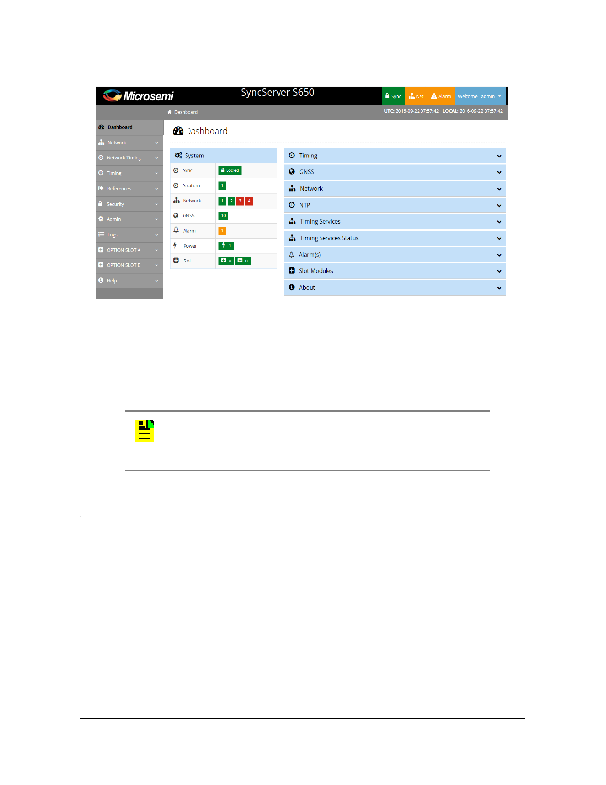
Figure 1-34. Web Interface - Dashboard
Chapter 1 Overview
Alarms
Command Line Interface (CLI)
The Command Line Interface can be used to control specific function of the
SyncServer S6x0 from a terminal connected to the EIA-232 serial port or the
Ethernet LAN1 port. Refer to Chapter 5, Command Line Interface (CLI) for further
details.
Alarms
The SyncServer S6x0 uses alarms to notify you when certain conditions are
deteriorating below specified levels or when issues arise, such as loss of power ,
loss of connectivity, or excess traffic on a port. These alarms are indicated by LEDs,
WebGUI status, CLI status, alarm connector (configurable), SNMP Trap
(configurable), message log (configurable), and email (configurable). For more
information, see Provisioning Alarms, on page 226 and Appendix A, System
Messages.
Note: Before you can communicate with the SyncServer S6x0
through an Ethernet connection, you must first configure the Ethernet
port using the serial connection or front panel (see
Ethernet Ports
, on page 182).
Provisioning the
098-00720-000 Revision D1 – February, 2018 SyncServer 600 Series User’s Guide 45
Page 46

Chapter 1 Overview
Alarms
46 SyncServer 600 Series User’s Guide 098-00720-000 Revision D1 – February, 2018
Page 47

Chapter 2 Installing
This chapter describes the procedures for installing the SyncServer S6x0.
In This Chapter
Getting Started
Unpacking the Unit
Rack Mounting the SyncServer S6x0
Installation Check List
Signal Connections
– Communications Connections
– SyncServer S6x0 Synchronization and Timing Connections
Connecting the GNSS Antenna
Installation Check List
Applying Power to the SyncServer S6x0
098-00720-000 Revision D1 – February, 2018 SyncServer 600 Series User’s Guide 47
Page 48

Chapter 2 Installing
Getting Started
Getting Started
Before you begin to install the SyncServer S6x0, review the information in this
section.
If you encounter any difficulties during the installation process, contact Microsemi
Frequency and Time Division (FTD) Services and Support. See Contacting
Technical Support, on page 248 for telephone numbers. Contact Microsemi FTD
Services and Support for technical information. Contact Customer Service for
information about your order, RMAs, and other information.
Security Considerations for SyncServer S6x0 Installation
The SyncServer S6x0 should be installed in a physically secure and restricted
location.
Whenever possible, the SyncServer S6x0's Ethernet ports should be installed
behind the company's firewall to prevent public access.
Site Survey
The SyncServer S6x0 can be installed in a wide variety of locations.
Before you begin installation, determine the chassis location, ensure the
appropriate power source is available (120/240 VAC), and ensure that the
equipment rack is properly grounded.
The SyncServer S6x0 is designed to mount in a 19-inch (48 cm) rack, occupies 1.75
in (4.5 cm, 1 RU) of vertical rack space, and has a depth of 15” (38.1 cm).
The SyncServer S6x0 is to be installed into a rack. The AC power connection is to
be made to a 120 or 240 VAC power receptacle following local codes and
requirements. An external Surge Protective Device is required to be used with the
AC version of the SyncServer S6x0.
Environmental Requirements
To prevent the unit from malfunctioning or interfering with other equipment, install
and operate the unit according to the following guidelines:
Operating temperature: –40Fto 149F (–20 C to 65C) for SyncServer S6x0
with quartz oscillator (standard or OCXO); 23Fto 131F (–5 C to 55C) for
SyncServer S6x0 with Rubidium oscillator.
Operating Humidity: 5% to 95% RH, maximum, w/condensation
48 SyncServer 600 Series User’s Guide 098-00720-000 Revision D1 – February, 2018
Page 49

Chapter 2 Installing
Unpacking the Unit
Secure all cable screws to their corresponding connectors.
Caution: To avoid interference, you must consider the
electromagnetic compatibility (EMC) of nearby equipment when you
install the SyncServer S6x0.
Electromagnetic interference can adversely affect the operation of
nearby equipment.
Installation Tools and Equipment
You will need the following tools and equipment to install the SyncServer S6x0:
Standard tool kit
Cable ties, waxed string, or acceptable cable clamps
1 mm² / 16 AWG wire to connect grounding lug to permanent earth ground
One UL listed Ring Lugs for grounding connections
Crimping tool to crimp the ring lug
Shielded cabling of the appropriate impedance required by the specific signal
type for signal wiring (including GNSS)
Mating connectors for terminating signal wiring
ESD wrist strap for installing modules
Fasteners for mounting the equipment in rack
Digital multimeter or standard Voltmeter for verifying ground connections to the
chassis
Unpacking the Unit
The SyncServer S6x0 is packaged to protect them from normal shock, vibration and
handling damage. (Each unit is packaged separately.)
Caution: To avoid ESD damage to parts that are packaged with the
SyncServer S6x0, observe the following procedures.
Unpack and inspect the unit as follows:
1. Wear a properly grounded protective wrist strap or other ESD device.
2. Inspect the container for signs of damage. If the container appears to be
damaged, notify both the carrier and your Microsemi distributor. Retain the
shipping container and packing material for the carrier to inspect.
098-00720-000 Revision D1 – February, 2018 SyncServer 600 Series User’s Guide 49
Page 50

Chapter 2 Installing
Rack Mounting the SyncServer S6x0
3. Open the container, being careful to cut only the packaging tape.
4. Locate and set aside the printed information and paperwork that is included in
the container.
5. Remove the unit from the container and place it on an anti-static surface.
6. Locate and set aside small parts which may be packed in the container.
7. Remove the accessories from the container.
8. Remove the anti-static packaging from the unit and accessories.
9. Verify that the model and item number shown on the shipping list agrees with the
model and item number on the equipment. The item number can be found on a
label affixed to the top of the unit. See Figure 2-1 for the location of the label on
the SyncServer S6x0. Contact your Microsemi distributor if the model or item
number do not match.
For a complete listing of item numbers, see Table 7-4, Table 7-5 and Table 7-6.
Figure 2-1. SyncServer S6x0 - Location of Product Label
Rack Mounting the SyncServer S6x0
The installation procedure described in this section provides general guidelines for
installing the SyncServer S6x0. Always follow applicable local electrical standards.
SyncServer S6x0 is shipped with 19-inch rack mounting brackets attached.
Mount the chassis to the front of the equipment rack rails with four screws and
associated hardware, as shown in Table 2-3. Use the proper screws for the
equipment rack.
50 SyncServer 600 Series User’s Guide 098-00720-000 Revision D1 – February, 2018
Page 51

Figure 2-2. Dimensions for SyncServer S6x0
Rack Mounting the SyncServer S6x0
Chapter 2 Installing
Figure 2-3. Rack Mounting the SyncServer S6x0
098-00720-000 Revision D1 – February, 2018 SyncServer 600 Series User’s Guide 51
Page 52

Chapter 2 Installing
Making Ground and Power Connections
Making Ground and Power Connections
The SyncServer S6x0 has either one or two 120/240 VAC connectors, depending
on the specific model, which are located on the left side of the rear panel. (see
Figure 2-4 and Figure 2-5).
Ground Connections
The frame ground connection is made using the grounding screw, which is marked
with the universal ground symbol, as shown in Figure 2-6. This screw is located on
the left side of the rear panel for all models of the SyncServer S6x0, as shown in
Figure 2-4 and Figure 2-5.
Figure 2-4. SyncServer S600/S650 Power & Ground Connections - Single AC Version
Figure 2-5. SyncServer S600/S650 Power & Ground Connections - Dual AC Version
Figure 2-6. Universal Ground Symbol
After installing the SyncServer S6x0 into the rack, connect the chassis to the proper
grounding zone or master ground bar per local building codes for grounding.
52 SyncServer 600 Series User’s Guide 098-00720-000 Revision D1 – February, 2018
Page 53

Making Ground and Power Connections
Chapter 2 Installing
Run a 16 AWG green/yellow-striped insulated wire from the SyncServer S6x0
grounding lug to the earth Ground on the rack. The rack grounding method is below.
Recommendation: Although there are a number of methods for
connecting the equipment to earth ground, Microsemi recommends
running a cable of the shortest possible length from the ground lug to
earth ground.
1. Remove the grounding screw from the rear panel of the SyncServer S6x0.
2. Crimp the customer-supplied UL listed Ring Lug to one end of the 16 AWG wire.
Coat the lug with an electrically conductive antioxidant compound such as
Kopr-shield spray. Use the grounding screw to connect the ring lug to the left side
of the rear panel. The surface of the SyncServer S6x0 rear panel and threads
where the grounding screw attaches must be clean of contaminants and
oxidation.
3. Connect the other end of the 1 mm² / 16 AWG green/yellow-striped wire to earth
ground using local building electrical codes for grounding
.
The suggested method is to crimp the appropriate customer-supplied UL listed
Ring Lug to the other end of the 1 mm² / 16 AWG green/yellow-striped wire.
Remove the paint and sand the area around the screw hole to ensure the proper
conductivity. Coat the connection with an electrically conductive antioxidant
compound such as Kopr-shield spray. Connect this Ring Lug to the rack with
appropriate customer supplied screws and external star lock washers, tightening
to a torque value of 53.45 in-lbs.
4. Using a digital voltmeter, measure between the ground and chassis and verify
that no voltage exists between them.
098-00720-000 Revision D1 – February, 2018 SyncServer 600 Series User’s Guide 53
Page 54

Chapter 2 Installing
Making Ground and Power Connections
AC Power Connection
Use the following procedure to make the power connections for the AC version of
the SyncServer S6x0. An Over-Current Protection Device must be placed in front of
the shelf power.
Figure 2-7. SyncServer S6x0 Single AC Power Connector
Figure 2-8. SyncServer S6x0 Dual AC Power Connector
Warning: To avoid possible damage to equipment, you must provide
power source protective fusing as part of the installation. The
SyncServer S6x0 is intended for installation in a restricted-access
location.
1. Insert the female end of the AC power cord into the AC power connector on the
SyncServer S6x0. The power receptacles support IEC cable with V-locks. The
V-lock will latch the cable to prevent accidental removal of the power cord.
2. Plug the male end of the AC power cord into an active 120 VAC or 240 VAC
power socket.
3. For dual AC versions, repeat steps 1-2 for the second AC power connector.
DC Power Connection
Use the following procedure to make the power connections for the DC version of
the SyncServer S6x0. An Over-Current Protection Device must be placed in front of
the shelf power. The SyncServer S6x0 uses a Molex HCS-125 series connector.
54 SyncServer 600 Series User’s Guide 098-00720-000 Revision D1 – February, 2018
Page 55

Chapter 2 Installing
Signal Connections
Warning: To avoid possible damage to equipment, you must provide
power source protective fusing as part of the installation. The
SyncServer S6x0 is intended for installation in a restricted-access
location.
1. Create a custom cable using the supplied Molex connector housing and
terminals. The terminals need to be crimped to the wires.
2. Connect the other end of the DC cable to nominal 24VDC or 48 VDC.
3. Repeat steps 1-2 for the second DC power connector.
4. The positive wire must be connected to the positive terminal (+) and the negative
wire to the negative terminal (-). The ground connection should only be
connected to ground and not to a power supply.
Figure 2-9. SyncServer S6x0 Dual DC Power Connectors
Signal Connections
The connectors for the SyncServer S6x0 are located on the rear panel.
Communications Connections
The communication connections allow user control of the SyncServer S6x0. The
EIA-232 serial port and Ethernet port 1 (LAN1) are located on the rear panel are
shown in Figure 1-9.
098-00720-000 Revision D1 – February, 2018 SyncServer 600 Series User’s Guide 55
Page 56

Chapter 2 Installing
Signal Connections
Ethernet Port 1
Ethernet port 1 is a standard 100/1000 Base-T shielded RJ-45 receptacle on the
rear panel of the unit. It is used to provide connectivity to a web interface and to an
Ethernet local area network (as well as for NTP input/output). To connect the
SyncServer S6x0 to an Ethernet network, use an Ethernet RJ-45 cable. See Table
2-2 for connector pinouts.
Serial (Console) Port
The serial port connection is made through a DB-9 female connector on the rear
panel of the unit. This port, which supports a baud rate of 115.2k (115200-8-1-N-1),
allows you to connect to a terminal or computer using a terminal emulation software
package for remote monitoring and control. This port is also used for serial data
(NENA ASCII time code, Response mode). When connecting to this port, use a
shielded serial direct connect cable.
Figure 2-10. Serial Port Male Mating Connector Pins
Figure 2-11 shows the DB-9 male connector that mates with the serial port on the
SyncServer S6x0.
Figure 2-11. Serial Port Male Mating Connector Pins
Table 2-1 describes the DB-9 connector pin assignments for the serial port
.
Table 2-1. Serial Port Connector Pin Assignments
Signal Pin
TXD 2
RXD 3
Ground 5
56 SyncServer 600 Series User’s Guide 098-00720-000 Revision D1 – February, 2018
Page 57

Chapter 2 Installing
Signal Connections
SyncServer S6x0 Synchronization and Timing Connections
The SyncServer S6x0 has one GNSS input and four NTP input/output connections.
The SyncServer S6x0 has one 1PPS output. The SyncServer S650 may also have
an optional Timing I/O Module.
GNSS Connection
To connect a GNSS signal to the SyncServer S6x0, you must install a GPS
antenna. See Connecting the GNSS Antenna, on page 61.
Caution: The GNSS cable should only be connected while the unit is
properly earth grounded.
Warning: To avoid possible damage to equipment, you must provide
external lightning protection when installing the GNSS antenna to
prevent transients.
Ethernet Connections
The Ethernet ports are standard 100/1000 Base-T shielded RJ-45 receptacles,
which are used for NTP inputs. To connect the SyncServer S6x0 to an Ethernet
network, use an Ethernet RJ-45 cable. See Table 2-2 for connector pinouts.
Table 2-2. System Management Ethernet Connector Pin Assignments
RJ-45 Pin
1 TX+ (Transmit positive) BI_DA+
2 TX- (Transmit negative) BI_DA
3 RX+ (Receive positive) BI_DB+
4 Not Used BI_DC+
5 Not Used BI_DC
6 RX- (Receive negative) BI_DB
7 Not Used BI_DD+
8 Not Used BI_DD
100Base-T Signal 1000Base-T Signal
098-00720-000 Revision D1 – February, 2018 SyncServer 600 Series User’s Guide 57
Page 58

Chapter 2 Installing
Signal Connections
Figure 2-12. Ethernet Connections
10 GbE Connections
The two SFP+ ports are only available with the 10 GbE option. These SFP+ ports
are equipped with hardware timestamping that supports NTP, PTP, and NTP
Reflector operations. These ports are ideal for interoperability with 10 GbE
switches. SFP modules supported are limited to 10 GbE speeds only, See Table 2-3
for a list or recommended and supported SFP+ transceivers.
Figure 2-13. 10 GbE Connections
Table 2-3. Recommended and Supported SFP+ (10GbE) Transceivers
Vendor
ALU multi-mode 10GBASE-SR,
ALU single mode 10GBASE-LR,
Finisar multi-mode PN: FTLX8573D3BTL
Finisar multi-mode PN: FTLX8574D3BCL
Finisar single mode PN: FTLX1471D3BCL
Mode Item Code or P/N
PN: 3HE04824AA
PN: 3HE04823AA
D-Link multi-mode 10GBASE-SR,
PN: DEM-431XT-DD
Cisco multi-mode SFP-10G-SR
58 SyncServer 600 Series User’s Guide 098-00720-000 Revision D1 – February, 2018
Page 59

Table 2-3. Recommended and Supported SFP+ (10GbE) Transceivers
Chapter 2 Installing
Signal Connections
Vendor
Cisco single mode SFP-10G-LR
Juniper multi-mode SFPP-10G-SR
Juniper single mode SFPP-10G-LR
Juniper multi-mode EX-SFP-10G-SR
Juniper single mode EX-SFP-10G-LR
Mode Item Code or P/N
Timing I/O Module Connections
The standard configuration offers a broad yet fixed selection of signal I/O on its eight
BNC connectors (see Figure 1-26). J1 is dedicated to time code and rate inputs, J2
to sine wave inputs, and J3-J8 to mixed signal outputs. The standard Timing I/O
Module configuration is 1PPS or IRIG B AM-In, 10 MHz- In, IRIG AM and IRIG
DCLS-Out, 1PPS-Out and 10 MHz-Out.
The FlexPort™ Technology option enables the 6 output BNCs (J3-J8) to output any
supported signal (time codes, sine waves, programmable rates, and so on.) on all
configurable in real time via the secure web interface. Similarly, the 2 input BNCs
(J1-J2) can support a wide variety of input signal types. This uniquely flexible BNC
by BNC configuration makes very efficient and cost effective use of the 1U space
available.
See Figure 1-27 to view the signal types for the standard configuration and the
configuration with the FlexPort™ option. See Figure 2-14.
Figure 2-14. Timing I/O BNC Connections
098-00720-000 Revision D1 – February, 2018 SyncServer 600 Series User’s Guide 59
Page 60

Chapter 2 Installing
Signal Connections
LPN Module Connections
This module provides low phase noise 10 MHz signals on all eight ports (J1-J8).
See Figure 2-15.
Figure 2-15. LPN BNC Connections
Serial Timing Connection
The SyncServer S6x0 features a DB-9 female connector on the rear panel of the
unit. This port supports a baud rate of 4800 to 115.2k (115200-8-1-N-1). When
connecting to this port, use a shielded serial direct connect cable. See Figure 2-16.
See Table 2-4 for pin-outs for this RJ-45 connector.
Figure 2-16. Data/Timing Connection
.
Table 2-4. Serial Data/Timing Port Pin-Outs - DB9 Connector
Signal Pin
TXD 2
RXD 3
Ground 5
See Table B-16
in Appendix B for TOD format details.
60 SyncServer 600 Series User’s Guide 098-00720-000 Revision D1 – February, 2018
Page 61

1PPS Output Connection
The SyncServer S6x0 features a single BNC female connector for the 1PPS signal.
See Figure 2-17.
Figure 2-17. 1PPS Output Connection
Connecting the GNSS Antenna
Caution: The GNSS cables should only be connected while the unit
is properly earth grounded.
Connecting the GNSS Antenna
Chapter 2 Installing
The antenna connections for the SyncServer S6x0 are made at the BNC female
connector labeled GNSS. Allow at least one hour for the unit to track and lock to
GNSS satellites, though it typically takes far less time provided the antenna has an
adequate view of the sky.
Note: The SyncServer S650i does not include a GNSS antenna
connector.
Figure 2-18. GNSS Input Connection
Proper cable, grounding techniques, and lightning arrestors should be used. Mount
the antenna outside, preferably on the roof with an unobstructed view of the sky.
Avoid mounting the antenna near a wall or other obstruction blocking part of the sky.
Mount the antenna well above roads or parking lots.
Note: For the best possible timing accuracy the cable delay must be
determined and entered into SyncServer S6x0 with the web interface.
See
Table C-1 for cable delay values of SyncServer S6x0 GNSS
antenna kits.
098-00720-000 Revision D1 – February, 2018 SyncServer 600 Series User’s Guide 61
Page 62

Chapter 2 Installing
Connecting Alarm Relay
Warning: To avoid serious personal injury or death, exercise caution
when working near high voltage lines. In particular:
Use extreme caution when installing the antenna near, under, or
around high voltage lines.
Follow local building electrical codes for grounding the chassis.
Connecting Alarm Relay
The alarm relay output is open when an alarm activation on this page is configured
and the alarm is in alarm state:
ALARM=OPEN
Note: The SyncServer S650i does not include a GNSS antenna
connector.
The external Alarm mating connector is not supplied. The mating connector is made
by Phoenix Contact, and the manufacturer's part number is 1827703.
Figure 2-19. Alarm Connections
Installation Check List
To verify that the installation of the SyncServer S6x0 is complete, perform the
checks and procedures in Table 2-5.
Table 2-5. Installation Completeness Checklist
Operation Complete
Ensure the SyncServer S6x0 chassis is securely attached to mounting rack
Verify that all power and ground wires are installed correctly and securely
Verify that all communications cables are properly installed
Verify that all input and output cables are properly installed
62 SyncServer 600 Series User’s Guide 098-00720-000 Revision D1 – February, 2018
Page 63

Applying Power to the SyncServer S6x0
Applying Power to the SyncServer S6x0
The SyncServer S6x0 is not equipped with a Power switch. After installing the unit
in a rack and making the necessary connections described in previous sections,
turn on power at the distribution panel.
Normal Power Up Indications
As the SyncServer S6x0 powers up and begins normal operation, the LEDs all turn
on. After the self-test is complete and the firmware is operational, the LED states
may change to indicate the appropriate state or status.
Table 2-6 provides a description of the SyncServer S6x0 LEDs.
Table 2-6. LED Descriptions
Label LED Description
Chapter 2 Installing
SYNC Clock Status Green - Time or Frequency clock in Normal or
Bridging state
Amber - Time or Frequency clock in Freerun or
Holdover state
NETWORK Network Status Red - Management port (LAN1) is not configured
or is down
Amber - Some configured ports are down (LAN2
to LAN4)
Green - All configured ports are up
ALARM Alarm
System alarm/fault indicator
Off -Operating normally
Amber - Minor Alarm(s)
Red - Major/Critical Alarm(s)
The SyncServer 6x0 does not contain a battery-backed real time clock. Therefore, it
will always boot up with a default value for the system time. This time will be
updated when it obtains time from a time reference such as GNSS, IRIG, or NTP.
The default value for the date is the software build date. This date will be used for
the first log entries when booting up the unit. The time will change to local time
during the boot-up process if a time zone has been configured.
098-00720-000 Revision D1 – February, 2018 SyncServer 600 Series User’s Guide 63
Page 64

Chapter 2 Installing
Applying Power to the SyncServer S6x0
64 SyncServer 600 Series User’s Guide 098-00720-000 Revision D1 – February, 2018
Page 65

Chapter 3 Keypad / Display Interface
This chapter describes the keypad / display interface.
Overview
The keypad / display interface displays the time, system status, and provides the
following functions:
Configuring and enabling/disabling the LAN1 network port.
Setting the time and entering freerun mode.
Adjusting the brightness.
Locking the keypad.
Shutting down the SyncServer.
When the SyncServer starts, the display shows "Booting SyncServer please wait...".
Shortly thereafter, the SyncServer displays the default time screen.
The following buttons are user-input devices for the keypad/display interface.
ENTER: Use with MENU - Applies a menu selection or function setting.
CLR: Use with MENU - Returns to the previous screen without saving changes.
Left/Right Arrow Buttons: In functions, will change where the next number will be
entered left or right. In status, scrolls a screen horizontally when
"<previous:next>" is displayed.
Up/Down Arrow Buttons: In functions, will change where the next number will be
entered. In status, scrolls a screen vertically, displays the previous/next screen.
Number Buttons: Enters a number, or selects a numbered menu item.
The following three buttons change the function of the display.
TIME: Changes the format and contents of the time display.
STATUS: Displays status of basic SyncServer operational conditions.
MENU: Displays a menu of functions.
The following sections cover these three buttons in more detail.
098-00720-000 Revision D1 – February, 2018 SyncServer 600 Series User’s Guide 65
Page 66

Chapter 3
TIME Button
TIME Button
Cycling the TIME button changes the predefined format and contents of the time
display:
Large numeric time display on full screen. Hours:Minutes:Seconds
Medium numeric time display on the left, current reference and NTP Stratum on the
right
Small date and time, reference, and NTP stratum.
The time display also indicates a time scale:
If the time zone setting on the TIMING - Time Zone web page is set to UTC, the time
display shows "UTC" as the time scale.
If the time zone setting on TIMING - Time Zone page is set to a non-UTC (local)
time zone, the time display leaves the time scale blank, or adds AM/PM if the user
selects the 12-hour time scale. (Press the MENU button and select 2) Display > 3)
12/24 > 1) 12 (AM/PM).
If the Ignore UTC Corrections from GPS Reference setting on the TIMING - HW
Clock page is enabled (selected), the time display shows "GPS" as the time scale.
Note: The TIMING - Time Zone page configures the display for UTC or local time.
The TIMING -
STATUS Button
Pressing the STATUS button repeatedly displays a series of status screens for:
NTP
Alarms
Network Ports
Clock
GNSS Receiver
SyncServer model, serial number, software version, and software upgrade
availability. If installed, the configuration for each port of the timing/IO module.
66 SyncServer 600 Series User’s Guide 098-00720-000 Revision D1 – February, 2018
Page 67

Chapter 3
STATUS Button
Figure 3-1. NTP Status Screen
Some screens have a "Next>" in the upper right. This means more information is
available by pressing the right arrow button. This cycles through screens on that
topic.
NTP Status Screen
Network Time Protocol (NTP) status.
Stratum: The Stratum number of the SyncServer. Stratum 1 means it is locked to a
Hardware Clock.
Hardware Clock Input Reference that is a Stratum 0 source. Stratum 2-15 means
the SyncServer is locked to another NTP time source. Stratum 16 means that the
SyncServer is unsynchronized.
Reference: This field identifies the "system peer". While stratum is 16, this field
shows the progression of the NTP clock PLL. The field starts with a value of "INIT".
Once a peer has been selected, the clock may be stepped, in which case the
reference ID field changes to "STEP".
Once the PLL is locked, the stratum is updated and the reference ID provides
information about the selected peer. When the SyncServer is operating at stratum 1,
the reference ID displays the name of the Hardware Clock reference input.
NTP Packet I/O: The number of NTP packets the SyncServer has replied to and
initiated. The SyncServer replies to clients that send NTP requests. The SyncServer
also sends NTP requests when the NTP daemon isn't synchronized (i.e., Sync LED
is RED) and when it is configured to synchronize to an NTP association (e.g., a
Server type association).
Alarm Status Screen
Current alarm status. Use the right or left arrow to show details about the alarms.
Major: List of up to three current major alarms
Minor: List of up to three current minor alarms
LAN Status Screens
Multiple screens, four for each network port. There are two screen for IPv4 and two
for IPv6. Use Next> to see the entire IP address configuration.
098-00720-000 Revision D1 – February, 2018 SyncServer 600 Series User’s Guide 67
Page 68

Chapter 3
STATUS Button
State: Shows “Up” if the port is enabled and “Down” if the port is disabled.
IP: IP address for the port
SM: Subnet mask
GW: Gateway address
Clock Status Screen
Hardware Clock and Input Reference status.
GNSS Receiver Status Screen
GNSS receiver status.
Antenna: OK
GNSS: Operational
GNSS SATELLITES
– GPS: number of GPS satellites currently being tracked.
– GLONASS: number of GLONASS satellites currently being tracked
– SBAS: number of SBAS satellites currently being tracked
– Max CNo: The highest CNo (Carrier-to-Noise ratio) of all satellites (value
given for each satellite type)
GNSS SOLUTION
Status: OK Service 3D
Mode: Auto or Manual
SyncServer Status Screen
Hardware and software identification. Software upgrade availability.
Model: The model number.
S.N.: The serial number.
Version: The software "Release Version" number.
Option Slot A/B Status Screens
Shows the configuration of each of the slot A/B input and output connections.
68 SyncServer 600 Series User’s Guide 098-00720-000 Revision D1 – February, 2018
Page 69

Option: Description of installed module (if any)
Flex I/O Option: Enabled | Disabled
J1 Input: Configuration of input
J2: Input: Configuration of input
J3 Output: Configuration of output
J4 Output: Configuration of output
J5 Output: Configuration of output
J6 Output: Configuration of output
J7 Output: Configuration of output
J8 Output:Configuration of output
Chapter 3
MENU Button
MENU Button
Pressing the MENU button presents a numbered menu of functions, as shown in
Figure 3-2.
Figure 3-2. Menu of Functions
LAN1
Selecting LAN1 brings up the Display menu screen on the display, as shown in
Figure 3-3.
Figure 3-3. Configure LAN1 Screen
1. Configure: Use to select IPv4 or IPv6 address mode for LAN1 port. IPv6
automatically configures LAN1 with a dynamic IPv6 address.
If Configure is selected, the Select LAN1 screen will appear, as shown in Figure
3-4.
098-00720-000 Revision D1 – February, 2018 SyncServer 600 Series User’s Guide 69
Page 70

Chapter 3
MENU Button
2. On/Off: Use On to enable the LAN1 network port. Off disables the LAN1 network
port for all traffic types.
Figure 3-4. Select LAN1 IP Mode Screen
1. IPv4: Select IPv4address mode for LAN1 port.
If IPv4 is selected, the Select Addressing Type screen will appear, as shown in
Figure 3-5.
2. IPv6: Select IPv6 address mode for LAN1 port.
If IPv6 (DHCPv6) is selected, the SyncServer automatically configures LAN1 with
a dynamic IPv6 address.
Figure 3-5. Select IPv4 Addressing Type Screen
1. Static Addr: Select IPv4address mode for LAN1 port.
If Static Address is selected, the Enter LAN1 Address screen will appear, as
shown in Figure 3-6. After the address is entered press the ENTER button and
you will be prompted to enter the Subnet mask (then ENTER) followed by the
Gateway address. Once the gateway address has been entered the LAN 1 port
will be reconfigured.
2. DHCP: Select DHCP addressing type for LAN1 port. DHCP automatically
configures LAN1 with a dynamic IPv4 address.
Figure 3-6. Enter LAN1 Static IPv4 Address Screen
Display
Selecting Display brings up the Display menu screen on the display, as shown in
Figure 3-7.
70 SyncServer 600 Series User’s Guide 098-00720-000 Revision D1 – February, 2018
Page 71

Chapter 3
MENU Button
Figure 3-7. Display Menu Screen
1. Set Time: Enter the UTC date and time using 24-hour format. Select OK to apply
the entered time to the Hardware Clock and not use external time references.
See Figure 3-8.
Figure 3-8. Set Time Screen
2. Brightness: Adjust the brightness of the front panel display. See Figure 3-9.
Figure 3-9. Set Brightness Screen
3. 12/24 (non-UTC Only): Select a 12 (AM/PM) or 24-hour clock format. See Figure
3-10.
Note: The 12/24 and 24 Hour only appear if a local time zone has
been specified via the web inteface.
Figure 3-10. Select Time Format Screen
Many keypad functions timeout after approximately 10 seconds of inactivity (no user
inputs).
Sys Control
Selecting Sys Control brings up the Shutdown / Factory Default screen on the
display, as shown in Figure 3-11.
098-00720-000 Revision D1 – February, 2018 SyncServer 600 Series User’s Guide 71
Page 72

Chapter 3
MENU Button
Figure 3-11. Shutdown / Factory Default Screen
See Factory Defaults in Appendix B for default settings.
1. Shutdown: Halts the SyncServer. The message Press the ENTER button to
Confirm appears in the display, as shown in Figure 3-12.
2. Factory Default
Figure 3-12. Confirmation Screen
Keypad
Selecting Keypad brings up the Keypad Control screen on the display, as shown in
Figure 3-13.
Figure 3-13. Keypad Control Display Screen
1. Set Password: Sets the password for the Lockout function. The *first time* the
interface asks for the "Current Password", enter 95134. No password recover or
reset feature is available for the keypad, except to reset factory defaults using the
Sys Control - Factory Reset page.
2. Lockout: The Lockout function password protects the keypad from changes.
Asks for confirmation. The factory default password for the keypad is “95134”.
72 SyncServer 600 Series User’s Guide 098-00720-000 Revision D1 – February, 2018
Page 73

Chapter 4 Web Interface
This chapter describes the web interface for the SyncServer S6x0.
See Communicating Through LAN1 Ethernet Port, on page 176 for details on how
to access the web interface.
In This Chapter
System Information
Status / Information Windows
Navigation Windows
Note: For security reasons, the SyncServer S6x0 only supports https
However, the user will get warnings from most web browsers that a
self-signed certificate is being used (not from a recognized certificate
authority). Users should accept the warnings and proceed to the login
page.
The internal self-signed certificate can be renewed and updated on
the Security->https page. Users can also request and install a https
certificate
Figure 4-1. Login
For security reasons, the SyncServer S6x0 will lock out a user if an invalid
password is entered three times. The user is locked out for 1 hour. The lockout is
also removed if the unit is rebooted.
Note: The default user name is “admin” and the default password is:
Microsemi .
To avoid unauthorized access, you should change the default
password.
098-00720-000 Revision D1 – February, 2018 SyncServer 600 Series User’s Guide 73
Page 74

Chapter 4
System Information
Figure 4-2. Dashboard Screen
Note: UTC and local time are displayed in the upper right portion of
the page. Local time is based on the timezone setting in the
SyncServer unit. Daylight saving time is also applied to the local time
if applicable. Local time is not determined by the location of the web
browser.
Note: If the browser is displaying a busy indicator, then please wait
until the previous action is complete before starting another action.
Depending on the browser used, the web page responsiveness will
vary due to the use of the encryption cipher suite used in the S6x0.
Microsemi recommends using the Google Chrome browser.
System Information
The System information window in the Dashboard, as shown in Figure 4-3, displays
an overall summary of the system.
74 SyncServer 600 Series User’s Guide 098-00720-000 Revision D1 – February, 2018
Page 75

Figure 4-3. System Status
Status / Information Windows
Status / Information Windows
Chapter 4
The Status/Information windows in the dashboard, as shown in Figure 4-4, displays
status details and information regarding the following:
Timing
GNSS
Network
NTP
Timing Services
Timing Services Status
Alarms
Slot Modules
About
Clicking on the down arrow on a window expands the information under that topic.
098-00720-000 Revision D1 – February, 2018 SyncServer 600 Series User’s Guide 75
Page 76

Chapter 4
Status / Information Windows
Figure 4-4. Status/Information Windows
Timing Status & Information
The Timing window in the dashboard, as shown in Figure 4-5, displays status
details and information about system timing, including current reference, lock
status, and status of input references. See Table 4-1.
Figure 4-5. Timing Window
76 SyncServer 600 Series User’s Guide 098-00720-000 Revision D1 – February, 2018
Page 77

Note: The SyncServer 6x0 does not contain a battery-backed
real time clock. Therefore, it will always boot up with a default
value for the system time. This time will be updated when it
obtains time from a time reference such as GNSS, IRIG, or
NTP. The default value for the date is the software build date.
This date will be used for the first log entries when booting up
the unit. The time will change to local time during the boot-up
process if a time zone has been configured.
Table 4-1. Timing Window Descriptions
Item Details Color Scheme
Status / Information Windows
Chapter 4
Time of Day Status This row is essentially showing the
time clock state.
See
Table 4-2 for descriptions of
clock states.
Current Reference This row shows the input reference
that is currently “driving” the
SyncServer. It could be a timing
source (best case), an external
holdover source, or the SyncServer
internal reference (worst case).
See
Table 4-3 for details of current
sources.
Timing References This row shows all enabled time
references.
Warmup
Freerun
Handset
Locking
Locked
Bridging
Holdover
Holdover
Recovering
Green if any externally
selected reference,
Amber color only if internal
oscillator.
If a time reference is ready to
be used it will be
If it is not ready it will be
green.
red.
098-00720-000 Revision D1 – February, 2018 SyncServer 600 Series User’s Guide 77
Page 78

Chapter 4
Status / Information Windows
Table 4-1. Timing Window Descriptions
Item Details Color Scheme
Frequency
References
Leap Pending This row indicates if a Leap second is
This row shows all enabled
frequency-only references.
The use of a frequency reference is
thought of as a method for
holding-over time when there either
was never an active time source or it
was lost.
pending.
The SyncServer S600/S650 has separate timing and frequency clock controls. The
time and frequency clocks are usually in the same clock state. If they are different,
then the “Current Reference” row will include text after the icon which displays the
frequency clock state. The “Time of Day Status” always shows the time clock state.
While locking to a new reference, the two states may be different for a brief time.
If a holdover source is ready
to be used it will be
If it is not ready it will be
If there is no warning of a
Leap second pending it will
be
green.
If there is a warning of a Leap
second pending it will be
green.
red.
red.
If there are no valid timing references, but there is a valid frequency reference, then
there should be text shown since the frequency and time clock states are different.
The system time locks, but does not frequency lock to an NTP reference.
Therefore, the frequency status will display free-run while the system is locked to an
NTP reference and there are no frequency references connected.
78 SyncServer 600 Series User’s Guide 098-00720-000 Revision D1 – February, 2018
Page 79

Status / Information Windows
Table 4-2. Status - Clock State Descriptions
Status Indication Meaning Details
Chapter 4
Warmup SyncServer not ready for any type of
synchronization functionality. This is a
one-time status following power-up
Freerun SyncServer does not have a time
reference and never has had one since
powerup.
Handset For future use.
Locking SyncServer has selected a qualified
active time input for use and is now in
process of aligning all outputs to it.
Locked SyncServer outputs are now aligned to a
selected active time source.
Bridging SyncServer no longer has a selected
active time source, but it hasn’t been that
way for very long.
Directly equal to the common
warmup clock state (to both freq
and time)
In this status, the Current
Source row will, by definition,
have a “green” item that has a
match to it in the Timing
Sources row.
An “active” time source just
means one that is continuously
providing time (where
continuous is a relative term –
in general it is an update per
second).
This is really just the beginning
of holdover, but is a period
where the output performance
should be as good as when in
Locked. It provides a hysteresis
buffer to prevent nuisance
Locked-Holdover-Locked
transitions.
In this state the Current Source
row will NOT have a green item
from the Timing Sources row.
Holdover SyncServer no longer has a selected
active time source, and it has been that
way for longer than the Bridging
duration. Also the condition for “red
holdover” (next row) is not met.
098-00720-000 Revision D1 – February, 2018 SyncServer 600 Series User’s Guide 79
Either we are holdover using an
external frequency reference
OR we are in holdover using the
SyncServer internal reference
AND the duration is less than a
user-specified time duration.
1
Page 80

Chapter 4
Note:
Status / Information Windows
Table 4-2. Status - Clock State Descriptions (Continued)
Status Indication Meaning Details
Holdover Same as prior row but specific additional
conditions are met.
This condition occurs if the current
source is the internal oscillator and the
duration in time holdover has exceeded
the time defined by user in the Timing >
Holdover window.
The unit has been in holdover
for more than a user-specified
duration and the holdover is
based on the SyncServer
internal reference.
In this case the Holdover
Sources row will not contain any
green items.
Relocking SyncServer has selected a qualified
active time input for use and is now in
process of aligning all outputs to it.
1
The main purpose of holdover is to allow the S6xx time server to continue to operate as "normal" using the
internal oscillator or external frequency reference even though the connection the GNSS is lost. The user
defines how long this holdover period will last. During this time the NTP Reference Time Stamp is updated
regularly indicating the S6xx is still connected to a time reference. Once the user defined holdover period is
exceeded the reference time stamp is no longer updated. This is important information to provide to NTP
clients as they can then determine whether or not to continue to synchronize to the S6xx. Once the S6xx
reacquires GNSS and relocks, the NTP Reference Time Stamp will again be updated regularly.
By NTP protocol definition, once an NTP server locks to a time reference and sets the Leap Indicator to 00
from 11 it never returns to 11. In other words, once the unit has left stratum 16 it should never return to
stratum 16. Instead it uses the reference time stamp behavior mentioned above.
80 SyncServer 600 Series User’s Guide 098-00720-000 Revision D1 – February, 2018
Page 81

Table 4-3. Status - Current Source Details
Status / Information Windows
Chapter 4
Item
Status Where it Will
Happen
Details
No current source Warmup Directly equal to the common warmup
clock state (to both freq and time)
Current Source taken
from Timing
References
Locking
Locked
Relocking
When the status is any of these there
MUST be a selected time source, which
takes precedence in the Current Reference
row (more important than if there is also a
qualified frequency reference). There must
be at least one green item in the Timing
References row. The leftmost green one
will be identically indicated in the Current
Reference row. This is because the
leftmost green item in Timing References is
the highest priority time source and
therefore must be selected. For example, if
it is GNSS it will appear identically as
Current Reference and in Timing
References row.
Current Source taken
from Frequency
References
Freerun
Bridging
Holdover
Holdover
For any Status in this category there cannot
be a qualified Timing Reference (nothing
green in that row), so it is certain that
SyncServer is using frequency-only
reference. If there is a qualified Frequency
Reference (meaning something green in
this row), then the leftmost green one will
be the current source.
If there is no qualified Frequency
Reference (nothing green in that row) then
all that remains is the SyncServer internal
reference, which is what appears in the
Current Reference row. In this case the
entry will be one of the following,
depending on the specific SyncServer
product oscillator type:
Internal Rb,
Internal OCXO
Standard
098-00720-000 Revision D1 – February, 2018 SyncServer 600 Series User’s Guide 81
Page 82

Chapter 4
Status / Information Windows
GNSS Status & Information
The GNSS window in the dashboard, as shown in Figure 4-6, displays status details
and information about GNSS. C/No is the carrier-to-noise density which is defined
as the carrier power divided by the noise power spectral density. Higher C/No
results in better tracking and performance.
The GNSS signal strength (C/No) can vary from 1 to 63. Typical values for a good
GNSS installation will be between 35 and 55.
Figure 4-6. GNSS Window
Table 4-4. GNSS Window - Descriptions
Field Potential Values Notes
GNSS Lists number of satellites being tracked
Antenna Status
Receiver Status
82 SyncServer 600 Series User’s Guide 098-00720-000 Revision D1 – February, 2018
OK - operating normally
Open - open circuit in antenna cable
or no DC load in splitter
Short - short circuit in antenna cable
Initializing - temporary condition
Invalid - not tracking
Tracking NO UTC - tracking, but
UTC offset not known
Tracking - tracking
Page 83

Table 4-4. GNSS Window - Descriptions
Field Potential Values Notes
Position Status No Data - no position data
Survey 2D - calculated 2D position,
lat/lon but no elevation
Survey - calculating position and
surveying to average position
Position Fix - position fixed, either
manual or to surveyed position
Position Position - latitude, longitude, and
height/elevation
Status / Information Windows
Chapter 4
Firmware Upgrade
Network Status & Information
The Network window in the dashboard, as shown in Figure 4-7, displays status
details and information about the network ports in use.
Figure 4-7. Network Window
Never run - upgrade process not run
In progress - GNSS receiver being
upgraded
Not required - GNSS receiver
firmware is at correct revision
Successful - GNSS receiver
firmware upgraded
Failed - GNSS receiver firmware
upgrade failed
Interrupted - GNSS receiver
firmware upgrade failed
If failed or interrupted conditions
persist, the unit should be
rebooted.
098-00720-000 Revision D1 – February, 2018 SyncServer 600 Series User’s Guide 83
Page 84

Chapter 4
Status / Information Windows
NTP Status & Information
The NTP window in the dashboard, as shown in Figure 4-8, displays status details
and information about the NTP configuration.
Figure 4-8. NTP Window
Note: The dashboard will provide Leap indicator information as soon
as it is available. For GPS, this is usually many months ahead.
The Leap indicator information in the NTP messages sent out the
Ethernet port(s) will only be sent out the last 24 hours before the
event for the "01" or "10" values of this parameter. See
more details about the Leap indicator.
Table 4-5 for
Timing Services Information
The Timing Services window in the dashboard, as shown in Figure 4-9, displays
status details and information about the NTP reflector and PTP configuration.
Figure 4-9. Timing Services Window
Timing Services Status
The Timing Services Status window in the dashboard, as shown in Figure 4-10,
displays status details and information for the NTP reflector and PTP.
Note: The row labeled with "Service" is a configuration of the port.
The Timing Services Status window shows this configuration. For
PTP, the actual PTP Grandmaster operational state as either Passive
or Master is found in the window Network Timing > NTPr/PTP Status,
in the row "Port State". See
84 SyncServer 600 Series User’s Guide 098-00720-000 Revision D1 – February, 2018
Figure 4-27.
Page 85

Figure 4-10. Timing Services Status Window
Alarm Information
Status / Information Windows
Chapter 4
The Alarms window in the dashboard, as shown in Figure 4-11, displays active
alarms.
Figure 4-11. Alarms Window
Slot Modules Status & Information
The Slot Modules window in the dashboard, as shown in Figure 4-12, displays
status details about the modules installed in the Options Slots.
Figure 4-12. Slot Modules Window
“About” Device Information
The “About” window in the dashboard, as shown in Figure 4-13, displays system
information about the unit.
098-00720-000 Revision D1 – February, 2018 SyncServer 600 Series User’s Guide 85
Page 86

Chapter 4
Navigation Windows
Figure 4-13. About Window
Note: The update available feature will only function if LAN1 has
been configured with an IPv4 address and a DNS server is
configured. The DNS server can be either automatically configured
via DHCP or manually when using a static IP address. The update
available feature can be disabled on the Admin->General page.
Note: You can check for the latest version number of SyncServer
S600 and S650 software at these URLs:
http://update.microsemi.com/SyncServer_S600
http://update.microsemi.com/SyncServer_S650
The number of the most current version of the software will appear.
You can compare this to the version number installed in the
SyncServer by proceeding to the web GUI Dashboard and finding the
version number in the About drop down on the right side. If you do not
have the latest version installed consider contacting Technical
Support.
Navigation Windows
The navigation portion of the web interface is used to access the various pages to
configure different aspects of the SyncServer S6x0 and to view status information.
See Figure 4-14. The navigation menu will expand and contract depending on the
current selection.
86 SyncServer 600 Series User’s Guide 098-00720-000 Revision D1 – February, 2018
Page 87

Figure 4-14. Navigation Portion of Dashboard
Navigation Windows
Chapter 4
098-00720-000 Revision D1 – February, 2018 SyncServer 600 Series User’s Guide 87
Page 88

Chapter 4
Navigation Windows
Network Configuration Windows
The Network tab on the dashboard provides access to windows for Ethernet, SNMP,
SNMP Trap configuration, and Ping.
Network - Ethernet Configuration
Use this window to configure or modify the Ethernet setting for LAN1 - LAN6, and to
manually set the DNS server address for LAN1. There is a separate "Apply" button
for each Ethernet port and the DNS server address configuration.
The following Ethernet parameters can be configured:
Speed
– Auto | Full 100 | Full 1000
IP format
– IPv4 | IPv6
Config
–Static | Dynamic
– IPv6 Auto Config
IP address
Subnet mask for IPv4, prefix length for IPv6
Gateway address
DNS server addresses can be added for LAN1. This will usually be necessary if
LAN1 is configured with a static IP address.
See Figure 4-15. See Appendix E, IP Port Details for information on Ethernet port
isolation, management port rules, and timing port rules.
Note: Each Ethernet port should be configured on a different subnet.
88 SyncServer 600 Series User’s Guide 098-00720-000 Revision D1 – February, 2018
Page 89

Figure 4-15. Network - Ethernet Configuration Window
Navigation Windows
Chapter 4
Network - SNMP Configuration
Use this window to add, edit or delete v2 communities, and to add or delete SNMP
users. See Figure 4-16.
The following SNMP parameters can be configured:
Basic Configuration
– sysLocation, 1-49 characters
– sysName, 1-49 characters
– sysContact, 1-49 characters
– Read Community, 1-49 characters
– Write Community, 1-49 characters
Add v3 User - up to 10 users can be added
– Name, 1-32 characters
– Authentication Phrase, 1-49 characters
– Authentication Encryption: MD5 or SHA
– Privacy Phrase, 8-99 characters
– Privacy Selection: "Authentication" or "Authentication & Privacy".
Privacy uses AES128
Note: SNMP user names, community names, and
privacy/authentication phrases can contain all ASCII characters
except (<), (&), (>), ("), (').
098-00720-000 Revision D1 – February, 2018 SyncServer 600 Series User’s Guide 89
Page 90

Chapter 4
Navigation Windows
The SNMP engine ID is displayed for the user's convenience. The SNMP MIB files
for use with the SyncServer can be downloaded on this page.
Figure 4-16. Network - SNMP Window
Network - SNMP Trap Configuration
Use this window add or edit SNMP trap recipients
The following parameters can be configured:
IP Address - up to 10 trap managers can be added
Trap Version: v2 or v3
User / Community, 1-32 characters
Authentication Phrase (v3 only), 1-99 characters
Privacy Phrase (v3 only, privacy uses AES128), 1-99 characters
Authentication Encryption: MD5 or SHA (v3 only)
90 SyncServer 600 Series User’s Guide 098-00720-000 Revision D1 – February, 2018
Page 91

See Figure 4-17.
Note: Some SNMP browsers and trap managers require that an
SNMPv3 user be created with the same username and authentication
as used for the trap configuration in order for the SNMPv3 discovery
process to complete properly.
Note: SNMP is designed to be used with LAN1. Do not configure a
SNMP manager address in a subnet used by the other LAN ports
(LAN2 - LAN6).
Figure 4-17. Network - SNMP Traps
Navigation Windows
Chapter 4
098-00720-000 Revision D1 – February, 2018 SyncServer 600 Series User’s Guide 91
Page 92

Chapter 4
Navigation Windows
Network - Ping
Use this window to perform network ping tests. Use ping to test network connectivity
out the LAN ports as needed. The result of the ping will be displayed in the window
when completed. An IPv4 or IPv6 address should be entered in the IP address field.
See Figure 4-18.
Figure 4-18. Network - Ping Window
92 SyncServer 600 Series User’s Guide 098-00720-000 Revision D1 – February, 2018
Page 93

Navigation Windows
Chapter 4
Network Timing Windows
The Network Timing tab on the dashboard provides access to windows to configure
NTP, view NTP Daemon Status and Control, and to view NTP Associations.
NTP SysInfo Window
Use this window to view NTP Daemon Status and Control.
See Figure 4-19. See Table 4-5 for descriptions of NTP Daemon Status and Control
parameters.
Figure 4-19. NTP SysInfo Window
098-00720-000 Revision D1 – February, 2018 SyncServer 600 Series User’s Guide 93
Page 94

Chapter 4
Navigation Windows
Table 4-5. NTPd SysInfo Parameter Descriptions
Parameter Description
System Peer The IP address of the clock source. The source is selected by the NTP daemon
that is most likely to provide the best timing information based on: stratum,
distance, dispersion and confidence interval. The address of the local
SyncServer Hardware Clock can be viewed in the hardware reference clock
section of the NTP associations page.
System Peer
Mode
The relationship of the SyncServer to a system peer, usually a "client".
Depending the configuration, the mode can be:
Client: A host operating in this mode sends periodic messages regardless of
the reachability state or stratum of its peer. By operating in this mode the
host, usually a LAN workstation, announces its willingness to be
synchronized by, but not to synchronize the peer.
Symmetric Active: A host operating in this mode sends periodic messages
regardless of the reachability state or stratum of its peer. By operating in this
mode the host announces its willingness to synchronize and be synchronized
by the peer.
Symmetric Passive: This type of association is ordinarily created upon
arrival of a message from a peer operating in the symmetric active mode and
persists only as long as the peer is reachable and operating at a stratum level
less than or equal to the host; otherwise, the association is dissolved.
However, the association will always persist until at least one message has
been sent in reply. By operating in this mode the host announces its
willingness to synchronize and be synchronized by the peer.
A host operating in client mode (a workstation, for example) occasionally sends
an NTP message to a host operating in server mode (the SyncServer), perhaps
right after rebooting and at periodic intervals thereafter. The server responds by
simply interchanging addresses and ports, filling in the required time information
and returning the message to the client. Servers need retain no state information
between client requests, while clients are free to manage the intervals between
sending NTP messages to suit local conditions.
In the symmetric modes, the client/server distinction (almost) disappears.
Symmetric passive mode is intended for use by time servers operating near the
root nodes (lowest stratum) of the synchronization subnet and with a relatively
large number of peers on an intermittent basis. In this mode the identity of the
peer need not be known in advance, since the association with its state variables
is created only when an NTP message arrives. Furthermore, the state storage
can be reused when the peer becomes unreachable or is operating at a higher
stratum level and thus ineligible as a synchronization source.
Symmetric active mode is intended for use by time servers operating near the
end nodes (highest stratum) of the synchronization subnet. Reliable time service
can usually be maintained with two peers at the next lower stratum level and one
peer at the same stratum level, so the rate of ongoing polls is usually not
significant, even when connectivity is lost and error messages are being returned
for every poll.
94 SyncServer 600 Series User’s Guide 098-00720-000 Revision D1 – February, 2018
Page 95

Navigation Windows
Table 4-5. NTPd SysInfo Parameter Descriptions (Continued)
Chapter 4
Parameter Description
Leap Indicator The Leap Indicator (LI) is a two-bit binary number in the NTP packet header that
provides the following information:
Advance warning that a leap second adjustment will be made to the UTC
timescale at the end of the current day. Leap seconds are events mandated
by the world time authority (BIPM) in order to synchronize the UTC time scale
with the earth's rotation.
Whether the NTP daemon is synchronized to a timing reference.
LI
Meaning
00 No Warning
01 Leap second insertion: Last minute of the day has 61 seconds.
10 Leap second deletion: Last minute of the day has 59 seconds.
11 Alarm condition (Not synchronized)
When the SyncServer or NTP daemon is started or restarted, the leap indicator is
set to "11", the alarm condition. This alarm condition makes it possible for NTP
clients to recognize that an NTP server (the SyncServer) is present, but that it
has yet to validate its time from its time sources. Once the SyncServer finds a
valid source of time and sets its clock, it sets the leap indicator to an appropriate
value. The NTP Leap Change Alarm on the ADMIN - Alarms page can be
configured to generate an alarm and send notifications each time the leap
indicator changes state.
Stratum This is an eight-bit integer that indicates the position of an NTP node within an
NTP timing hierarchy. It is calculated by adding 1 to the stratum of the NTP
system peer. For the SyncServer, the stratum values are defined as follows:
Stratum
Meaning
0 Hardware Clock when locked
1 Primary server
2-15 Secondary server
16-255 Unsynchronized, unreachable
For example, the SyncServer is:
stratum 1 when the Hardware Clock (stratum 0) is synchronized to an input
reference, in holdover mode, or in freerun mode.
stratum 2 through 15 when it is synchronized to a remote NTP server.
stratum 16 when it is unsynchronized, indicating that it is searching for a valid
source of timing information.
Log2 Precision This is a signed integer indicating the precision of the selected peer clock, in
seconds to the nearest power of two. A typical value is -18 for a Hardware Clock
where the uppermost 18 bits of the time stamp fractional component have value,
indicating a precision in the microsecond range.
098-00720-000 Revision D1 – February, 2018 SyncServer 600 Series User’s Guide 95
Page 96

Chapter 4
Navigation Windows
Table 4-5. NTPd SysInfo Parameter Descriptions (Continued)
Parameter Description
Root Delay This is a measure of the total round trip delay to the root of the synchronization
tree. A typical value for a SyncServer operating at stratum 1 would be 0 since the
SyncServer is a root of the synchronization tree For other stratum levels, an
appropriate value is displayed. Depending on clock skew and dispersion, this
value could be positive or negative.
Root
Dispersion
This is a signed fixed-point number indicating the maximum error relative to the
primary reference source at the root of the synchronization subnet, in seconds.
Only positive values greater than zero are possible.
Reference ID This is a four-byte field used to identify the reference clock source. At
initialization, while the stratum is 16, this field shows the progression of the NTP
clock PLL. The field will start with a value of INIT (may be displayed as
73.78.73.84, the ASCII decimal values). Once a peer has been selected, the
clock may be stepped, in which case the reference ID field will change to STEP
(or 83.84.69.80). Once the PLL is locked, the stratum will be updated and the
reference ID will identify the selected peer. In the case of a SyncServer operating
at stratum 1, the reference ID will display the source for the local timing reference
(e.g., GNSS, IRIG, FREE). In the case where the selected peer is another NTP
server, the reference ID will display the IP address of the server or a hash unique
to the association between the SyncServer and the remote server.
Reference
Time
The time when the SyncServer last received an update from the selected peer.
Represented using time stamp format in local time. If the local clock has never
been synchronized, the value is zero. A time stamp of zero corresponds to a local
time of Thu, Feb 7 2036 6:28:16.000. This value is typically updated every 16
seconds for a locally attached hardware reference (e.g., GNSS, IRIG) and in an
interval of 64- 1024 seconds for a readily accessible remote NTP server.
System Jitter Jitter (also called timing jitter) refers to short-term variations in frequency with
components greater than 10 Hz.
Clock Jitter Jitter (also called timing jitter) refers to short-term variations in frequency with
components greater than 10 Hz.
Clock Wander
Broadcast
Delay
The broadcast and multicast modes require a special calibration to determine
the network delay between the local and remote servers. Typically, this is done
automatically by the initial protocol exchanges between the client and server.
This is the broadcast or multicast delay reported by the NTP daemon.
Symm Auth
Delay
When NTP authentication is enabled and performed on outgoing NT
P packets,
this adds a trivial amount of fixed delay that can be removed based on the
authdelay value. This value is always set to zero on the SyncServer.
NTP Associations
Use this window to view NTP Associations.
96 SyncServer 600 Series User’s Guide 098-00720-000 Revision D1 – February, 2018
Page 97

Navigation Windows
Chapter 4
See Figure 4-20. See Table 4-6for descriptions of NTPd Associations parameters.
Figure 4-20. NTPd Associations Window
098-00720-000 Revision D1 – February, 2018 SyncServer 600 Series User’s Guide 97
Page 98

Chapter 4
Navigation Windows
Table 4-6. NTPd Associations Parameters
Parameter Description
Remote The domain name or IP address of the remote end of the NTP association.
"Hardware Clock" is the SyncServer's Hardware Clock. In the case of a remote
NTP connection, this will be the IP address of the remote end.
The character in the left margin indicates the mode in which this peer entry is
operating:
(space) reject
The peer is discarded as unreachable, synchronized to this server (synch
loop) or outrageous synchronization distance.
x = falsetick
The peer is discarded by the intersection algorithm as a falseticker.
,(period) = excess
The peer is discarded as not among the first ten peers sorted by
synchronization distance and so is probably a poor candidate for further
consideration.
- (minus) = outlier
The peer is discarded by the clustering algorithm as an outlier.
+ (plus) = candidate
The peer is a survivor and a candidate for the combining algorithm.
# (pound sign) = selected
The peer is a survivor, but not among the first six peers sorted by
synchronization distance. If the association is ephemeral, it may be
demobilized to conserve resources.
* (asterisk) = sys.peer
The peer has been declared the system peer and lends its variables to the
system variables.
o = pps.peer
The peer has been declared the system peer and lends its variables to
thesystem variables. However, the actual system synchronization is derived
from a pulse-per-second (PPS) signal, either indirectly via the PPS reference
clock driver or directly via kernel interface.
Mode
98 SyncServer 600 Series User’s Guide 098-00720-000 Revision D1 – February, 2018
Page 99

Navigation Windows
Table 4-6. NTPd Associations Parameters (Continued)
Parameter Description
Ref Id This is a four-byte field used to identify the reference clock source. At
initialization, while the stratum is 16, this field shows the progression of the NTP
clock PLL. The field will start with a value of INIT (may be displayed as
73.78.73.84, the ASCII decimal values).
Once a peer has been selected, the clock may be stepped, in which case the
reference ID field will change to STEP (or 83.84.69.80). Once the PLL is locked,
the stratum will be updated and the reference ID will identify the selected peer. In
the case of a SyncServer operating at stratum 1, the reference ID will display the
source for the local timing reference (e.g., GNSS, IRIG, FREE). In the case where
the selected peer is another NTP server, the reference ID will display the IP
address of the server or a hash unique to the association between the
SyncServer and the remote server.
Stratum The stratum level of the remote clock in the NTP hierarchy. Lower values are
given more emphasis. For the local Hardware Clock, stratum 0 is a special value
that indicates the Hardware Clock it is synchronized by a "timing root" reference
such as GNSS. Values in the range of 1 through 15 indicate the number of steps
the remote NTP connection is from its timing root. Stratum 16 is a special value
that indicates that the remote connection is not synchronized. The stratum
reported by the SyncServer is incremented by one from its synchronizing peer.
For example, while synchronized to the Hardware Clock (Stratum 0), the stratum
of the SyncServer is one (Stratum 1).
Chapter 4
Reach This is an 8-bit shift register that keeps track of the last 8 attempts to reach the
remote end of the association. New bits are added to the rightmost end of the
register (1 for reached or 0 for unreached) and old bits "fall off" the left hand side.
The shift register is represented in octal. For example, by converting "377" from
octal to binary, one gets "11111111", indicating 8 successful polls. For a sequence
of eight successful polling attempts on a new association, the octal value of
Reach increases as follows: 1, 3, 7, 17, 37, 77, 177, 377. If the value isn't one of
those just shown, there may be a problem polling the remote end of the
association. If the value remains at 0, or decreases to 0, the association is
becoming unreachable. The reach value stays 0 if the SyncServer is a broadcast
or multicast server.
Offset (ms) The time offset between the SyncServer and the remote server, in seconds, of
the last poll. The NTP daemon's clock selection algorithm gives preference to
lower Offset values.
The Offset for the Hardware Clock is usually in the microsecond range. For
external NTP associations, the offset is affected by the time base of the remote
node and the characteristics of the network path, with values typically in the 1 10 millisecond range.
Delay (ms) The total delay, in seconds, of the round trip to the remote end of the NTP
association. For example, a value of "0.07817" equals approximately 78
milliseconds. The Delay for the Hardware Clock is "0". For most NTP
associations, typical values range from tens to hundreds of milliseconds. The
NTP daemon's clock selection algorithm gives preference to lower Delay values.
098-00720-000 Revision D1 – February, 2018 SyncServer 600 Series User’s Guide 99
Page 100

Chapter 4
Navigation Windows
Table 4-6. NTPd Associations Parameters (Continued)
Parameter Description
Disp (ms) Dispersion represents the maximum error of the SyncServer relative to the NTP
association.There are two components in dispersion, those determined by the
peer relative to the primary reference source of standard time and those
measured by the SyncServer relative to the peer. They provide not only precision
measurements of offset and delay, but also definitive maximum error bounds, so
that the SyncServer can determine not only the time, but the quality of the time as
well.
Poll (s) The length of the interval (in seconds) with which the SyncServer polls the
remote server, usually starting at 64 seconds and gradually increasing to 1024
seconds. Valid values range from 16 to 65535, increasing by powers of 2. The
polling interval for the Hardware Clock is fixed at 16 seconds. The
user-configured Minimum and Maximum Poll Interval settings on the NTP Config page limit this interval.
100 SyncServer 600 Series User’s Guide 098-00720-000 Revision D1 – February, 2018
 Loading...