

Page 1
Mounting Instructions for SP4 Power Modules
Pierre-Laurent Doumergue
R&D Engineer
Microsemi Power Module Products
26 rue de Campilleau
33 520 Bruges, France
Introduction:
This application note gives the main
recommendations to appropriately connect the
PCB (Printed Circuit Board) to the power
module, and mount the power module onto the
heat sink. It is very important to follow the
mounting instructions to limit both the thermal
and mechanical stresses.
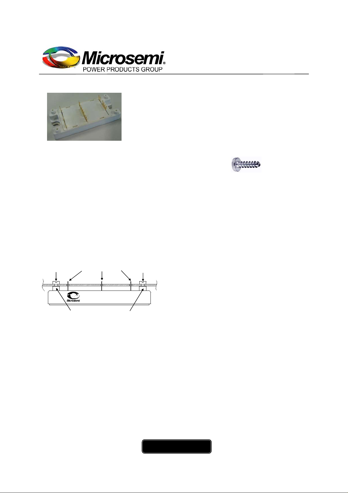
1. Power Module assembly onto PCB.
The PCB mounted on the SP4 power module can
be screwed onto the plastic post in order to
reduce all mechanical stress and minimize
relative movements on the pins which are
soldered onto the power module.
Plastite screw solderable pins plastite screw
SP4 POWER MODULE
plastic post plastic post
fig 1: PCB mounted on SP4 power module.
First, the PCB must be mounted onto the power
module and screwed onto the plastic posts (See
fig 1).
We recommend a self-tapering plastite screw
with a nominal diameter of 2.5 mm.
A plastite screw is a type of screw specifically
designed for use with plastic and other low
density materials. (See fig 2). The screw length
depends on the PCB thickness. With a 1.6 mm
(0.063”) thick PCB, use a plastite screw 6 mm
(0.25”) long. The maximum moun ting torque is
0.6Nm (5 lbf·in). In any case, the customer must
Application note
APT0501
December 2011
check the integrity of the plastic post after
screwing.
fig 2: example of plastite screw.
The second step consists of soldering all
electrical pins of the power module to the PCB.
Wave soldering or manual soldering processes
are recommended to solder the signal and power
terminals to the PCB. The standard wave
soldering temperature is 235°C (+/-5°C) for 5
seconds (+/- 1 second).
No-clean solder flux is required to attach the
PCB onto the module since aqueous module
cleaning is not allowed.
The PCB holes for module terminals should
have a diameter of 1.5mm
Do not reverse these two steps, because if all
pins are soldered first to the PCB, screwing the
PCB onto the plastic posts will create a
deformation of the PCB, leading to some
mechanical stress that can damage the tracks or
break the components on the PCB.
2. Power module mounting onto heat sink.
Proper mounting of the module base plate onto
the heat sink is essential to guarantee good heat
transfer. The heat sink and the power module
contact surface must be flat (recommended
flatness <50µm for 100mm continuous,
recommended roughness Rz 10) and clean (no
dirt, no corrosion, no damage) in order to avoid
mechanical stress when power module is
mounted, and to avoid an increase in thermal
resistance.
±0.1
for an easy fit.
www.microsemi.com
1/5
Page 2
2.1 Thermal grease application.
To achieve the lowest case to heat sink thermal
resistance, a thin layer of thermal grease must be
applied between the power module and the heat
sink. If the grease is applied onto the module
base plate, a minimum thickness of 60µm (2.4
mils) of grease should be applied with a roller or
a spatula.
If the grease is applied onto the heat sink, it is
recommended to use screen printing technique to
ensure a uniform deposition of a minimum
thickness of 60µm (2.4 mils). In any case, the
module bottom surface must be wetted
complete ly with thermal grease.
2.2 Mounting the power module onto th e
heat sink.
Place the power module above heat sink holes,
and apply a small pressure to it. Insert the M5
screw with lock and flat washers in each
mounting hole (a #10 screw can be used instead
of M5). The screw length must be at least 12 mm
(0.5”).
First lightly tighten the two mounting screws.
Tighten alternatively the screws until their final
torque value is reached (4.7 N.m max, or 3.5
lbf·ft).
Application note
APT0501
December 2011
It is recommended to use a screwdriver with
controlled torque for this operation.
If possible, screws can be tightened again after
three hours.
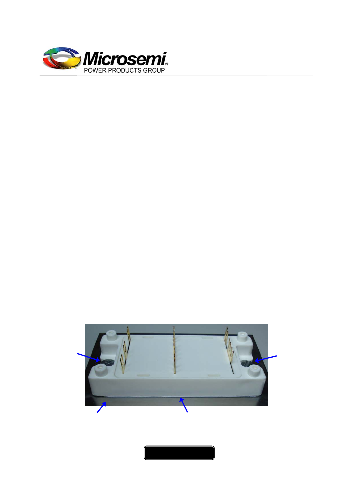
The quantity of thermal grease is correct when a
small amount of grease appears around the
power module once it is bolted down onto the
heat sink with the appropriate mounting torque
(see fig 3). Figure 4 shows the thermal grease on
the SP4 module base plate when removed from
the heat sink.
Note:
Holes in the PCB are necessary to insert
and tighten the mounting screws that attach the
power module to the heat sink. These access
holes must be large enough for the screw head
and washer to pass through freely, allowing for
normal variation in PCB hole location. (See fig
5).
M5 washers
& M5 screw
Heat sink Thermal grease flows out when screws are tightened
fig 3: Proper application of thermal grease to the power module.
www.microsemi.com
M5 washers
& M5 screw
2/5
Page 3

Application note
(4x)
APT0501
December 2011
fig 4: SP4 base plate with properly applied thermal grease after removal from heat sink.
3. Hole diameters in the PCB.
3.1 Top view.
Hole ∅ 2.9
±0.1
hole ∅ 1.5
pad ∅ 2.8
±0.1
±0.1
Heat sink
PCB
Hole ∅ 12.7
±0.1
(2x)
Fig 5: pad and hole diameters (in millimeters).
SP4 pinout can change according to the configuration (full bridge, boost chopper…). Each module
datasheet has specific hole location information.
www.microsemi.com
3/5
Page 4

Application note
k
APT0501
December 2011
3.2 Mounting example.
Figure 6 shows the top view of a PCB
mounted on an SP4 power module, and
both mounted on a heat sink. Note that the
fig 6: Power module assembly on heat sink and PCB.
4. Mounting instructions if using a large PCB.
If a large PCB is used, additional spacers
between the PCB and the heat sink are
necessary. It is recommended to keep a distance
of at least 5 cm between the power module and
access holes in the PCB allow plenty of
room for installing the module mounting
screws.
the spacers (see fig 7). The spacers must have
the same height as the plastic posts (17 mm
±0.5).
≥ 5cm
17mm ±0.5
SP4 POWER MODULE
Heat sin
≥ 5cm
Spacer Spacer
fig 7: Spacers used on large PCB.
www.microsemi.com
4/5
Page 5

k
5. Mounting instruction without using the plastic post.
For important temperature variations, extremely
low and high temperatures or strong shock and
vibration environment, screwing the PCB onto
the plastic posts is not recommended. The plastic
expansion leads to some mechanical stress that
can damage the tracks or the components on the
PCB.
PCB
SP4 POWER MODULE
18
±0.2
Spacer
mm
On the other hand, the plastic posts may break
under strong shock and vibration stress.
In order to avoid these phenomenons, the
utilization of metallic spacer 18
recommended to screw the PCB on top of the
power module. (See fig 8).
Application note
APT0501
December 2011
±0.2
mm high is
Spacer
Fig 8: PCB screwed onto the metallic spacers.
6. Connection push-pull forces.
When the PCB is mounted onto the power
module and the terminals soldered to it, some
mechanical forces may be applied to the
terminals. Such push or pull forces must not
exceed 10N (2.25lbf) maximum per individual
connector. This acceptable maximum value of
push-pull force may vary depending on the
mounting and operating conditions.
Heat sin
Conclusion:
This application note gives the main
recommendations regarding the mounting of SP4
modules. Applying these instructions will help
decreasing the mechanical stress both on PCB
and power module and therefore will ensure long
term operation of the system. Mounting
instructions to the heat sink must also be
followed to achieve the lowest thermal resistance
from the power chips down to the cooler. All
these operations are essential to guarantee the
best system reliability.
www.microsemi.com
5/5
 Loading...