

Page 1

SmartTime Static Timing Analyzer
User Guide
SmartFusion2, IGLOO2, RTG4, and PolarFire
NOTE: PDF files are intended to be viewed on the printed page; links and cross-references in this PDF file
may point to external files and generate an error when clicked. View the online help included with
software to enable all linked content.
Page 2

Page 3

SmartTime Static Timing Analyzer User Guide
Microsemi Corporate Headquarters
One Enterprise, Aliso Viejo,
CA 92656 USA
Within the USA: +1 (800) 713-4113
Outside the USA: +1 (949) 380-6100
Fax: +1 (949) 215-4996
Email:
sales.support@microsemi.com
www.microsemi.com
©2017 Microsemi Corporation. All
rights reserved. Microsemi and
the Microsemi logo are registered
trademarks of Microsemi
Corporation. All other trademarks
and service marks are the
property of their respective
owners.
Microsemi makes no warranty, representation, or guarantee regarding the information contained
herein or the suitability of its products and services for any particular purpose, nor does Microsemi
assume any liability whatsoever arising out of the application or use of any product or circuit. The
products sold hereunder and any other products sold by Microsemi have been subject to limited
testing and should not be used in conjunction with mission-critical equipment or applications. Any
performance specifications are believed to be reliable but are not verified, and Buyer must
conduct and complete all performance and other testing of the products, alone and together with,
or installed in, any end-products. Buyer shall not rely on any data and performance specifications
or parameters provided by Microsemi. It is the Buyer’s responsibility to independently determine
suitability of any products and to test and verify the same. The information provided by Microsemi
hereunder is provided “as is, where is” and with all faults, and the entire risk associated with such
information is entirely with the Buyer. Microsemi does not grant, explicitly or implicitly, to any party
any patent rights, licenses, or any other IP rights, whether with regard to such information itself or
anything described by such information. Information provided in this document is proprietary to
Microsemi, and Microsemi reserves the right to make any changes to the information in this
document or to any products and services at any time without notice.
About Microsemi
Microsemi Corporation (Nasdaq: MSCC) offers a comprehensive portfolio of semiconductor and
system solutions for aerospace & defense, communications, data center and industrial markets.
Products include high-performance and radiati on-hardened analog mixed-signal integrated
circuits, FPGAs, SoCs and ASICs; power management products; timing and synchronization
devices and precise time solutions, setting the world's standard for time; voice processing
devices; RF solutions; discrete components; enterprise storage and communication solutions;
security technologies and scalable anti-tamper products; Ethernet solutions; Power-over-Ethernet
ICs and midspans; as well as custom design capabilities and services. Microsemi is
headquartered in Aliso Viejo, California, and has approximately 4,800 employees globally. Learn
more at www.microsemi.com.
5-02-00560-6/01.17
3
Page 4

SmartTime Static Timing Analyzer User Guide
Table of Contents
About SmartTime (Enhanced Constraint Flow) ......................................................................... 7
Design Flows with SmartTime ................................................................................................... 9
Starting and Closing SmartTime - SmartFusion2, IGLOO2, RTG4, and PolarFire ................. 10
SmartTime Components .......................................................................................................... 10
Setting SmartTime Options - SmartFusion2, IGLOO2, RTG4, and PolarFire ......................... 11
SmartTime Toolbar .................................................................................................................. 13
SmartTime Timing Analyzer ..................................................................................................... 14
SmartTime Timing Analyzer ........................................................................ 15
Components of the SmartTime Timing Analyzer ..................................................................... 16
Analyzing Your Design ............................................................................................................. 17
Performing a Bottleneck Analysis ............................................................................................ 19
Managing Clock Domains ........................................................................................................ 21
Managing Path Sets ................................................................................................................. 22
Displaying Path List Timing Information................................................................................... 24
Displaying Expanded Path Timing Information ........................................................................ 26
Using Filters ............................................................................................................................. 28
Advanced Timing Analysis ......................................................................... 31
Understanding Inter-Clock Domain Analysis ........................................................................... 32
Activating Inter-Clock Domain Analysis ................................................................................... 33
Displaying Inter-Clock Domain Paths ...................................................................................... 34
Deactivating a Specific Inter-Clock Domain ............................................................................. 35
Changing Output Port Capacitance ......................................................................................... 36
Generating Timing Reports ......................................................................... 37
Types of Reports ...................................................................................................................... 38
Generating a Timing Report ..................................................................................................... 39
Understanding Timing Reports ................................................................................................ 40
Generating a Timing Violation Report ...................................................................................... 43
Understanding Timing Violation Reports ................................................................................. 44
Generating a Constraints Coverage Report ............................................................................ 46
Understanding Constraints Coverage Reports ........................................................................ 47
Generating a Bottleneck Report ............................................................................................... 49
Understanding Bottleneck Reports - SmartFusion2, IGLOO2, RTG4, and PolarFire ............. 50
Generating a Datasheet Report ............................................................................................... 52
Understanding Datasheet Reports ........................................................................................... 53
Generating a Combinational Loop Report ............................................................................... 55
Understanding Combinational Loop Reports ........................................................................... 56
Timing Concepts .......................................................................................... 57
4
Page 5

SmartTime Static Timing Analyzer User Guide
Static Timing Analysis Versus Dynamic Simulation ................................................................. 58
Timing Exceptions Overview .................................................................................................... 60
SmartTime Tutorials (Enhanced Constraints Flow) ................................................................. 67
Dialog Boxes ................................................................................................ 92
Add Path Analysis Set Dialog Box ........................................................................................... 93
Analysis Set Properties Dialog Box ......................................................................................... 95
Edit Filter Set Dialog Box ......................................................................................................... 96
Customize Analysis View Dialog Box ...................................................................................... 97
Manage Clock Domains Dialog Box ........................................................................................ 99
Set False Path Constraint Dialog Box.................................................................................... 100
SmartTime Options Dialog Box - SmartFusion2, IGLOO2, RTG4, and PolarFire ................. 102
Store Filter as Analysis Set Dialog Box ................................................................................. 105
Timing Bottleneck Analysis Options Dialog Box .................................................................... 106
Timing Datasheet Report Options Dialog Box ....................................................................... 110
Timing Report Options Dialog Box ......................................................................................... 111
Timing Violations Report Options Dialog Box ........................................................................ 115
Data Change History - SmartTime ............................................................ 117
Tcl Commands ........................................................................................... 118
create_set .............................................................................................................................. 119
expand_path .......................................................................................................................... 121
list_paths ................................................................................................................................ 123
remove_set ............................................................................................................................ 125
report ...................................................................................................................................... 126
save ........................................................................................................................................ 130
set_options (SmartFusion2, IGLOO2, RTG4, and PolarFire) ................................................ 131
Glossary ..................................................................................................... 134
5
Page 6

Page 7

SmartTime Static Timing Analyzer User Guide
About SmartTime (Enhanced Constraint Flow)
SmartTime is the Libero SoC gate-level static timing analysis tool. With SmartTime, you can perform
complete timing analysis of your design to ensure that you meet all timing constraints and that your design
operates at the desired speed with the right amount of margin across all operating conditions.
Note: SmartTime in the Enhanced Constraint Flow has changed. Creation and Editing of timing constraints
are now handled in a separate Timing Constraints Editor. See the Timing Constraints Editor
with creating and editing timing constraints in the Enhanced Constraints Flow.
Static Timing Analysis (STA)
Static timing analysis (STA) offers an efficient technique for identifying timing violations in your design and
ensuring that it meets all your timing requirements. You can communicate timing requirements and timing
exceptions to the system by setting timing constraints. A static timing analysis tool will then check and report
setup and hold violations as well as violations on specific path requirements.
STA is particularly well suited for traditional synchronous designs. The main advantage of STA is that unlike
dynamic simulation, it does not require input vectors. It covers all possible paths in the design and does all
the above with relatively low run-time requirements.
The major disadvantage of STA is that the STA tools do not automatically detect false paths in their
algorithms as it reports all possible paths, including false paths, in the design. False paths are timing paths
in the design that do not propagate a signal. To get a true and useful timing analysis, you need to identify
those false paths, if any, as false path constraints to the STA tool and exclude them from timing
considerations.
The SmartTime user interface provides effici ent, us er -friendly ways to define these critical false paths.
for help
Timing Constraints
SmartTime supports a range of timing constraints to provide useful analysis and efficient timing-driven
layout.
Timing Analysis
SmartTime provides a selection of analysis types that enable you to:
• Find the minimum clock period/highest frequency that does not result in a timing violations
• Identify paths with timing violations
• Analyze delays of paths that have no timing constraints
• Perform inter-clock domain timing verification
• Perform maximum and minimum delay analysis for setup and hold checks
To improve the accuracy of the results, SmartTime evaluates clock skew during timing analysis by
individually computing clock insertion delays for each register.
SmartTime checks the timing requirements for violations while evaluating timing exceptions (such as
multicycle or false paths).
SmartTime and Place and Route
Because Libero SoC Place and Route uses SmartTime STA during timing-driven place-and-route in the
background; your analysis and place and route constraints are always consistent.
SmartTime and Timing Reports
From SmartTime > Tools > Reports, the following report files can be generated:
• Timing Report (for both Max and Min Delay Analysis)
• Timing Violations Report (for both Max and Min Delay Analysis)
• Bottleneck Report
• Constraints Coverage Report
• Combinational Loop Report
7
Page 8

SmartTime Static Timing Analyzer User Guide
SmartTime and Cross-Probing into Chip Planner
From SmartTime, you can select a design object and cross-probe the same design object in Chip Planner.
Design objects that can be cross-probed from SmartTime to Chip Planner include:
• Ports
• Macros
• Timing Paths
SmartTime and Cross-Probing into Constraints Editor
From SmartTime, you can cross-probe into the Constraints Editor. Select a Timing Path in SmartTime’s
Analysis View and add a Timing Exception Constraint (False Path, Multicycle Path, Max Delay, Min Delay) .
The Constraint Editor reflects the newly added timing exception constraint.
The Constraints Editor must be running for Cross-Probing to work.
See Also
Starting and Closi ng SmartTime
Components of SmartTime Timing Analyzer
Changing SmartTime Preferences
8
Page 9

SmartTime Static Timing Analyzer User Guide
Design Flows with SmartTime
You can access SmartTime in Libero SoC either implicitly or explic itly during the following phases of design
implementation:
• During Place and Route – When you select timing-dri ven place-and-route, SmartTime runs in the
background to provide accurate timing information.
• After Place and Route – Run S martT ime to per for m post-layout timing analysis and adjust timing
constraints. In the Libero SoC Design Flow window, expand Implement Design > Verify Post-Layout
Implementation. You can:
• Double-click Verify Timing to generate Timing Reports.
• Right-click Open SmartTime > Open Interactively to run SmartTime.
• During Back-Annotation – SmartTime runs in the background to generate the SDF file for timing
simulation.
You can also run SmartTime whenever you need to generate timing reports, regardless of which design
implementation phase you are in.
See Libero SoC for Enhanced Constraint Flow
Annotation.
for more information about Place and Route and Back-
9
Page 10

SmartTime Static Timing Analyzer User Guide
Starting and Closing SmartTime - SmartFusion2, IGLOO2, RTG4, and
PolarFire
You must have completed Place and Route for your design before using SmartTime interactively. If your
design has not yet been placed-and-routed, Libero SoC will complete that phase prior to starting SmartTime.
To open SmartTime interactively, in Implement Design > Verify Post Layout Implementation right-click
Open SmartTime > Open Interactively.
SmartTime reads your design and displays post- or pre-layout timing information.
To close SmartTime, from the File menu, choose Exit.
SmartTime Components
• The Maximum Delay Analysis View and the Minimum Delay Analysi s View enable you to
analyze your design
With SmartTime, you can:
• Browse through your design’s various clock domains to examine the timing paths and identify those
that violate your timing requirements
• Create customizable timing report s
• Navigate directly to the paths responsible for violating your timing requirements
10
Page 11
SmartTime Static Timing Analyzer User Guide
Setting SmartTime Options - SmartFusion2, IGLOO2, RTG4, and
PolarFire
You can modify SmartTime options for timing anal ysis by using the SmartTime Options dialog box.
To set SmartTime options:
1. From the SmartTime Maximum/Minimum Delay Analysis View window, choose Tools> Options.
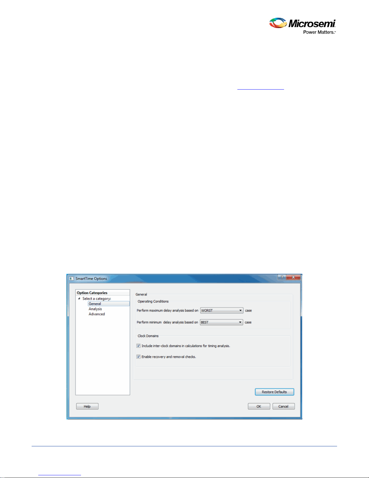
The SmartTime Options dialog box has three categories: General, Analysis and Advanced.
2. In the General category, select the settings for the operating conditions. SmartTime performs
maximum or minimum delay analysis based on the Best, Typical, or Worst case.
3. Check or uncheck whether you want SmartTime to use inter-clock domains in calculations for timing
analysis.
4. Click Restore Defaults only if you want the settings in the General pane to revert to their default
settings.
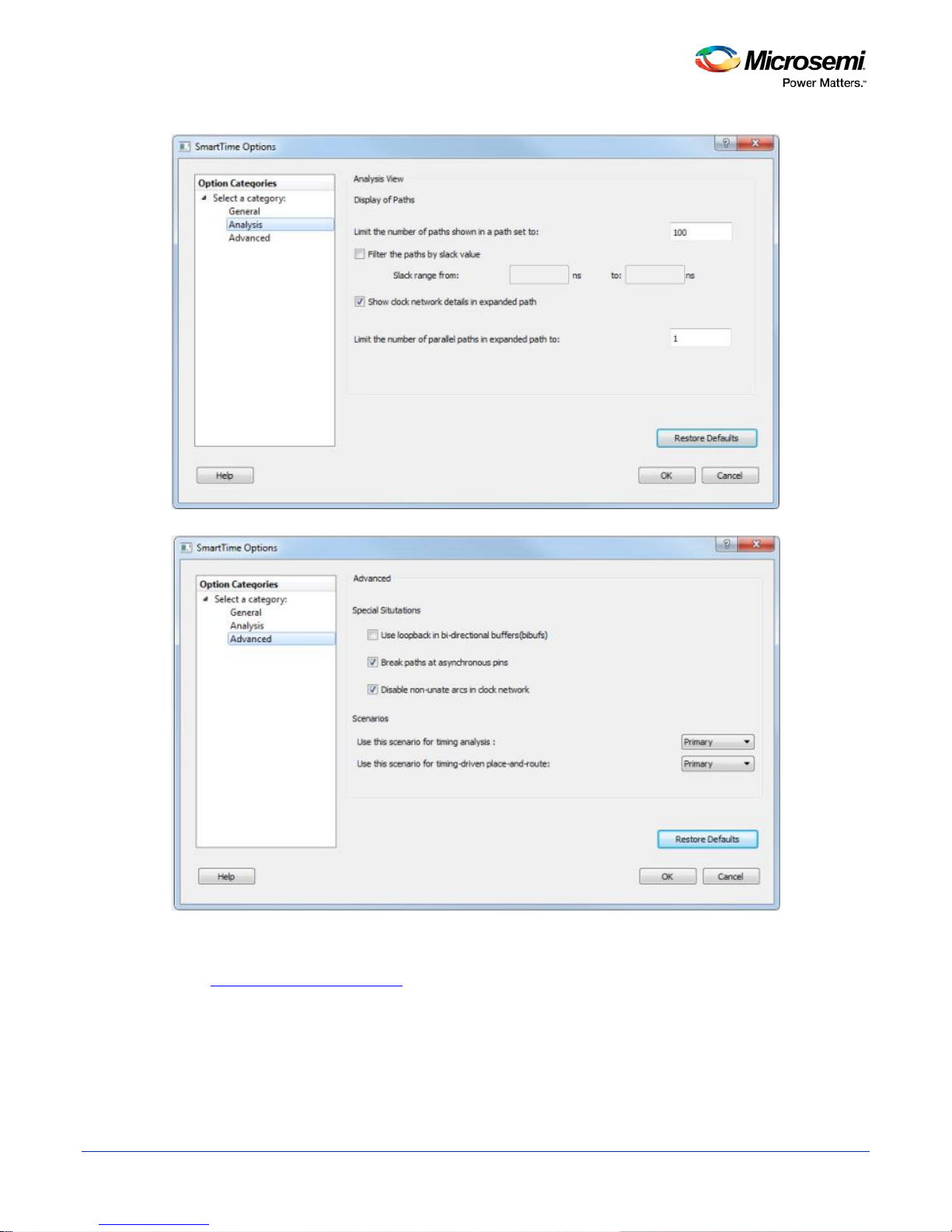
5. Click Analysis to display the options you can modify in the Analysis view.
6. Enter a number greater than 1 to specify the maximum number of paths to include in a path set during
timing analysis.
7. Check or uncheck whether to filter the paths by slack value. If you check this box, you must then
specify the slack range between minimum slack and maximum slack.
8. Check or uncheck whether to include clock network deta ils .
9. Enter a number greater than 1 to specify the number of parallel paths in the expanded path.
10. Click Restore Defaults only if you want the settings in the Analysis View pane to revert to their default
settings.
11. Click Advanced to display advanced options.
12. Check or uncheck whether to use loopback in bidirectional buffers (bibufs) and/or break paths at
asynchronous pins. Check or uncheck whether to disable non-unate arc s in the clock path.
13. Click Restore Defaults only if you want the settings in the Advanced pane to revert to their default
settings.
14. Click OK.
Figure 1 · SmartTime Options Dial og Box – General Options
11
Page 12
SmartTime Static Timing Analyzer User Guide
Figure 2 · SmartTime Options Dial og Box – Analysis Options
Figure 3 · SmartTime Options Dial og Box – Advanced Options
See Also
SmartTime Options Dialog Box
12
Page 13
SmartTime Static Timing Analyzer User Guide
Icon
Description
constraints editor
the constraints editor
the constraints editor
analysis view
analysis view
manager
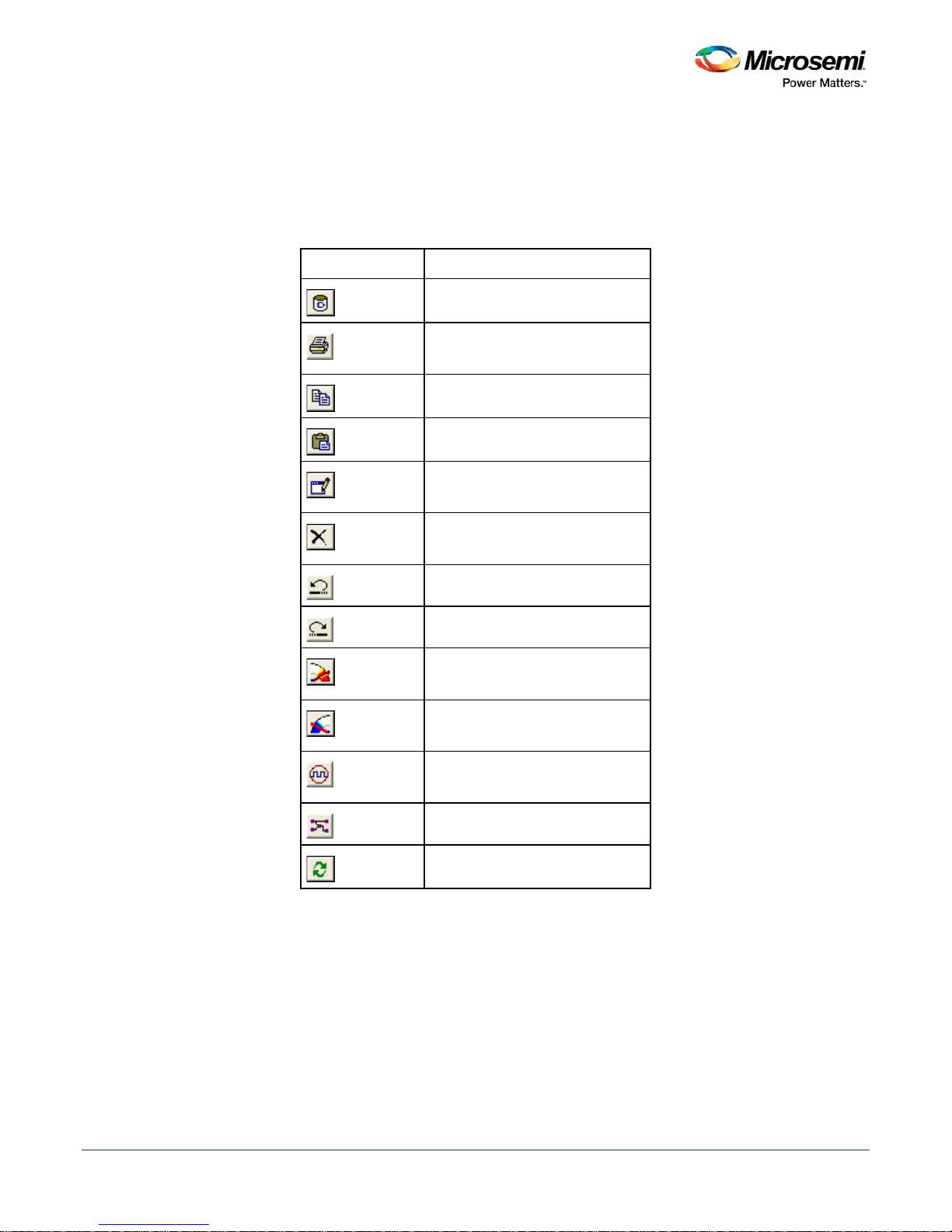
SmartTime Toolbar
The SmartTime toolbar contains commands for constraining or analyzing designs. Tool tips are available for
each button.
Table 1 · SmartTime Toolbar
Commits the changes
Prints the contents of the
Copies data to the clipboard
Pastes data from the clipboard
Modifies the selected object from
Deletes the selected object from
Undoes previous changes
Redoes previous changes
Opens the maximum delay
Opens the minimum delay
Opens the manage clock domains
13
Opens the path set manager
Recalculates all
Page 14

SmartTime Static Timing Analyzer User Guide
SmartTime Timing Analyzer
The SmartTime Timing Analyzer is an interactive Static Timing Analysis tool. Click Open SmartTime in the
Design Flow Window to invoke the SmartTime Timing Analyzer (Design Flow Window > Open SmartTime
> Open Interactively).
14
Page 15

SmartTime Static Timing Analyzer User Guide
SmartTime Timi ng A nalyzer
15
Page 16
SmartTime Static Timing Analyzer User Guide
Components of the SmartTime Timing Analyzer
Use the SmartTime Timing Analyzer to visualize and identify timing issues in your design for the selected
scenario. In this view, you can evaluate how far you are from meeting your timing requirements, create
custom sets to track, set timing exceptions to obtain timing closure, and cross-probe paths with other tools.
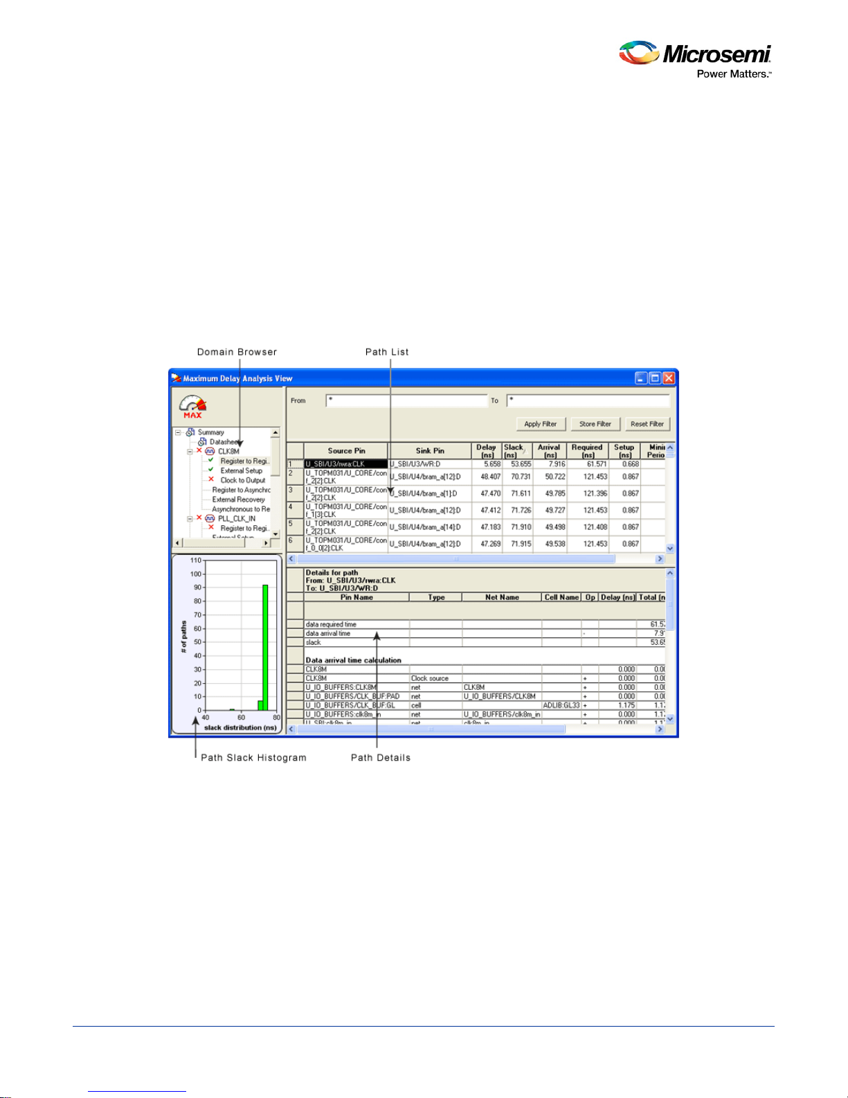
The timing analysis view includes:
• Domain Browser: Enables you to perform your timing analysis on a per domain basis.
• Path List: Displays paths in a specific set in a given domain sorted by slack.
• Path Details: Displays detailed timing analysis of a selected path in the paths list.
• Analysis View Filter: Enables you to filter the content of the paths list.
• Path Slack Histogram: When a set is selected in the Domain Browser, the Path Slack Histogram
displays a distribution of the path slacks for that set. Selecting one or multiple bars in the Path Slack
Histogram filters the paths displayed in the Path List.
You can copy, change the resolution and the number of bars of the chart from the right-click menu.
Figure 4 · SmartTime Timing Analyzer Components
16
Page 17
SmartTime Static Timing Analyzer User Guide
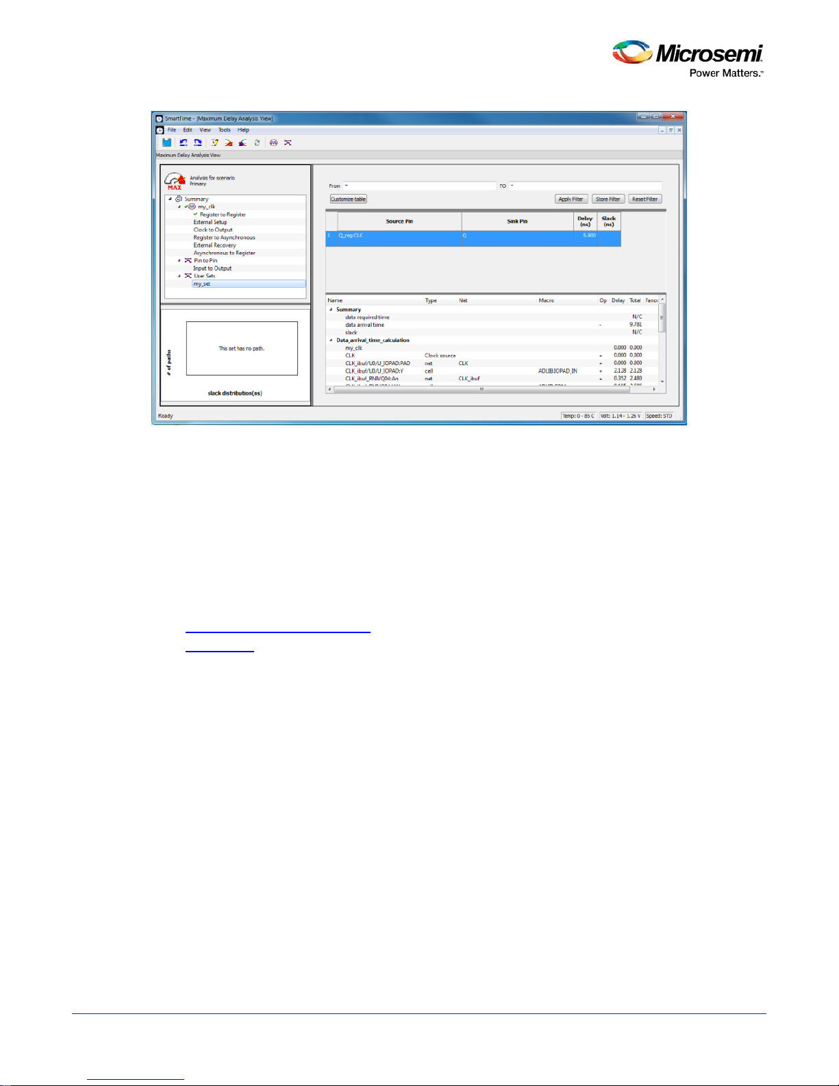
Analyzing Your Design
The timing engine uses the following priorities when analyzing paths and calculating slack:
1. False path
2. Max/Min delay
3. Multi-cycle path
4. Clock
If multiple constraints of the same priority apply to a path, the timing engine uses the tightest constraint.
You can perform two types of timing analysis: Maximum Delay Analysis and Minimum Delay Analysis.
To perform the basic timing analysis:
1. Open the Timing Analysis View using one of the following methods:
• In the Design Flow window, click the Timing Analyzer icon to display the
SmartTime Timing Analyzer.
• From the Sm artTime Tools menu, choose Timing Analyzer > Maximum
Delay Analysis or Minimum Delay Analysis.
• Click the icon for Maximum Delay Analysis or the icon for Minimum
Delay Analysis from the SmartTime window.
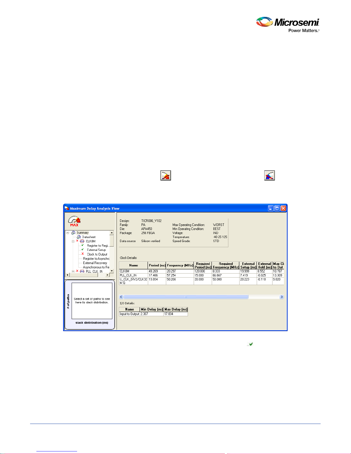
Note: When you open the Timing Analyzer from Designer, the Maximum Delay Analysis window is
displayed by default.
2. In the Domain Browser, select the clock domain. Clock domains with a indicate that the timing
requirements in these domains were met. Clock domains with an x indicate that there are vi olations
within these domains. The Paths List displays the timing paths sorted by slack. The path with the
lowest slack (biggest violation) is at the top of the list.
3. Select the path to view. The Path Details below the Paths List displays detailed information on how the
slack was computed by detailing the arrival time and required time calculation. When a path is
violated, the slack is negative and is displayed in red color.
4. Double-click the path to display a separate view that includes the path details and schematic.
17
Figure 5 · Maximum Delay Analysis View
Page 18

SmartTime Static Timing Analyzer User Guide
Note: In cases where the minimum pulse width of one element on the critical path limits the maximum
frequency for the clock, SmartTime displays an icon for the clock name in the Summary List.
Click on the icon to display the name of the pin that limits the clock frequency.
5. Repeat the above steps as required.
18
Page 19
SmartTime Static Timing Analyzer User Guide
Performing a Bottleneck Analysis
To perform a bottleneck analysis
1. From SmartTime’s Max/Min Delay Analysis View, select Tools > Bottleneck Analysis. The Timing
Bottleneck Analysis Options dialog box appears.
2. Select the options you wish to display for bottleneck information and click OK.
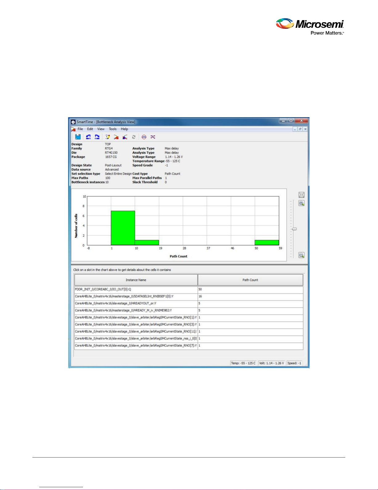
The Bottleneck Analysis View appears in a separate window (see image below).
A bottleneck is a point in the design that contributes to multiple timing violations. The Bottleneck Analysis
View contains two sections:
• Device Description
• Bottleneck Description
Device Description
The device section contains general information about the design and the parameters that define the
bottleneck computation:
19
Figure 6 · Bottleneck Analysis View
Page 20

SmartTime Static Timing Analyzer User Guide
• Design name
• Family
• Die
• Package
• Design state
• Data source
• Set selection type
• Max paths
• Bottleneck instances
• Analysis type
• Analysis max case
• Voltage
• Temperature
• Speed grade
• Cost type
• Max parallel paths
• Slack threshold
Bottleneck Description
This section displays a graphic representation of the bottleneck analy s is and li sts the core o f the bottl ene ck
information for the bar selected in the chart above. If no bar is selected, the grid lists all bottleneck
information.
Click the controls on the right to zoom in or out the contents in the chart.
Right-click the chart to export the chart or to copy the chart to the clipboard.
The list is divided into two columns:
• Instance name: refers to the output pin name of the instan ce .
• Bottleneck cost: displays the pin's cost giv en the cho sen cost type. Pin names are lis ted in decre asi ng
order of their cost type.
See Also
Timing Bottleneck Analysis Options dialog box (SmartTime)
20
Page 21
SmartTime Static Timing Analyzer User Guide
Managing Clock Domains
In SmartTime, timing paths are organized by clock domains. By default, SmartTime displays domains with
explicit clocks. Each clock domain includes at least three path sets:
• Register to Register
• External Setup (in the Maximum Analysis View) or External Hold (in the Minimum Analysis View)
• Clock to Out
You must select a path set to display a list of paths in that specific set.
To manage the clock domains:
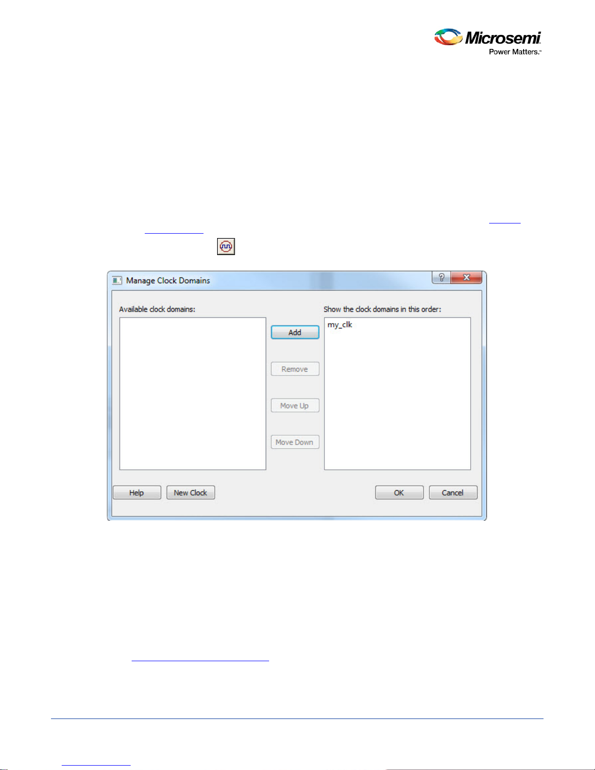
1. Right-click anywhere in the Domain Browser, and choose Manage Clock Domains. The
Clock Domains dialog box appears (as shown below).
Tip: You can click the icon in the Sm artTime window bar to display the Manage Clock Domains
dialog box.
Manage
2. To add a new domain, select a clock domain from the Available clock domains list, and click either
Add or New Clock to add a non-explicit clock domain.
3. To remove a displayed domain, select a clock domain from the Show the clock domainin this order
list, and click Remove.
4. To change the display order in the Domain Browser, select a clock domain from the Show the clock
domainin this order list, and then use the Move Up or Move Down to change the order in the list.
5. Click OK. SmartTime updates the Domain Browser based on your specifications. If you have added a
new clock domain, then it will include at least the three path sets as mentioned above.
See Also
Manage Clock Domains Dialog Box
21
Figure 7 · Manage Clock Domains Dialog Box
Page 22
SmartTime Static Timing Analyzer User Guide
Managing Path Sets
You can create and manage custom path sets for timing analysis and tracking purposes. Path sets are
displayed under the Custom Path Sets at the bottom of the Domain Browser.
To add a new path set:
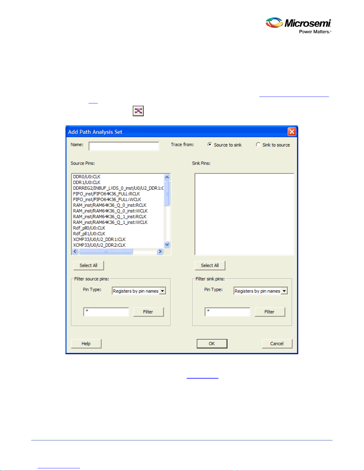
1. Right-click anywhere in the Domain Browser, and choose Add Set. The Add Path Analysis Set Dialog
Box dialog box appears (as shown below).
Tip: You can click the icon in the Sm artTime window bar to display the Add Path Analysis Set
dialog box.
2. Enter a name for the path set.
3. Select the source and sink pins. You can use the filters
4. Click OK. The new path set appears under Custom Path Sets in the Domain Browser (as shown
below).
22
Figure 8 · Add Path Analysis Set Dialog Box
to control the type of pins displayed.
Page 23
SmartTime Static Timing Analyzer User Guide
Figure 9 · Updated Domain Browser with User Sets
To remove an existing path set:
1. Select the path set from the User Sets in the Domain Browser.
2. Right-click the set to delete, and then choose Delete Set from the right-click menu.
To rename an existing path set:
1. Select the path set from User Set in the Domain Browser.
2. Right-click the set to rename, and then choose Rename Set from the right-click menu.
3. Edit the name directly in the Domain Browser.
See Also
Add Path Analysis Set Dialog Box
Using Filters
23
Page 24
SmartTime Static Timing Analyzer User Guide
Displaying Path List Timing Information
The Path List in the Timing Analysis View displays the timing information required to verify the timing
requirements and identify violating paths. The Path List is organized in a grid where each row represents a
timing path with the corresponding timing information displayed in columns. Timing information is
customizable; you can add or remove columns for each type of set.
By default, each type of set displays a subset of columns as follows:
• Register to Register: Source Pin, Sink Pin, Del ay, Slack, Arrival, Required, Setup, Minimum Period,
and Skew.
• External Setup: Source Pin, Sink Pin, Delay, Slack, Arrival, Required, Setup, and External Setup.
• Clock to Out: Source Pin, Sink Pin, Delay, Slack, Arrival, Required, and Clock to Out.
• Input to Output: Source Pin, Sink Pin, Delay, and Slack.
• Custom Path Sets: Source Pin, Sink Pin, Delay, and Slack.
You can add the following columns for each type of set:
• Register to Register: Clock, Source Clock Edge, Destination Clock Edge, Logic Stage Count, Max
Fanout, Clock Constraint, Maximum Delay Constraint, and Multicycle Constraint.
• External Setup: Clock, Destination Clock Edge, Logic Stage Count, Max Fanout, Clock Constraint,
Input Delay Constraint, Required External Setup, Maximum Delay Constraint, and Multicycle
Constraint.
• Clock to Out: Clock, Source Clock Edge, Logic Stage Count, Max Fanout, Clock Constraint, Output
Delay Constraint, Required Maximum Clock to Out, Maximum Delay Constraint, and Multicycle
Constraint.
• Input to Output: Arrival, Required, Setup, Hold, Logic Stage Count, and Max Fanout.
• Custom Path Sets.
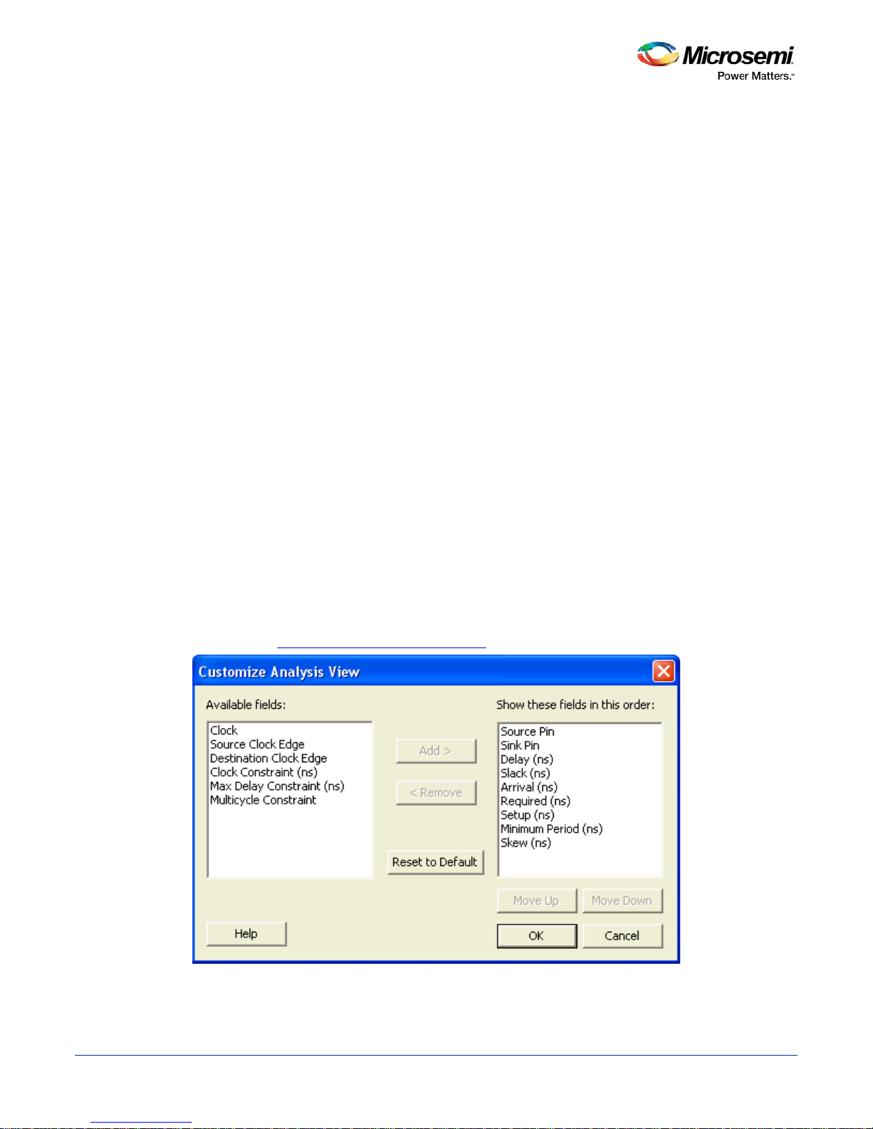
To customize the set of timing information in the Path List:
1. Select the set to customize.
2. Select the whole Paths List by clicking in the upper-left corner .
3. Right-click anywhere on the column headings, and then choose Customize table from the right-click
menu. The Customize Analysis View Dialog Box
dialog box appears (as shown below).
4. To add one or more columns, select the fields to add from the Available fields list, and click Add.
24
Figure 10 · Customize Analysis View Dialog Box
Page 25

SmartTime Static Timing Analyzer User Guide
5. To remove one or more columns, select the fields to remove from the Show these fields in this order
list, and click Remove.
6. Click OK to add or remove the selected columns. SmartTime updates the Timing Analysis View.
See Also
Customize Analysis View
25
Page 26
SmartTime Static Timing Analyzer User Guide
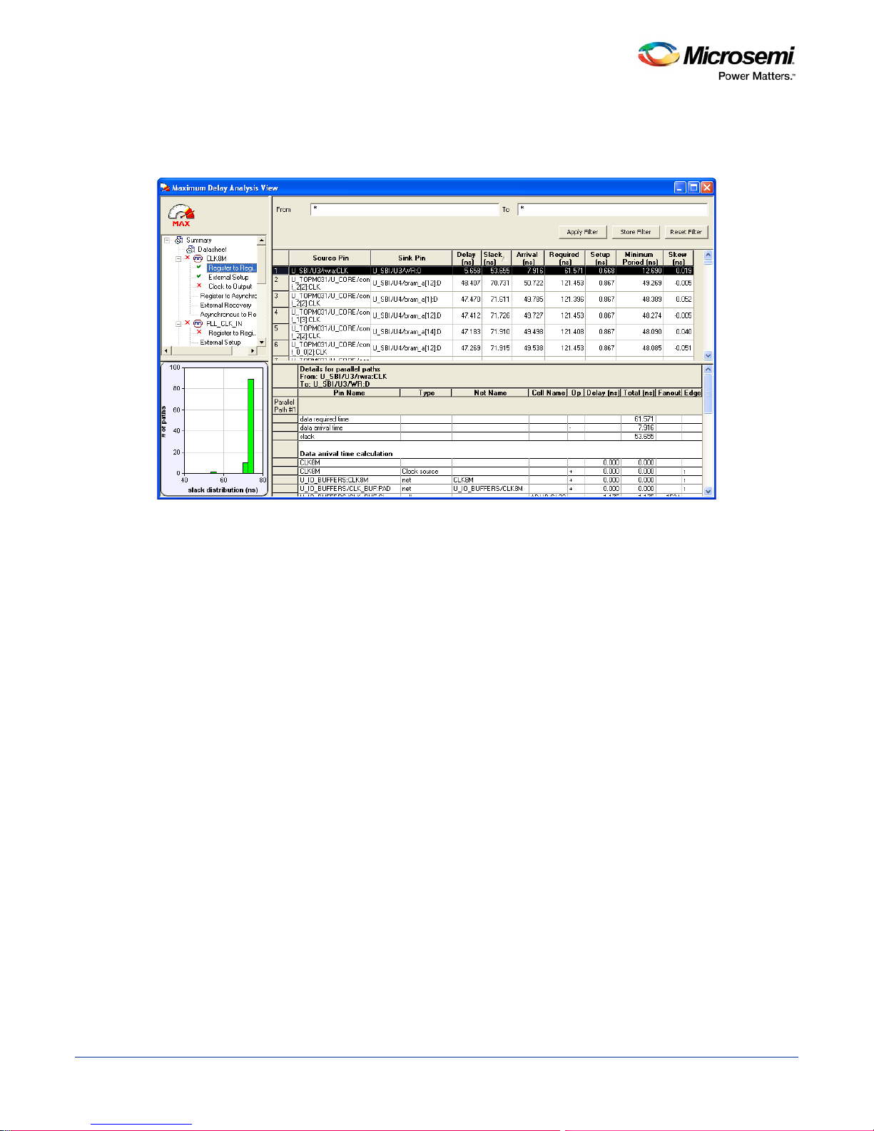
Displaying Expanded Path Timing Information
SmartTime displays the list of paths and the path details for all parallel paths.
Figure 11 · Expanded Path View
The Path List displays all parallel paths in your design. The Path Details grid displays the path details for all
parallel paths.
To display the Expanded Path View:
From the Path List: double-click the path, or right-click a path and select expand selected paths.
From the Expanded Path View: double-click the path, or right -click the path and se lect expand path.
26
Page 27
SmartTime Static Timing Analyzer User Guide
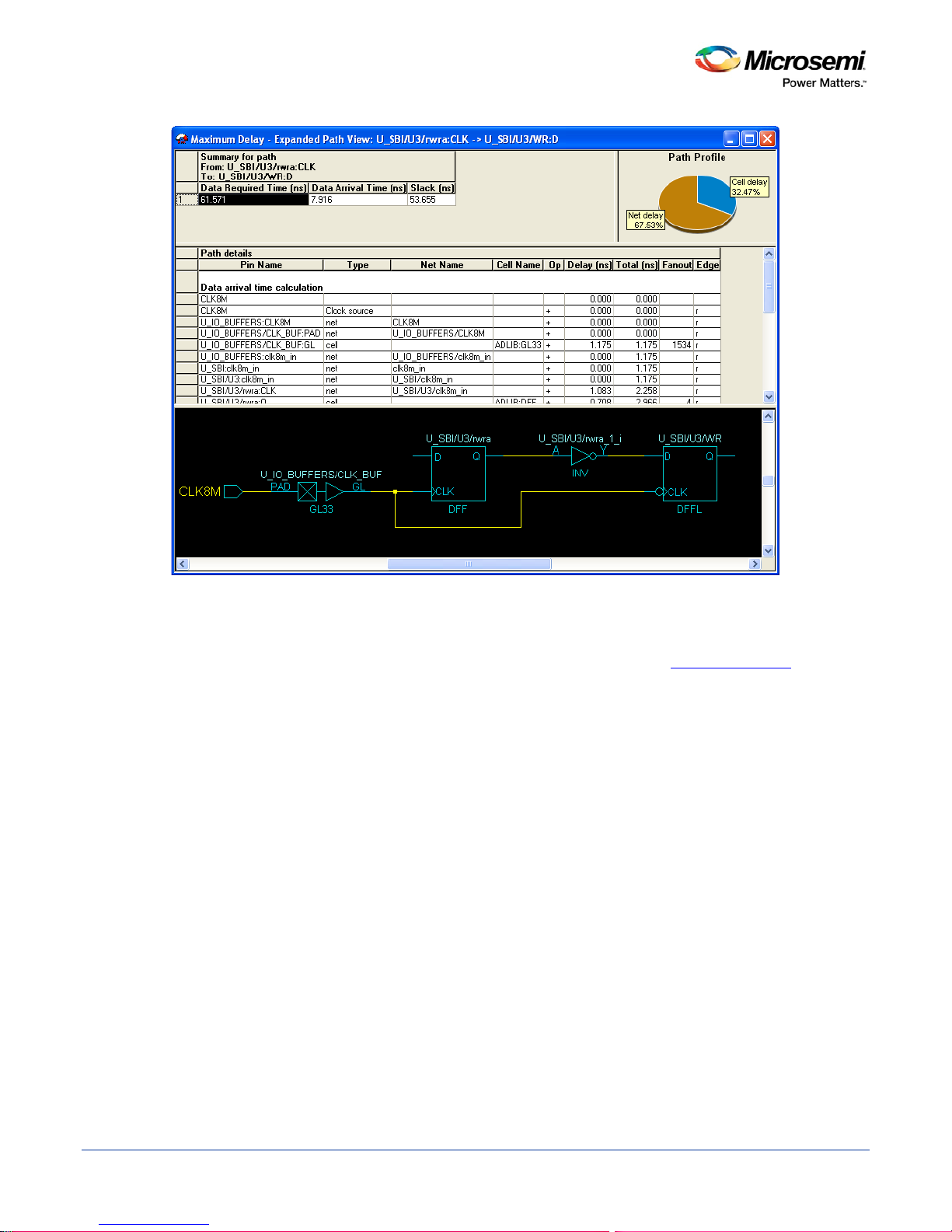
Figure 12 · Expanded Path View
The Expanded Path Summary provides a summary of all parallel paths for the selected path. The Path
Profile chart displays the percentage of time taken by cells and nets for the selected path. If no parallel path
is selected in this view, the Path Profile shows the percentage for all paths. By default, SmartTime only
shows one path for each Expanded Path. You can change this default in the SmartTime Options
dialog box.
The Expanded Path View also includes a schematic of the path and a path profile chart for the paths
selected in the Expanded Path Summary.
27
Page 28
SmartTime Static Timing Analyzer User Guide
Using Filters
You can use filters in SmartTime to limit the Path List content (that is, create a filtered list on the source and
sink pin names). The filtering options appear on the top of the Timing Analysis View. You can save these
filters one level below the set under which it has been created.
To use the filter:
1. Select a set in the Domain Browser to display a given number of paths, depending on your
Options settings (100 paths by default).
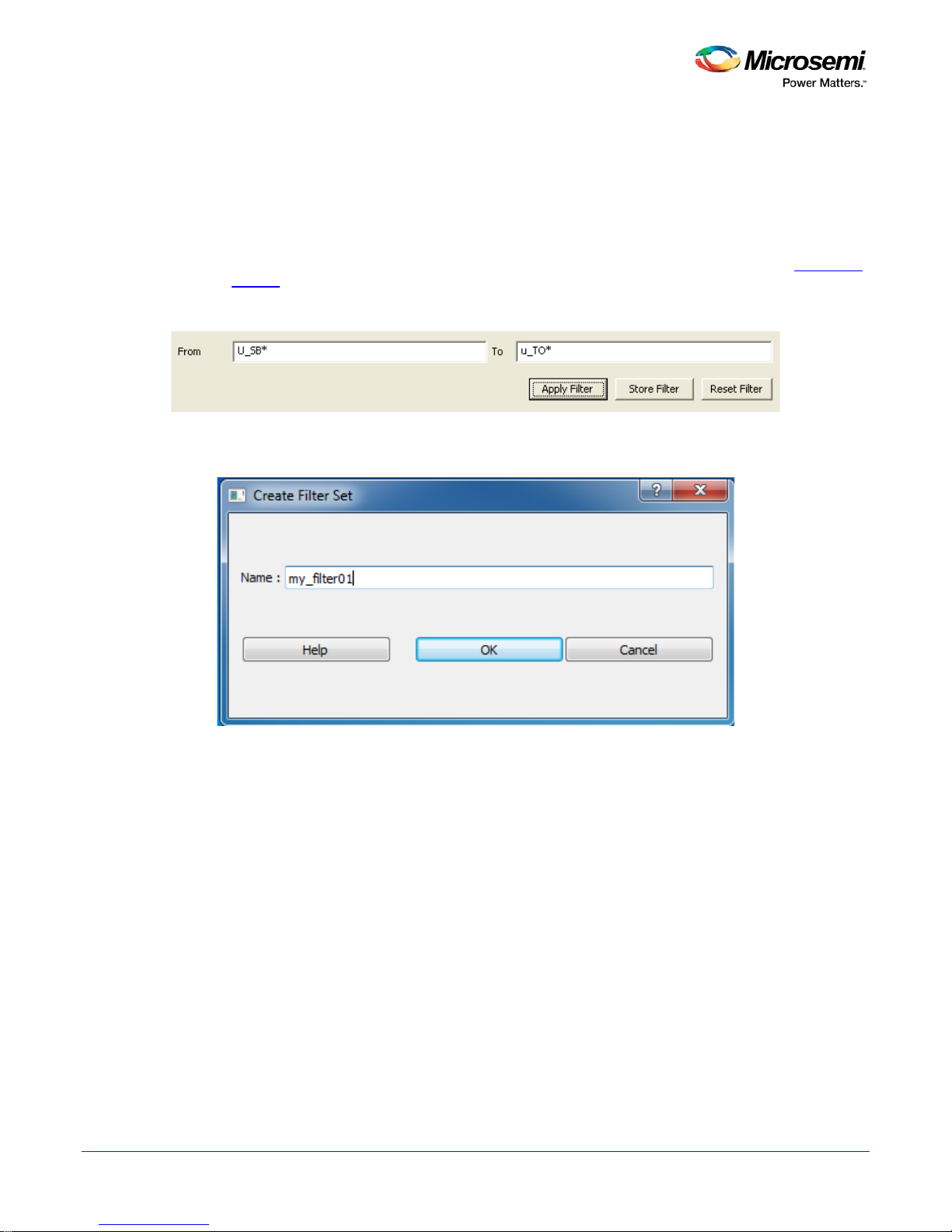
2. Enter the filter criteria in both the From and To fields and click Apply Filter. This limits the display to
the paths that match your filter criteria.
Figure 13 · Maximum Delay Analysis View
3. Click Store Filter to save your filter criteria with a special name. The Create Filter Set dialog box
appears (as shown below).
SmartTime
Figure 14 · Create Filter Set Dialog Box
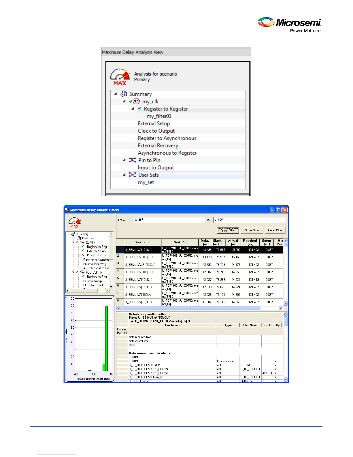
4. Enter a name for the filter, such as myfilter01, and click OK. Your new filter name appears below the
set under which it was created.
28
Page 29
SmartTime Static Timing Analyzer User Guide
Figure 15 · my_filter01
Figure 16 · Updated Maximum Delay Analysis View
Repeat the above steps and cascade as many sets as you need using the filtering mechanism.
29
Page 30

SmartTime Static Timing Analyzer User Guide
To remove a set created with filters:
1. Select the set that uses filters.
2. Right-click the set, and choose Delete Set from the shortcut menu.
To rename a set created with filters:
1. Select the set that uses filters.
2. Right-click the set, and choose Rename Set from the shortcut menu.
3. Edit the name directly in the Domain Browser.
To edit a specific filter in the set:
1. Select the filter to edit.
2. Right-click the filter, and choose Edit Set from the shortcut menu.
See Also
SmartTime Options
Store Filter as Analysis Set
Edit Set dialog box
30
Page 31

SmartTime Static Timing Analyzer User Guide
Advanced Timing Analysis
31
Page 32

SmartTime Static Timing Analyzer User Guide
Understanding Inter-Clock Domain Analysis
When functional paths exist across two clock domains (the register launching the data and the one capturing
it are clocked by two different clock sources), you must provide accurate specification of both clocks to allow
a valid inter-clock domain timing check. This is important especially when the clocks are specified with
different waveforms and frequencies.
When you specify multiple clocks in your design, the first step is to consider whether the inter-clock domain
paths are false or functional. If these paths are functional, then you must perform setup and hold checks
between the clock domains in SmartTime. Unless specified otherwise, SmartTime considers the inter-clock
domain as false, and therefore does not perform setup or hold checks between the clock domains.
If you have several clock domains that are subset of a single clock (such as if you want to measure clock
tree delay from an input clock to a generated clock), you must configure Generated Clock Constraints for
each of the clock domains in order for SmartTime to do execute the calculation and show timing for each of
the inter-clock-dom ain path s.
Once you include the inter-clock domains for timing analysis, SmartTime analyzes for each inter-clock
domain the relationship between all the active clock edges over a common period equal to the least
common multiple of the two clock periods. The new common period represents a full repeating cycle (or
pattern) of the two clock waveforms (as shown below).
For setup check, SmartTime considers the tightest relation launch-capture to ensure that the data arrives
before the capture edge. The hold check verifies that a setup relationship is not overwritten by a following
data launch.
Figure 17 · Example Showing Inter-Clock Domains
See Also
Activating inter-clock domain analysis
Deactivating a specific inter-clock domain
Displaying inter-clock domain pat h s
32
Page 33

SmartTime Static Timing Analyzer User Guide
Activating Inter-Clock Domain Analysis
To activate the inter-clo c k domain chec king:
1. In SmartTime, from the Tools menu choose Options. The SmartTime Options Dialog Box dialog box
appears (as shown below).
2. In the general category, check the Include inter-clock domains in calculations for timing analysis.
Figure 18 · SmartTime Options Dialo g Box
3. Click OK to save the dialog box settings.
See Also
Inter-Clock Domain Analysis
Deactivating a Specific Inter-Clock Domain
Displaying Inter-Clock Domain Paths
33
Page 34

SmartTime Static Timing Analyzer User Guide
Displaying Inter-Clock Domain Paths
Once you activate the inter-clock domain checking for a gi ven clock domain CK1, SmartTime automatically
detects all other domains CKn with paths ending at CK1. SmartTime creates inter-clock domain sets CKn to
CK1 under the domain CK1. Each of these sets enables you to display the inter-clock domain p aths
between a given clock domain and CK1.
To display an inter-clock domain set:
1. Expand the receiving clock domain of the inter-clock domain in the Domain Browser to display its
related sets. For the inter-clock domain CK1 to CK2, expand clock domain CK2.
2. Select the inter-clock domain that you want to see expanded from these sets. Once selected, all paths
between the related two domains are displayed in Paths List in the same way as any register to
register set.
See Also
Inter-Clock Domain Analysis
Activating Inter-Clock Domain Analy si s
Deactivating a Specific Inter-Clock Domain
34
Figure 19 · Maximum Delay Analysis View
Page 35

SmartTime Static Timing Analyzer User Guide
Deactivating a Specific Inter-Clock Domain
To deactivate the inter-clock domain checking for the specific clock domains clk2->clk1, without
disabling this option for the other clock domains:
1. From the Tools menu, choose Constraints Editor to open the Constraints Editor View.
2. In the Constraints Browser, double-click False Path under Exceptions. The Set False Path Constraint
dialog box appears.
3. Click the Browse button to the right of the From text box. The Select Source Pins for False Path
Constraint dialog box appears.
4. For Specify pins, select by keyword and wildcard.
5. For Pin Type, select Registers by clock names from the Pin Type drop-down list.
6. Type the inter-clock domain name, for example Clk2, in the filter box and click Filter.
7. Click OK to begin filtering the pins by your criteria. In this example, [get_clocks {Clk2}] appears in the
From text box in the Set False Path Constraint
8. Repeat steps 3 to 7 for the To option in the Set False Path Constraint dialog box, and type Clk2 in the
filter box.
9. Click OK to validate the new false path and display it in the Paths List of the Constraints Editor.
10. Click the Recalculate All button in the toolbar.
11. Select the inter-clock domain set clk2 -> clk1 in the Domain Browser (as shown below).
12. Verify that the set does not contain any paths.
dialog box.
See Also
Inter-Clock Domain Analysis
Activating Inter-Clock Domain Analysis
Displaying Inter-Clock Domain Paths
Set False Path Constraint Dialog Box
35
Figure 20 · Maximum Delay Analysis View
Page 36

SmartTime Static Timing Analyzer User Guide
Changing Output Port Capacitance
Output propagation delay is affected by both the capacitive loading on the board and the I/O standard. The
I/O Attribute Editor in ChipPlanner provides a mechanism for setting the expected capacitance to improve
the propagation delay model. SmartTime automatically uses the modified delay model for delay calculations.
To change the output port capacitance and view the effect of this change in SmartTime Timing Analyzer,
refer to the following example. The figure below shows the delay from FF3 to output port OUT2. It shows a
delay of 6.603 ns based on the default loading of 35 pF.
Figure 21 · Maximum Delay Analysis View
If your board has output capacitance of 75pf on OUT2, you must perform the following steps to update the
timing number:
1. Open the I/O Attribute Editor and change the output load to 75pf.
Figure 22 · I/O Attribute Editor View
2. Select File > Save.
3. Select File > Close.
4. Open the SmartTime Timing Analyzer.
You can see that the Clock to Output delay changed to 7.723 ns.
36
Page 37

SmartTime Static Timing Analyzer User Guide
Generating Timing Reports
37
Page 38

SmartTime Static Timing Analyzer User Guide
Types of Reports
Using SmartTime you can generate the following types of reports:
• Timer report – This report displays the timing information organized by clock domain.
• Timing Violati ons report – This flat slack report provides information about constraint violations.
• Bottleneck report – This report displays the points in the design that contribute to the most
timing violations.
• Datasheet report – This report describes the characteristics of the pins, I/O technologies, and timing
properties in the design.
• Constraints Coverage report – This report displays the overall cov erag e of the tim ing con strai nts set
on the current design.
• Combinational Loop report – This report displays loops found during initialization.
See Also
Generating a Timing Report
Generating a Timing Violation Report
Generating a datasheet report
Generating a bottleneck report
Generating a constraints coverage report
Generating a Combinational Loop Report
38
Page 39

SmartTime Static Timing Analyzer User Guide
Generating a Timing Report
The timing report enables you to quickly determine if any timing problems exist in your design. The
Maximum Delay Analysis timing report lists the following information about your design:
• Maximum delay from input I/O to output I/O
• Maximum delay from input I/O to internal registers
• Maximum delay from internal registers to output I/O
• Maximum delays for each clock network
• Maximum delays for interactions between clock networks
To generate a timing report:
1. From the SmartTime Max/Min Delay Analysis View, choose Reports > Timer. The
Options Dialog Box appears.
2. Select the options you want to include in the report, and then click OK.
The timing report appears in a separate window.
See Also
Understanding Timing Reports
Timing Report Options Dialog Box
Timing Report
39
Page 40

SmartTime Static Timing Analyzer User Guide
Understanding Timing Reports
The timing report cont ain s the follow ing se ctio ns.
Header
The header lists:
• The report type
• The version of Designer used to generate the report
• The date and time the report was generated
• General design information (name, fam ily , etc.)
Summary
The summary section reports the timing information for each clock domain.
By default, the clock domains reported are the explicit clock domains that are shown in SmartTime. You can
filter the domains and get only specific sections in the report (see Timing Report Options Dialog Box
Path Sections
The paths section lists the timing information for different types of paths in the design. This section is
reported by default. You can deselect this option in the Timing Report Options Dialog Box
By default, the number of paths displayed per set is 5.
You can filter the domains using the Timing Report Options dialog box.
You can also view the stored filter sets in the generated report using the timing report options. The filter sets
are listed by name in their appropriate section, and the number of paths reported for the filter set is the same
as for the main sets.
By default, the filter sets are not reported.
).
.
Clock domains
The paths are organized by clock domain.
Register to Register set
This set reports the paths from the registers clock pins to the registers data pins in the current clock domain.
External Setup set
This set reports the paths from the top level design input ports to the registers in the current clock domain.
Clock to output set
This set reports the paths from the registers clock pins to the top level design output ports in the current
clock domain.
Register to Asynchronous set
This set reports the paths from registers to asynchronous control signals (like asynchronous set/reset).
External Recovery set
This set reports the external recovery check timing for asynchronous control signals (l ike a sy nchro nou s
set/reset).
Asynchronous to Register set
This set reports the paths from asynchronous control signals (like asynchronous set/reset) to registers.
40
Page 41

SmartTime Static Timing Analyzer User Guide
Inter-clock domain
This set reports the paths from the registers clock pins of the specified clock domain to the registers data
pins in the current clock domain. Inter-domain paths are not reported by default.
Pin to pin
This set lists input to output paths and user sets. Input to output paths are reported by default. To see the
user-defined sets, use the Timing Report Options Dialog Box
Input to output set
This set reports the paths from the top level design input ports to top level design output ports.
Expanded Paths
Expanded paths can be reported for each set. By default, the number of expanded paths to report is set to 1.
You can select and change the number when you specify Timing Report Options
.
.
41
Page 42

SmartTime Static Timing Analyzer User Guide
See Also
Generating a Timing Report
Timing Report Options Dialog Box
42
Figure 23 · Timing Report
Page 43

SmartTime Static Timing Analyzer User Guide
Generating a Timing Violation Report
The timing violations report provides a flat slack report centered around constraint violations.
To generate a timing violation report
1. From the SmartTime Max/Min Delay Analysis View window, choose Tools > Reports > Timing
Violations. The Timing Violations Report Options Dialog Box
2. Select the options you want to include in the report, and then click OK. The timing violations report
appears in a separate window.
See Also
Understanding Timing Violation Reports
appears.
43
Page 44

SmartTime Static Timing Analyzer User Guide
Understanding Timing Violation Reports
The timing violation report contains the following sections:
Header
The header lists:
• The report type
• The version of Designer used to generate the report
• The date and time the report was generated
• General design information (name, fam ily , etc.)
Paths
The paths section lists the timing information for the violated paths in the design.
The number of paths displayed is controlled by two parameters:
• A maximum slack threshold to report
• A maximum number or path to report
By default, the slack threshold is 0 and the number of paths is limited. The default maximum number of
paths reported is 100.
All clocks domains are mixed in this report. The paths are listed by decreasing slack.
You can also choose to expand one or more paths. By default, no paths are expanded. For details, see the
timing violation report options.
44
Page 45

SmartTime Static Timing Analyzer User Guide
Figure 24 · Timing Violations Report
See Also
Generating a Timing Violation Report
Timing Violations Report Options Dialog Box
45
Page 46

SmartTime Static Timing Analyzer User Guide
Generating a Constraints Coverage Report
The constraints coverage report contains information about the constraints in the design.
To generate a constraints coverage report, from the SmartTime Max/Min Delay Analysis View, choose
Tools > Reports > Constraints Coverage. The report appears in a separate window.
See Also
Understanding Constraints Coverage Reports
46
Page 47

SmartTime Static Timing Analyzer User Guide
Understanding Constraints Coverage Reports
The constraint coverage displays the overall coverage of the timing constraints set on the current design.
You can generate this report either from within Designer or within SmartTime Analyzer. The report contains
three sections:
• Coverage Summary
• Results by Clock Domain
• Enhancement Suggestions
Coverage Summary
The coverage summary gives statistical information on the timing constraint in the design. For each type of
timing checks (Setup, Recovery, Output, Hold and Removal), it specifies how many are Met (there is a
47
Figure 25 · Constraints Coverage Report
Page 48

SmartTime Static Timing Analyzer User Guide
constraint and it is satisfied), Violated (there is a constraint and it is not satisfied), or Untested (no constraint
was found).
Clock Domain
This section provides a coverage summary for each clock domain.
Enhancement Suggestions
The enhancement suggestion reports, per clock domain, a list of constraints that can be added to the design
to improve the coverage. It also reports if some options impacting the coverage can be changed.
Detailed Stats
This section provides detailed suggestions regarding specific clocks or I/O ports that may require to be
constrained for every pin/port that requires checks.
Setting SmartTime Options
48
Page 49

SmartTime Static Timing Analyzer User Guide
Generating a Bottleneck Report
The bottleneck report provides a list of the bottlenecks in the design.
To generate a bottleneck report, from the,SmartTime Max/Min Delay Analysis View, choose Tools >
Reports > Bottleneck. The report appears in a separate window.
See Also
Understanding Bottleneck Reports
Timing Bottleneck Analysis Options Dialog Box
49
Page 50

SmartTime Static Timing Analyzer User Guide
Understanding Bottleneck Reports - SmartFusion2, IGL OO2, RTG4, and
PolarFire
A bottleneck is a point in the design that contributes to multiple timing violations. The purpose of the
bottleneck report is to provide a list of the bottlen ec ks in the design. You can gener at e thi s report eit h er fro m
SmartTime Analyzer. It contains two sections
• Device Description
• Bottleneck Analysis
Figure 26 · Bottleneck Report
The bottleneck can only be computed if and only a cost type is defined. There are two options available:
• Path count: This cost type associates the severity of the bottleneck to the count of violating/critical
paths that traverse the instance.
• Path cost: This cost type associates the severity of the bottleneck to the sum of the timing violations
for the violating/critical paths that traverse the instance.
Device Description
The device section contains general information about the design, including:
• Design name
• Family
• Die
• Package
• Software version
Bottleneck Analysis
This section lists the core of the bottleneck information. It is divided into two columns:
50
Page 51

SmartTime Static Timing Analyzer User Guide
• Instance name: refers to the output pin name of the instan ce .
• Path Count: Displays the number of violating paths which include the instance pin.
See Also
Timing Bottleneck Analysis Options Dialog Box
51
Page 52

SmartTime Static Timing Analyzer User Guide
Generating a Datasheet Report
The datasheet reports information about the external characteristics of the design.
To generate a datasheet report, from the SmartTime Max/Min Delay Analysis View, choose Tools >
Reports > Datasheet. The report appears in a separate window.
See Also
Understanding Datasheet Reports
Timing Datasheet Report Options Dialog Box
52
Page 53

SmartTime Static Timing Analyzer User Guide
Understanding Datasheet Reports
The datasheet report displays the external characteristics of the design. . You can generate this report from
SmartTime Max/Min Delay Analysis View. It contains three tables:
• Pin Description
• DC Electrical Characteristics
• AC Electrical Characteristics
Pin Description
Provides the port name in the netlist, location on the package, type of port, and I/O technology assigned to
it. Types can be input, output, inout, or clock. Clock ports are ports shown as "clock" in the Clock domain
browser.
DC Electrical Characteristics
Provides the parameters of the different I/O technologies used in the design. The number of parameters
displayed depends on the family for which you have created the design.
53
Figure 27 · Datasheet Report
Page 54

SmartTime Static Timing Analyzer User Guide
AC Electrical Characteristics
Provides the timing properties of the ports of the design. For each clock, this section includes the maximum
frequency. For each input, it includes the external setup, external hold, external recovery, and external
removal for every clock where it applies. For each output, it includes the clock-to-out propagation time. This
section also displays the input-to-output propagation time for combinational paths.
See Also
Generating a Datasheet Report
Timing Datasheet Report Options Dialog Box
54
Page 55

SmartTime Static Timing Analyzer User Guide
Generating a Combinational Loop Report
The combinational loop report displays all loops found during initialization and reports pins associated with
the loop(s), and the location where the loop is broken.
To generate the combinational loop report; from the Tools menu, choose Reports > Combinational Loops
....
Select either the Plain Text or Comma Separated Values option in the Combinational_Loops Report
Options dialog box and click OK.
The plain text report will pop up in a new window; you will be prompted to save the CSV in a direc tory of
your choosing.
See Also
Understanding Combinat iona l Loop Re port s
55
Page 56

SmartTime Static Timing Analyzer User Guide
Understanding Combinational Loop Reports
The combinational loop report displays all loops found during initialization and reports pins associated with
the loop(s), and the location where the loop is broken.
See Also
Generating a Combinational Loop Report
56
Figure 28 · Combinational Loop Report
Page 57

SmartTime Static Timing Analyzer User Guide
Timing Concepts
57
Page 58

SmartTime Static Timing Analyzer User Guide
Static Timing Analysis Versus Dynamic Simulation
Static timing analysis (STA) offers an efficient technique for identifying timing violations in your design and
ensuring that it meets all your timing requirements. You can communicate timing requirements and timing
exceptions to the system by setting timing constraints. A static timing analysis tool will then check and report
setup and hold violations as well as violations on specific path requirements.
STA is particularly well suited for traditional synchronous designs. The main advantage of STA is that unlike
dynamic simulation, it does not require input vectors. It covers all possible paths in the design and does all
the above with relatively low run-time requirements. The major disadvantage of STA is that the STA tools do
not automatically detect false paths in their algorithms.
Delay Models
The first step in timing analysis is the computation of single component delays. These components could be
either a combinational gate or block or a single interconnect connecting two components.
Gates that are part of the library are pre-characterized with delays under different parameters, such as inputslew rates or capacitive loads. Traditional models provide delays between each pair of I/Os of the gate and
between rising and falling edges.
The accuracy with which interconnect delays are computed depends on the design phase. These can be
estimated using a simple Wire Load Model (WLM) at the pre-layout phase, or a more complex Resistor and
Capacitor (RC) tree solver at the post-layout phase.
Tim ing Path T ypes
Path delays are computed by adding delay values across a chain of gates and interconnects. SmartTime
uses this information to check for timing violations. Traditionally, timing paths are presented by static timing
analysis tools in four categories or "sets":
• Paths between sequential components internal to the design. SmartTime displays this category under
the Register to Register s et of each displayed clock domain.
• Paths that start at input ports and end at sequential components internal to the design. SmartTime
displays this category under the External Setup and External Hold sets of each displayed clock
domain.
• Paths that start at sequential components internal to the design and end at output ports. SmartTime
displays this category under the Clock to Out set of each displayed clock domain.
• Paths that start at input ports and end at output ports. Smar tT ime dis play s this category under the
Input to Output set.
Maximum Clock Frequency
Generally, you set clock constraints on clocks for which you have a specified requirement. The absence of
violations indicates that this clock will be able to run at least at the specified frequency. However, in the
absence of such requirements, you may still be interested in computing the maximum frequency of a specific
clock domain.
To obtain the maximum clock frequency, a static timing analysis tool computes the minimum period for each
path between two sequential elements. To compute the maximum period, the tool evaluates the maximum
data path delay and the minimum skew between the two elements, as well as the setup on the receiving
sequential element. It also considers the polarity of each sequential element. The maxim um frequency is the
inverse of the largest value among the maxim um period of all the paths in the clock domain. The path
responsible for limiting the frequency of a given clock is called the critical path.
Setup Check
The setup and hold check ensures that the design functions as specified at the required clock frequency.
58
Page 59

SmartTime Static Timing Analyzer User Guide
Setup check specifies when data is required to be present at the input of a sequential component in order for
the clock to capture this data effectively into the component. Timing analyzers evaluate the setup check as a
maximum timing budget allowed between adjacent sequential elements. For more details on how setup
check is processed, refer to Arrival Time, Required Time, and Slack
See Also
Static Timing Analysis Versus Dynamic Simulation
Arrival Time, Required Time, and Slack
Arrival Time, Required Time and Slack
You can use arrival time and required time to verify timing requirements in the presence of constraints.
Below is a simple example applied to verifying the clock requirement for setup between sequential elements
in the design.
The arrival time represents the time at which the data arrives at the input of the receiving sequential
element. In this example, the arrival time is considered from the setup launch edge at CK, taken as a time
reference (instant zero). It follows the clock network along the blue line until the clock pin on FF1 (delay d1).
Then it continues along the data path always following the blue line until the data pin D on FF2. Therefore,
Arrival_Time
The required time represents when the data is required to be present at the same pin FF2:D. Assume in this
example that in the presence of an FF with the same polarity, the capturing edge is simply one cycle
following the launch edge. Using the period T provided to the tool through the clock constraint, the event
gets propagated through the clock network along the red line until the clock pin of FF2 (delay d3). Taking
into account FF2 setup (delay d4), this means that the clock con strai nt re quire s the data t o be presen t d4
time before the capturing clock edge on FF2. Therefore, the required time is:
Required_Time
The slack is simply the difference between the required time and arrival time:
Slack
FF2:D
If the slack is negative, the path is violating the setup relationship between the two sequential elements.
= d1 + d2
FF2:D
= T + d3 - d4
FF2:D
= Required_Time
- Arrival_Time
FF2:D
FF2:D
.
Figure 29 · Arrival Time and Required Time for Setup Check
59
Page 60

SmartTime Static Timing Analyzer User Guide
Timing Exceptions Overview
Use timing exceptions to overwrite the default behavior of the design path. Timing exceptions include:
• Setting multicycle constrai nt to specify paths that (by design) will take more than one cycle.
• Setting a false path constraint to identify paths that must not be included in the timing analysis or the
optimization flow.
• Setting a maximum delay constraint on specific paths to relax or to tighten the original cl oc k con strai nt
requirement.
Clock Skew
The clock skew between two different sequential components is the difference between the insertion delays
from the clock source to the clock pins of these components. SmartTime calculates the arrival time at the
clock pin of each sequential component. Then it subtracts the arrival time at the receiving component from
the arrival time at the launching component to obtain an accurate clock skew.
Both setup and hold checks must account for clock skew. However, for setup check, SmartTime looks for
the smallest skew. This skew is computed by using the maximum insertion delay to the launching sequential
component and the shortest insertion delay to the receiving component.
For hold check, SmartTime looks for the largest skew. This skew is computed by using the shortest insertion
delay to the launching sequential component and the largest insertion delay to the receiving component.
SmartTime makes this distinction automatically.
Cross Probing
Design objects displayed in S martT ime ca n be cross-probed into other Libero SoC tools. Libero SoC allows
cross-probing from SmartTime to the Constraints Editor (but not vice versa) and from SmartTime to Chip
Planner (but not vice versa). When cross-probing from SmartTime to one of the other tools, both SmartTime
and the other tool must first be opened.
From SmartTime to Constraint Editor
You can add a timing exception constraint from SmartTime and have the Constraints Editor display the
Constraint. From the SmartTime Maximum or Minimum Delay Analysis View, click a timing path to add a
timing exception constraint. When the Constraints Editor’s Add Constraint dialog box opens, the fields for
source (from) pin and destination (to) pin are populated with the correct names from the timing path you
have selected.
To add a timing exception constraint from a timing path in SmartTime Max/Min Delay Analysis View:
1. Open SmartTime (Design Flow Window > Verify Timing > Open interactively).
2. Open the Constraints Editor (Constraint Manager > Timing Tab > Edit with Constraints Editor).
3. Select Max/Min Delay Analysis View and right-click a timing path in the table.
4. Select a timing exception constraint to add: False Path Constraint, Maximum Delay Constraint,
Minimum Delay Constraint, or Multicycle Path Constraint.
60
Page 61

SmartTime Static Timing Analyzer User Guide
Figure 30 · Add Timing Constraint from SmartTi m e’s Reported Timing Path
Note: The Add Max/Min Delay, False Path, and Multicycle Path Constraint menu items are grayed out if the
Constraint Editor is not open.
Add the Constraint in the Add Constraint dialog box. Note that the source/from pin and destination/to pin
field are populated with the correct pin names captured from the SmartTime reported path (Source Pin and
Sink Pin) you have clicked.
61
Page 62

SmartTime Static Timing Analyzer User Guide
Figure 31 · Add Maximum Delay Constraint
5. Click OK to exit the Add Cons traint Dialog box.
6. Click Save in the Constraints Editor.
7. Exit the Constraints Editor.
8. Exit SmartTime.
9. Rerun Place and Route if the newly-added constraint that is added to a file (the Target file) is used for
Place and Route and Verify Timing.
10. Open SmartTime Maximum/Minimum Delay Analysis View.
From SmartTime to Chip Planner
Cross-probing allows you to select a design object in one application and display the selected object in
another application. Because Libero SoC allows you to cross-probe design objects from SmartTime to Chip
Planner, you can better understand how the two applications interact with each other. With cross-probing, a
timing path not meeting timing requireme nts can be fix ed w ith relativ e ease w hen you see th e less-thanoptimal placement of the design object (in terms of timing requirements) in Chip Planner. Cross-probing from
SmartTime to Chip Planner is available for the following design objects:
• Macros
• Ports
• Nets/Paths
Note: Cross-probing of design objects is available from SmartTime to Chip Planner but not vice versa.
Before you can cross-probe from SmartTime to Chip Planner, you must:
1. Complete the Place and Route step on the design.
2. Open both SmartTime and Chip Planner.
62
Page 63

SmartTime Static Timing Analyzer User Guide
Cross-Probing Examples
To cross-probe from SmartTime to Chip Planner, a design macro in SmartTime is used.
Design Macro Example
1. Make sure that the design has successfully completed the Place and Route step.
2. Open SmartTime Maximum/Minimum Analysis View.
3. Open Chip Planner.
4. In the SmartTime Maximum Analysis View, right-click the instance Q[2] in the Timing Path Graph and
choose Show in Chip Planner. Note that with cross-probing , the Q[2] macro is se lect ed in Chip
Planner’s Logical View and highlighted (white) in the Chip Canvas. The Properties window in Chip
Planner displays the properties of Q[2].
Note: Show in Chip Planner is grayed out if Chip Planner is not already open.
Note: You may need to zoom in to view the highlighted Q2 Macro in the Chip Canvas.
Figure 32 · Cross-Probing – Macro
Timing Path Example
1. Make sure that the design has successfully completed the Place and Route step.
2. Open the SmartTime Maximum/Minimum Analysis View.
3. Open Chip Planner.
4. In the SmartTime Maximum/Minimum Analysis View, right-click the net CLK_ibuf/U0/U_IOPAD:PAD in
the Table and choose Show Path in Chip Planner. Note that the net is selected (highlighted in red) in
the Chip Canvas view and the three macros connected to the net are also highlighted (whi te) in the
Chip Canvas view.
Note: Show Path in Chip Planner is grayed out if Chip Planner is not already open.
63
Page 64

SmartTime Static Timing Analyzer User Guide
Figure 33 · Cross-Probing – Timing Path
Alternatively, right-click a path in the Max/Min Delay Analysis View and select Show Path in Chip Planner
to cross-probe the path.
Figure 34 · Cross-Probing Path from Max/Min Delay Analysis View Table
Port Example
1. Make sure that the design has successfully completed the Place and Route step.
2. Open the SmartTime Maximum/Minimum Analysis View.
3. Open Chip Planner.
4. In the SmartTime Maximum/Minimum Analysis View, right-click the Port “CLK” in the Path and choose
Show in Chip Planner. Note that the Port “CLK” is selected and highlighted in the Chip Planner Port
View.
Note: Show in Chip Planner is grayed out if Chip Planner is not already open.
64
Page 65

SmartTime Static Timing Analyzer User Guide
Figure 35 · Cross-Probing – Port
From the Properties View inside Chip Planner, you will find useful information about the Port “CLK” you are
cross-probing:
• Port Type
• Port Placement Location (X-Y coordinates)
• I/O Bank Number
• I/O Standard
• Pin Assignment
65
Figure 36 · Properties View of Port “CLK”
Page 66

SmartTime Static Timing Analyzer User Guide
66
Page 67

SmartTime Static Timing Analyzer User Guide
SmartTime Tutorials (Enhanced Constraints Flow)
Tutorial 1 - 32-Bit Shift Register with Clock Enable
This tutorial section describes how to enter a clock constraint for the 32-bit shift register shown. You will use
the SmartTime Constraints Editor and perform post-layout timing analysis using the SmartTime Timing
Analyzer.
Figure 37 · 32-bit Shift Register
Use the links below to go directly to a topic:
• Add a Clock Constraint
• Run Place and Route
• Maximum Delay Analysis with Timing Analyzer
• Minimum Delay Analysis with Timing Analyzer
• Changing Constraints and Observing Results
To set up your project:
1. Invoke Libero SoC. From the Project menu, choose New Project.
2. Enter shift32 for your new project name and browse to a folder for your project location.
3. Select Verilog as the Preferred HDL Type.
4. Leave all other settings at the default values.
67
Page 68

SmartTime Static Timing Analyzer User Guide
Figure 38 · New Project Creation - 32 Bit Shift Register
5. Click Next to go to Device Selection page. Make the following selection from the pull-down menu:
• Family: SmartFusion2
• Die: M2S090TS
• Package: 484FBGA
• Speed:STD
• Core Voltage: 1.2 V
• Range: COM
6. Click the M2S090TS-1FG484 part number and click Next.
7. Accept the default settings in the Device Settings page and click Next.
8. Accept the default settings in the Design Template page and click Next.
68
Page 69

SmartTime Static Timing Analyzer User Guide
9. In the Add HDL source files page, click Import file to import the source file, Navigate to the location of
the source Verilog file for the 32-bit shift register you have downloaded from the Microsemi website
Click to select the source file and click Open. After project creation, the source Verilog file you import
will appear in the project’s hdl folder under the File tab.
.
10. Click Next to go to the Add Constraints Page.
11. We are not adding any constraints. Click Finish to exit the New Project Creation wizard.
12. Click Use Enhanced Constraint Flow in the New Project Informat ion dialog box.
Figure 39 · New Project Information Dialog Box
13. After you have created the project, confirm that the imported Verilog source file appears in the Files
window, as shown in the figure below.
69
Page 70

SmartTime Static Timing Analyzer User Guide
Figure 40 · HDL File shift_reg32.v in the Libero SoC File Window
14. Confirm that the shift_reg32 design appears in the Design Hierarchy window, as shown in the figure
below.
70
Page 71

SmartTime Static Timing Analyzer User Guide
Figure 41 · shift_reg32 in the Design Hierarchy Window
15. In the Design Flow window, double-click Synthesize to run Synplify Pro with default settings. A green
check marks appears next to Synthesize when Synthesis is successful (as shown in the figure below).
71
Page 72

SmartTime Static Timing Analyzer User Guide
Figure 42 · Synthesis and Compile Complete - 32-Bit Shift Register with Clock Enable
Add a Clock Constraint - 32 Bit Shift Register
To add a clock constraint to your design:
1. In the Design Flow window, double-click Manage Constraints. The Constraint Manager appears (as
shown in the figure below.)
2. Click the Timing tab.
72
Figure 43 · Constraint Manager
Page 73

SmartTime Static Timing Analyzer User Guide
3. Click Edit with Constraints Editor > Edit Place and Route Constraints. The Constraints Editor
appears.
Figure 44 · Constraints Editor – Add clock constraint
4. In the Constraints Editor, right-click Clock under Requirement and select Add Clock Constraint.
The Create Clock Constraint Dialog Box appears.
5. From the Clock Source drop-down menu, choose the CLK pin.
6. Enter my_clk in the Clock Name field.
7. Set the Frequency to 250 MHz (as shown in the figure below) and leave all other values at the default
settings. Click OK to continue.
73
Figure 45 · Create Clock Constraint Dialog Box
Page 74

SmartTime Static Timing Analyzer User Guide
Figure 46 · Add a 250 MHz Clock Constraint
The clock constraint appears in the SmartTime Constraints Editor (as shown in the figure below).
Figure 47 · 250 MHz Clock Constraint in the Constraint Editor
8. From the File menu, choose Save to save the constraints.
9. From the SmartTime File menu, choose Exit to exit SmartT ime. Lib ero creat es a const raint file to
store the clock constraint. This file is listed and displayed in the Constraint Manager. It is named
user.sdc and is designated as Target.
Note: A target file is used to store newly added constraints from the Constraint Editor. When the
Constraint Editor is invoked and no SDC timing constraint file is present, Libero SoC creates the
user.sdc file (and marks it as target) to store the timing constraints you create in the Constraint Editor.
10. In the Constraint Manager, check the checkbox under Place and Route and the checkbox under
Timing Verification to associate the constraint file to the tools. The constraint file is used for both Place
and Route and Timing Verification.
74
Page 75

SmartTime Static Timing Analyzer User Guide
Figure 48 · SDC Constrai nt File and Tool Association
Run Place and Route
1. Right-click Place and Route and choose Configure Options.
2. Click the checkbox to enable Timing-Driven layout in Layout Options and leave the other values at the
default settings (as shown in the figure below). Click OK to continue.
3. Double-click Place and Route inside the Design Flow window to start the Place and Route.
75
Figure 49 · Layout Options Dialog Box
Page 76

SmartTime Static Timing Analyzer User Guide
A green check mark appears next to Place and Route after successful completion of Place and Route.
Maximum Delay Analysis with Timing Analy zer- 32-Bit Shift
Register Example
The SmartTime Maximum Delay Analysis window displays the design maximum operating frequency and
lists any setup violations.
To perform Maximum Delay Analysis :
1. Right-click Open SmartTime in the Design Flow window and choose Open Interactively to open
SmartTime. The Maximum Delay analysis window appears. A green check next to the clock name
indicates there are no timing violations for that clock domain. The Summary page displays a summary
of the clock domain timing performance.
The Maximum Delay Analysis Summary displays:
• Maximum operating frequency for the design
• External setup and hold requirements
• M aximum and minimum clock-to-out times. In this example, the maximum
clock frequency for CLK is 609.75 MHz.
Figure 50 · Maximum Delay Analysis - Summary
2. Expand my_clk to display the Register to Register, External Setup and Clock to Output path sets.
3. Select Register to Register to display the register-to-register paths. The window displays a list of
register-to-register paths and detailed timing analysis for the selected path (as shown in the figure
below). Note that all the slack values are positive, indicating that there are no setup time violations
76
Page 77

SmartTime Static Timing Analyzer User Guide
Figure 51 · SmartTime Register to Register Delay
4. Double-click a path row to open the Expanded Path window. The window shows a calculation of the
data arrival and required times along with a schematic of the path (as shown in the figure below).
Note: The Timing Numbers in these reports may vary slightly with different versions of the Libero Software,
and may not be exactly the same as what you will see when you run the tutorial.
Figure 52 · Register-to-Register Expanded Path View
5. Select External Setup to display the Input to Register timing. Select Path 3. The Input Arrival time
from the EN pin to Q_int[27]:EN is 4.547 ns (as shown in the figure below).
77
Page 78

SmartTime Static Timing Analyzer User Guide
Figure 53 · SmartTime - Input to Register Path Analysis
6. Select Clock to Output to display the register to output timing. Select Path 1. The maximum clock to
output time from Q_int[16]:CLK to Q[16 ] is 9.486ns .
Figure 54 · SmartTime Clock to Output Path Analysis
78
Page 79

SmartTime Static Timing Analyzer User Guide
Minimum Delay Analysis with Timing Analy zer - 32-Bit Shift
Register Example
The SmartTime Minimum Delay Analysis window identifies any hold violations that exist in the design.
To perform Minimum Delay Analysis:
1. From the SmartTime Analysis window, choose Tools > Minimum Delay Analysis. The Minimum
Delay Analysis View appears, as shown in the figure below.
Figure 55 · SmartTime Minimum Delay Analysis View- Summary
2. Expand my_clk to display Register to Register, External Hold, Clock to Output, Register to
Asynchronous, External Removal and Asynchronous to Register path sets.
3. Click Register to Register to display the reg to reg paths. The window displays a list of register to
register paths and detailed timing analysis for the selected path. Note that all slack value are positive,
indicating that there are no hold time violations.
4. Click to select the first path and observe the hold analysis calculation details, as shown in the figure
below.
79
Page 80

SmartTime Static Timing Analyzer User Guide
Figure 56 · SmartTime Minimum Delay Analysis
Changing Constraints and Observing Results - 32-Bit Shift
Register Example
You can use the Constraints Editor to change your constraints and view the results in your design. To do so:
1. Open the Constraints Editor (Constraints Manager > Timing Tab > Edit Constraints with
Constraint Editor > Edit Timing Verifications Constraints).
The Constraints Editor displays the clock constraint at 250 MHz that you entered earlier.
Figure 57 · Clock Constraint Set to 250 MHz
2. Select the second row. Right click and choose Edit Clock Constraint. This opens the Edit Clock
Constraint dialog box. Change the clock constr a int from 250 M H z to 800 MHz and click the green
check mark to continue.
3. Click Open SmartTime > Open Interactively.
4. Choose Maximum Delay Analysis View to view the max delay analysis.
5. Expand my_clk in the Maximum Delay Analysis window. Click Register to Register to observe the
timing information. Note that the slacks decrease after you increase the frequency. You m ay see the
slacks go negative indicating Timing Violations. Negative slacks are shown in red.
80
Page 81

SmartTime Static Timing Analyzer User Guide
Figure 58 · Maximum Delay Analysis After Setting Clock Constraint to 800 MHz
Note: The actual timing numbers you see may be slightly different.
6. Close SmartTime. Click No when prompted to save changes.
Tutorial 4 - False Path Constraints
This section describes how to enter false path constraints in SmartTime. You will import an RTL source file
from the design shown below. After routing the design, you will analyze the timing, set false path constraints,
and observe the maximum operating frequency in the SmartTime Timing Analysis window.
Figure 59 · Example Design with False Paths
Set Up Your False Path Example Design Project
1. Open Libero and create a new project (from the Project menu, choose New Project).
2. Name the project false_path and set the project location according to your preferences. Cli ck Next.
Enter the following values for your Device Selection settings:
• Family: SmartFusion2
• Die: M2S050
81
• Package: 484 FBGA
Page 82

SmartTime Static Timing Analyzer User Guide
• Speed: STD
• Die Voltage: 1.2 V
• Range: COM
3. Click Finish to create the new project.
4. At the pop-up window, click Use Enhanced Constraint Flow in the New Project Information dialog
box.
Figure 60 · New Project Information Dialog Box
Import the false_path Verilog File and Add Constraints
You must import the false_path.v Verilog source file into your design for this tutorial. Cut-and-paste the
Verilog program from false_path.v
Then run Libero SoC.
To import the Verilog Source File:
1. From the File menu, choose Import > HDL Source Files.
2. Browse to the location of the false_path.v you saved and select it. Click Open to import the file.
3. Verify that the file appears in your project, as shown in the figure below.
to a file of the same name in a local directory.
82
Page 83

SmartTime Static Timing Analyzer User Guide
Figure 61 · false_path Design in Design Hierarchy
4. In the Design Flow window, double-click Synthesize to run synthesis. A green check mark appears
when the Synthesis step completes successfully.
5. Expand Edit Constraints. Right-click Timing Constraints and choose Open Interactively.
6. Double-click on Manage Constraints. Select the Timing tab, pull down the Edit with Constraint
Editor sub-menu, and select the "Edit Place and Route Constraints". The Constraints Editor will open.
7. Double-click on the Requirements: Clock and the Create Clock Constraint dialog box will open.
8. Double click the browse button for Clock Source, and select CLK; name it clk (or whatever you want).
9. Set the frequency to be 100 MHz.
10. Click OK to return to the Constraints Editor and observe that the clock information has been filled in as
shown in the figure below.
Figure 63 · Clock Constraint of 100 MHz in false_path design
83
Figure 62 · Create 100 MHz clock
Page 84

SmartTime Static Timing Analyzer User Guide
11. Save your changes (File > Save) and close the Constraints Editor (File > Close).
12. In the Constraint Manager, check the checkbox under Place and Route and the checkbox under
Timing Verification to associate the constraint file to both tools. The constraint file is used for both
Place and Route and Timing Verification.
Place and Route Your FALSE_PATH Design
To run Place and Route on false_path design:
1. In Libero SoC, right-click Place and Route and choose Configure Options.
Figure 64 · Layout Options Dialog Box
2. Click the checkbox to enable Timing-Driven layout in Layout Options and leave the other values
unchecked. Click OK to close the Layou t Optio ns dia log box.
3. Right-click Place and Route and choose Run.
A green check mark appears next to Place and Route in the Design Flow window when Place and Route
completes succe ss f ully.
84
Page 85

SmartTime Static Timing Analyzer User Guide
Figure 65 · Synthesize and Place and Route Successful Completion
Tim ing Analysis - Maximum Clock Frequency
The SmartTime Maximum Delay Analysis View displays the design maximum operating frequency and lists
any setup violations.
To perform Maximum Delay Analysis:
1. Expand Verify Post Layout Implementation. Right-click Open SmartTime and choose Open
Interactively to open SmartTime. The Maximum Delay Analysis View appears (as shown in the figure
below). The Maximum Delay Analysis View displays a summary of design performance and indicates
that the design will operate at a maximum frequency of 442.48 MHz.
Note: You may see a slightly different maximum frequency with a different version of Libero SoC.
85
Page 86

SmartTime Static Timing Analyzer User Guide
Figure 66 · Maximum Delay Analysis Summary
2. Expand clk to expand the display and show the Register to Register path sets.
3. Select Register to Register to display the register-to-register paths. Notice that the slack values are
positive.
4. Double-click to select and expand the row in the path list with the path is from the CLK pin of flip-flop
D0_reg to the D input of flip flop Q_reg. Note that the path goes through the S input of multiplexer
un1_MUX2.
Looking at the code in false_path.v, we can see on lines 51 and 52, that D0_reg and D)_inv_reg are always
the inverse of each other in "operational" mode (ie except for when RST is active). Line 56 says that XOR2
is the XOR of these two signals, and hence always 1 (again, except for when RST is active). And finally line
59 says that XOR2 is the select of MUX2.
We might reasonably decide that we are not interested in the reset mode delay for this design; and hence
this path is a false path for our timing analysis purposes.
86
Figure 67 · Expanded Path
Page 87

SmartTime Static Timing Analyzer User Guide
Figure 68 · Analyzing the false paths
Similar analysis shows that the path from D0_inv_reg:CLK to Q_reg:D shares exactly the same false-path
characteristic. We should disa ble both paths.
5. Re-start the Libero Constraints Editor. The Constraints Editor must be running in order for us to use
the back-annotation feature of StartTime. Go to the Constraint Manager tab, Timing sub-tab; and again
pull down the "Edit with Constraint Editor" , and choose "Edit Timing Verificati on Constraints".
6. Leave this running and go back to SmartTime. From the Tools menu select Max Delay Analysis.
7. To set the path from D0_inv_reg:CLK to Q_reg :D as false, select the row containing this path in the
Register to Register path s et, right-click and choose Add False Path Constraint (as shown in the
figure below). The Set False Path Constraint dialog box appears (it may pop-behind; check other
Constraint Manager windows ).
Figure 69 · Right-Click > Add False Path Constraint
87
Page 88

SmartTime Static Timing Analyzer User Guide
Figure 70 · Set False Path Constraint Dialog Box
8. Click OK to close the Set False Path Constraint dialog box.
9. Check the Constraints Editor window, there should now be an entry under Exceptions > False Path
10. Return to the SmartTime window and repeat for the D0_reg:CLK -> Q_r eg:D path.
11. Since we are only interested in timing analysis through the MUX when select = 1, we can also ignore
the MUX "0" path from D1_reg:D through the AND2. We make this a false path, also.
12. At this point the Constraints Editor should now look as follows. Save the file and exit the Constraints
Editor and SmartTime.
Figure 71 · False Path Constraints in the SmartTime Constraint Editor
13. Place and Route is now invalidated, and needs to be re-run before we can do timing analysis again.
This is because we have changed the constraint file that we are using for both P&R and for Timing
Analysis. It is possible to use different constraint files, in which case we would not need to re-run P&R.
14. Right-click on Open SmartTime and choose Update and Open Interactively. You will see that Place
and Route is run automatically before SmartTime is re-started.
15. View the summary in the Maximum Delay Analysis View (Tools > Max Delay Analysis). Note that
SmartTime now reports the maximum operating frequency as 586.17 MHz, as shown in the figure
below.
88
Page 89

SmartTime Static Timing Analyzer User Guide
Note: The maximum operating frequency may vary slightly with a different version of the Libero software.
Figure 72 · Maximum Delay Analysis View - Summary
16. Select the Register to Register set for my_clk. Observe that only one path is visible, from D2_reg: CLK
to Q_reg:D. This is the only path that propagates a signal (as shown in the figure below).
Figure 73 · Maximum Delay Analysis View - Register to Register
17. Close SmartTime.
18. Close Libero SoC.
89
Page 90

SmartTime Static Timing Analyzer User Guide
false_path.v
/////////////////////////////////////////////////////////
// Company: Microsemi Corp
//
// File history:
// 0.1 Initial Version
//
// Description:
// Simple example design to demonstrate use of timing
// constraints.
//
// Targeted device: Family::SmartFusion2; Die::M2S050;
// Package::484 FBGA;
//
// Author: Vishakh Rayapeta
//
////////////////////////////////////////////////////////////
module false_path (D0, D1, D2, RST, CLK, Q);
input D0;
input D1;
input D2;
input RST;
input CLK;
output Q;
reg D0_reg;
reg D0_inv_reg;
reg D1_reg;
reg D2_reg;
reg Q_reg;
wire XOR2 /*synthesis syn_keep=1*/;
wire AND2 /*synthesis syn_keep=1*/;
wire OR2 /*synthesis syn_keep=1*/;
wire MUX2 /*synthesis syn_keep=1*/;
wire NOT1 /*synthesis syn_keep=1*/;
wire NOT2 /*synthesis syn_keep=1*/;
assign Q = Q_reg /*synthesis syn_keep=1*/;
always @(posedge CLK or posedge RST)
begin
if (RST)
begin
D0_reg <= 1'b0;
D0_inv_reg <= 1'b0;
end
else
begin
D0_reg <= D0;
D0_inv_reg <= ~D0;
end
end
assign XOR2 = D0_reg ^ D0_inv_reg;
assign OR2 = D0_inv_reg || D1_reg;
assign AND2 = OR2 && D2_reg;
assign MUX2 = (XOR2) ? (D2_reg) : (AND2);
always @(posedge CLK)
begin
D1_reg <= D1;
D2_reg <= D2;
90
Page 91

SmartTime Static Timing Analyzer User Guide
Q_reg <= NOT2;
end
not u1 (NOT1, MUX2);
not u2 (NOT2, NOT1);
endmodule
91
Page 92

SmartTime Static Timing Analyzer User Guide
Dialog Boxes
92
Page 93

SmartTime Static Timing Analyzer User Guide
Add Path Analysis Set Dialog Box
Use this dialog box to specify a custom path analysis set.
Note: The Analysis menu is available only in Maximum or Minimum Delay Analysis view.
To open the Add Path Analysis Set dialog box (shown below) from the SmartTime Max/Min Delay Analysis
View, right-click a path group in the Domain Browser and select Add Set.
Tip: You can also click the icon in the SmartTime window bar to display the Add Path Analysis Set
dialog box.
Name
Enter the name of your path set.
Trace from
Select whether you want to trace connected pins from Source to sink or from Sink to source. By default,
the pins are traced Source to sink.
93
Figure 74 · Add Path Analysis Set Dialog Box
Page 94

SmartTime Static Timing Analyzer User Guide
Source Pins
Displays a list of available and valid source pins. You can select multiple pins. To select all source pins, click
the Select All button beneath the Source Pins list.
Select All
Selects all the pins in the Source Pins list to include in the path analysis set.
Filter Source Pins
Enables you to specify thesource Pin Type and the Filter. The default pin type is Registers by pin name.
You can specify any string value for the Filter. If you change the pin type, the Source Pins shows the
updated list of available source pins.
Sink Pins
Displays list of available and valid pins. You can select multiple pins. To select all source pins, click the
Select All button beneath the Sink Pins list.
Select All
Selects all the pins in the Sink Pins list to include in the path analysis set.
Filter Sink Pins
Enables you to specify the sink Pin Type and the Filter. The default pin type is Registers (by pin). You can
specify any string value for the Filter. If you change the pin type, the Sink Pins shows the updated list of
available sink pins.
94
Page 95

SmartTime Static Timing Analyzer User Guide
Analysis Set Properties Dialog Box
Use this dialog box to view information about the user created set.
To open the Analysis Set Properties dialog box (shown below) from the Timing Analysis View, right-click
any user-created set in the Domain Browser, and choose Properties from the shortcut menu.
Figure 75 · Analysis Set Properties Dialog Box
Name
Specifies the n ame of the user-created path set.
Parent Set
Specifies the name of the parent path set to whi ch the user-created path set belongs.
Creation filter
From
Specifies a list of source pins in the user-created path set.
To
Specifies a list of sink pins in the user-created path set.
95
Page 96

SmartTime Static Timing Analyzer User Guide
Edit Filter Set Dialog Box
Use this dialog box to specify a filter.
To open the Edit Filter Set dialog box (shown below) from the SmartTime Max/Min Delay Analysis view,
right-click an existing filter set in the clock domain browser, and then choose Edit Set from the short cut
menu.
Name
Specifies the name of the path you want to edit.
Creation filter
Source Pins - Displays a list of source pins in the user-created path set.
Sink Pins - Displays a list of sink pins in the user-created pat h set.
See Also
Using filters
96
Figure 76 · Edit Path Analysis Set Dialog Box
Page 97

SmartTime Static Timing Analyzer User Guide
Customize Analysis View Dialog Box
Use this dialog box to customize the timing analysis grid.
To open the Customize Analysis View dialog box (shown below) from the SmartTime Max/Min Delay
Analysis View, click the Customize table button (circled in red in the figure below) in the Max/Min Delay
Analysis View.
Figure 77 · Customize Table Button
The Customize Paths List Table Dialog Box appears.
Figure 78 · Customize Paths List Dialog Box
Available Fields
Displays a list of all the available fields in the timing analysis grid.
Show These Fields in This Order
Shows the list of fields you want to see in the timing analysis grid. Use Add or Remove to move selected
items from Available fields to Show these fields in this order or vice versa. You can change the order in
which these fields are displayed by using Move Up or Move Down.
97
Page 98

SmartTime Static Timing Analyzer User Guide
Restore Defaults
Resets all the options in the General panel to thei r default values.
98
Page 99

SmartTime Static Timing Analyzer User Guide
Manage Clock Domains Dialog Box
Use this dialog box to specify the clock pins you want to see in the Expanded Path view.
To open the Manage Clock Domain dialog box (shown below) from the SmartTime Max/Min Delay Analysis
view, click the icon.
Figure 79 · Manage Clock Domains Dialog Box
Available Clock Domains
Displays alphanumerically sorted list of available clock pins. The first clock pin is selected by default.
Show the Clock Domains in this Order
Shows the clock pins you want to see in the Expanded Path view. Use Add or Remove to move selected
items from Available clock domains to Show the clock domains in this order or vice versa. You can
change the order in which these clock pins are displayed by using Move Up or Move Down.
New Clock
See Also
Managing Clock Domains
99
Page 100

SmartTime Static Timing Analyzer User Guide
Set False Path Constraint Dialog Box
Use this dialog box to define specific timing paths as being false.
This constraint removes timing requirements on these false paths so that they are not considered during the
timing analysis. The path s tarting points are the input ports or register clock pins and path ending points are
the register data pins or output ports. This constraint disables setup and hold checking for the specified
paths.
Note: The false path information always takes precedence over multiple cycle path inform ation and
overrides maximum delay constraints.
To open the Set False Path Constraint dialog box (shown below) from the SmartTime Constraints Editor,
choose Constraints > False Path.
From
Specifies the starting points for false path. A valid timing starting poi nt is a clock, a primary input, an inout
port, or a clock pin of a sequential cell.
Through
Specifies a list of pins, ports, cells, or nets through which the disabled paths must pass.
100
Figure 80 · Set False Path Constraint Dialog Box
 Loading...