

Page 1

SmartFusion2, IGLOO2, and RTG4
Hard Multiplier Accumulator Configuration
Page 2

SmartFusion2, IGLOO2, and RTG4 Hard Multiplier Accumulator Configuration
Table of Contents
Introduction . . . . . . . . . . . . . . . . . . . . . . . . . . . . . . . . . . . . . . . . . . . . . . . . . . . . . . . . . . . . . . . . . . . . . . 3
Key Features . . . . . . . . . . . . . . . . . . . . . . . . . . . . . . . . . . . . . . . . . . . . . . . . . . . . . . . . . . . . . . . . . . . . . . . . . . . . . . 3
1 SmartDesign. . . . . . . . . . . . . . . . . . . . . . . . . . . . . . . . . . . . . . . . . . . . . . . . . . . . . . . . . . . . . . . . . . . . . . 5
2 Core Parameters . . . . . . . . . . . . . . . . . . . . . . . . . . . . . . . . . . . . . . . . . . . . . . . . . . . . . . . . . . . . . . . . . . 7
3 Port Description . . . . . . . . . . . . . . . . . . . . . . . . . . . . . . . . . . . . . . . . . . . . . . . . . . . . . . . . . . . . . . . . . . 10
A Product Support . . . . . . . . . . . . . . . . . . . . . . . . . . . . . . . . . . . . . . . . . . . . . . . . . . . . . . . . . . . . . . . . . . 14
Customer Service . . . . . . . . . . . . . . . . . . . . . . . . . . . . . . . . . . . . . . . . . . . . . . . . . . . . . . . . . . . . . . . . . . . . . . . . . 14
Customer Technical Support Center . . . . . . . . . . . . . . . . . . . . . . . . . . . . . . . . . . . . . . . . . . . . . . . . . . . . . . . . . . . 14
Technical Support . . . . . . . . . . . . . . . . . . . . . . . . . . . . . . . . . . . . . . . . . . . . . . . . . . . . . . . . . . . . . . . . . . . . . . . . . 14
Website . . . . . . . . . . . . . . . . . . . . . . . . . . . . . . . . . . . . . . . . . . . . . . . . . . . . . . . . . . . . . . . . . . . . . . . . . . . . . . . . . 14
Contacting the Customer Technical Support Center . . . . . . . . . . . . . . . . . . . . . . . . . . . . . . . . . . . . . . . . . . . . . . . 14
ITAR Technical Support . . . . . . . . . . . . . . . . . . . . . . . . . . . . . . . . . . . . . . . . . . . . . . . . . . . . . . . . . . . . . . . . . . . . . 15
2
Page 3
Introduction
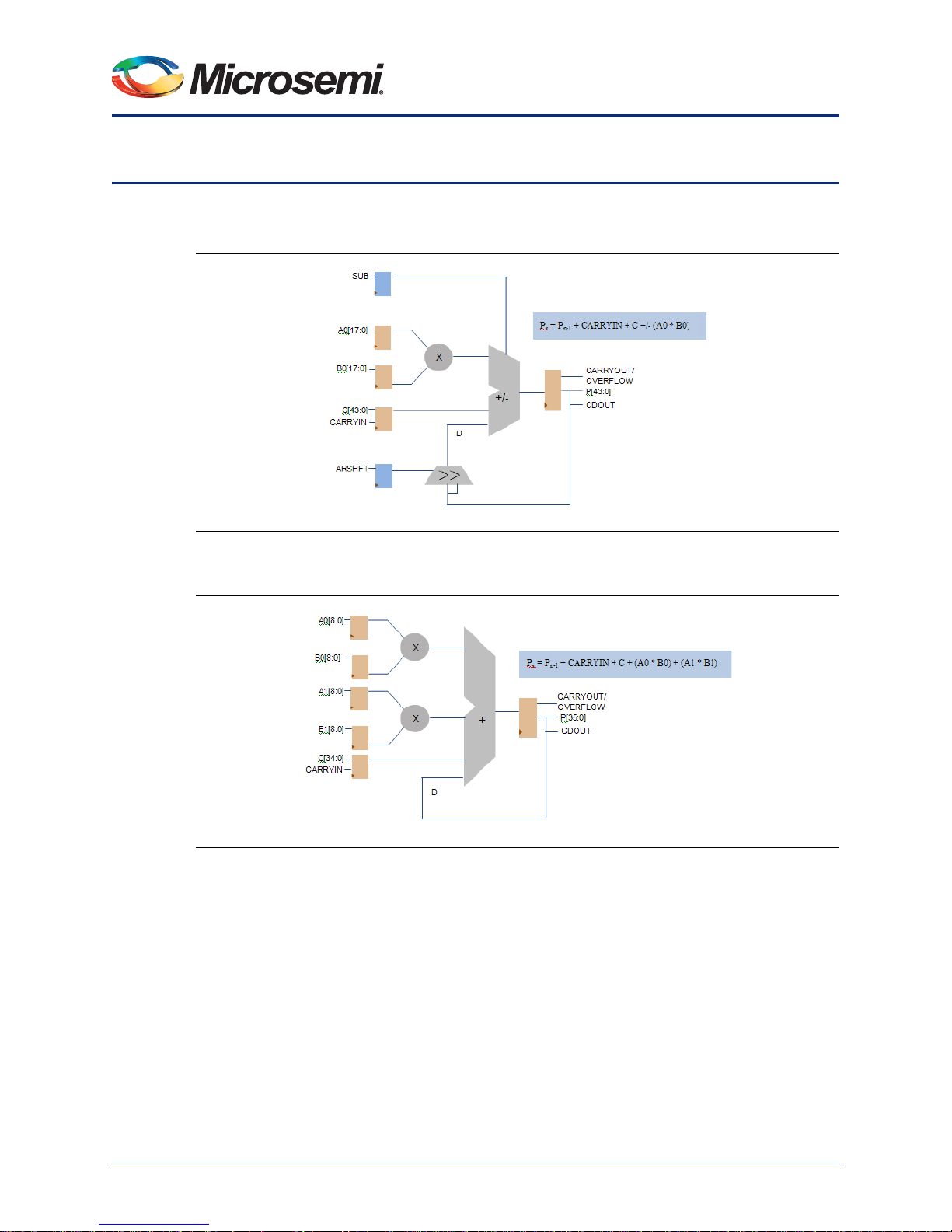
The Hard Multiplier Accumulator for SmartFusion2, IGLOO2, and RTG4 supports normal (Figure 1) and
dot product (Figure 2) multiplication. Blue registers indicate control signals; brown registers are for data.
Figure 1 • Normal Multiplier Accumulator
Figure 2 • Dot Product Multiplier Accumulator
Key Features
The Hard Multiplier Accumulator supports two operating modes: Normal and Dot Product.
• A structural netlist is generated in either Verilog or VHDL
• Individual inputs and outputs can be optionally registered with:
– A common rising edge clock
– Independent active-low asynchronous and synchronous clear controls
– Independent active-high enable controls
• An additional cascade output CDOUT can be enabled. This is the sign-extended 44 bit copy of
output P
• An additional Carry In input can be enabled
3
Page 4

• An additional Carry Out or Overflow output can be enabled.
• Normal Mode Features:
– Configurable operand widths for A0 and B0 between 2 and 18
– Configurable operand width for C between 2 and 44
– Optional as signment of operand A0 to an 18 bit two's complement constant
– Optional assignment of operand C to a 44 bit two’s complement constant
– Option to select between Multiplier followed by Adder, Subtractor or dynamic AddSub
– Optional Arithmetic Right Shift by 17 bits of the feedback input
• Dot Product Mode Features:
– Configurable operand widths for A0, B0, A1, B1 between 2 and 9.
– Configurable operand width for C between 2 and 35.
– Optional assignment of operand A0 and A1 to a 9 bit two's complement constant
– Optional assignment of Operand C to a 35 bit two’s complement constant
4
Page 5
1 – SmartDesign
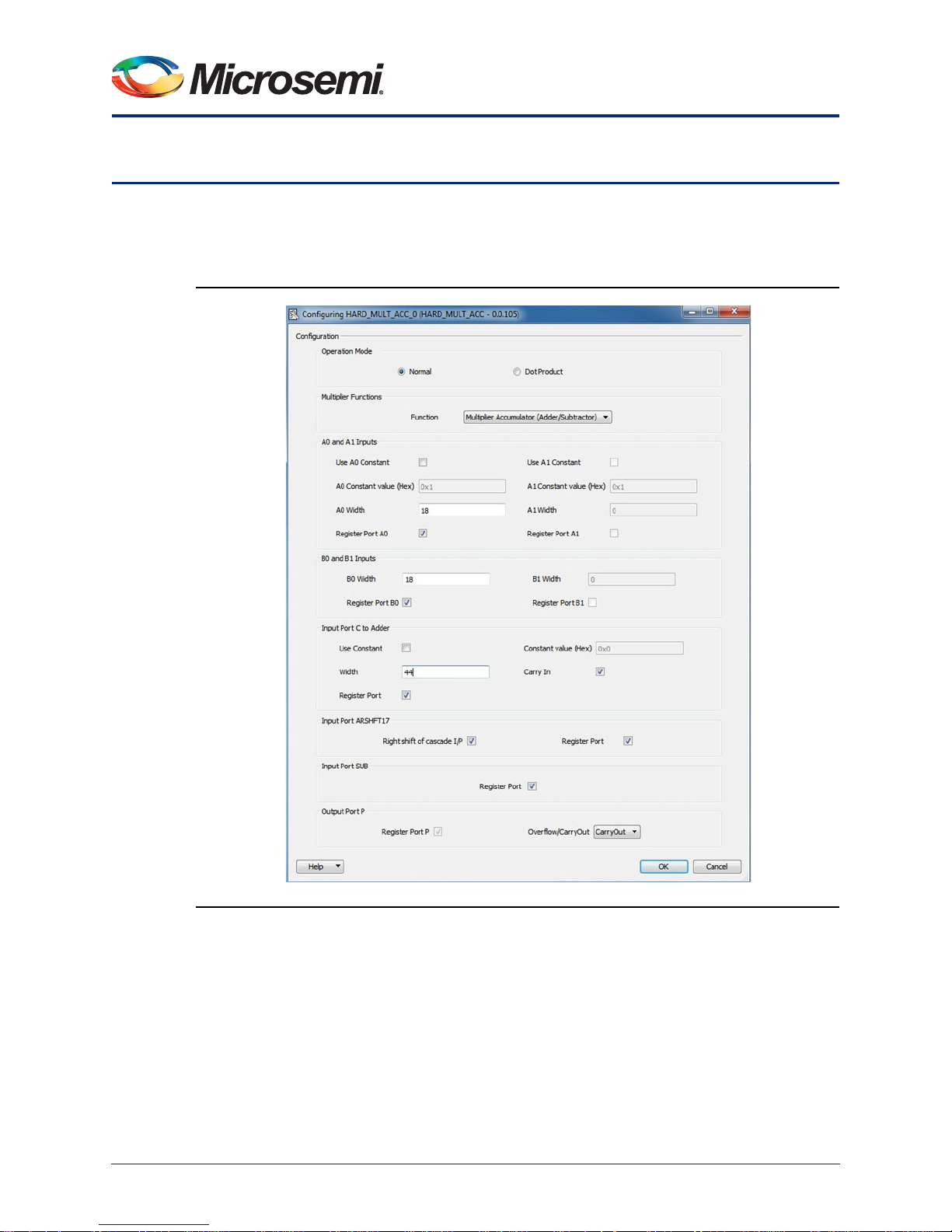
The Hard Multiplier Accumulator for SmartFusion2, IGLOO2, and RTG4 is available for download from
the Libero® SoC IP Catalog via the web repository. Once listed in the Catalog you can double-click the
macro to configure it in SmartDesign. For information on using SmartDesign to configure, connect, and
generate cores, see the Libero SoC online help.
Figure 1-1 • Hard Multiplier Accumulator Configuration Options - Normal Mode
5
Page 6

Figure 1-2 • Hard Multiplier Accumulator Configuration Options - Dot Product Mode
After configuring and generating the macro instance, you can simulate basic functionality. The macro can
then be instantiated as a component of a larger design.
6
Page 7

2 – Core Parameters
Table 2-1 lists the Normal mode Hard Multiplier Accumulator settings; Table 2-2 lists the Dot Product
mode settings.
Table 2-1 • Hard Multiplier Accumulator Normal Mode Configuration Description
Name Valid Range Description
Multiplier Functions
Function Multiplier
Accumulator
(Adder)
Multiplier
Accumulator
(Subtractor)
Multiplier
Accumulator
(Adder/Subtractor)
Input Port A0
Use Constant Sets input port A0 to constant
17
Constant Value (Hex) -2
Width 2 to 18 Width of input port A0; if shorter than 18 bits it is sign-extended. For
Register Port Registers input port A0 (if A0 is not set to constant)
Input Port B0
Width 2 to 18 Width of input port B0; if shorter than 18 bits it is sign-extended. For
to (217 - 1) Two's complement value of A0, if A0 is constant. Values shorter than
The Multiplier Accumulator with Adder/Subtractor exposes the SUB
control signal, which enables you to dynamically toggle between an
add or subtract operation.
18 bits are padded with zeros. Negative values must be a full 18 bits
wide. For example, 0x1FFFF means +131071 (2
means -1
example, if the width is 8, a value of 0x7F means +127 and a value of
0xFF means -1
example, if the width is 8, a value of 0x7F means +127 and a value of
0xFF means -1.
17
- 1), while 0x3FFFF
Register Port Registers input port B0
Input Port C
Use Constant Sets input port C to constant
43
Constant Value (Hex) -2
Width 2 to 44 Width of input port C; if shorter than 44 bits it is sign-extended. For
Carry In Carry in for C (if C is not set to constant)
to (243 - 1) Two's complement value of C, if C is constant. Values shorter than 44
bits are padded with zeros. Negative values must be a full 44 bits wide.
example, If the width is 8, a value of 0x7F means +127 and a value of
0xFF means -1.
7
Page 8

Table 2-1 • Hard Multiplier Accumulator Normal Mode Configuration Description (continued)
Name Valid Range Description
Register Port Registers input port C and Carry In (if C is not set to constant)
Input Port ARSHFT17
Right Shift of
Feedback input is arithmetic right-shifted by 17 if selected
Feedback Input
Register Port Registers ARSHFT17 control signal
Input Port SUB
Register Port Registers control input port SUB when Multiplier Accumulator with
Adder/Subtractor option is selected
Output Port P
Register Port Always Selected Registers output port P, CDOUT and Overflow/CarryOut
Overflow/CarryOut None, Overflow,
Select the output port function to include in the module interface
CarryOut
Table 2-2 • Hard Multiplier Accumulator Dot Product Mode Configuration Description
Name Valid Range Description
Input Port A0
Use Constant Sets input port A0 to constant
Constant Value (Hex) -28 to (28 - 1) Two's complement value of A0, if A0 is constant. Values shorter than 9
bits are padded with zeros. Negative values must be a full 9 bits wide.
For example, 0xFF means +255 (2
8
- 1), while 0x1FF means -1
Width 2 to 9 Width of input port A0; if shorter than 9 bits it is sign-extended. For
example, if the width is 8, a value of 0x7F means +127 and a value of
0xFF means -1.
Register Port Registers input port A0 (if A0 is not set to constant)
Input Port A1
Use Constant Sets input port A1 to constant
8
Constant Value (Hex) -2
to (28 - 1) Two's complement value of A1, if A1 is constant. Values shorter than 9
bits are padded with zeros. Negative values must be a full 9 bits wide.
For example, 0xFF means +255 (2
8
- 1), while 0x1FF means -1
Width 2 to 9 Width of input port A1; if shorter than 9 bits it is sign-extended. For
example, if the width is 8, a value of 0x7F means +127 and a value of
0xFF means -1.
Register Port Registers input port A1 (if A1 is not set to constant)
Input Port B0
8
Page 9

Table 2-2 • Hard Multiplier Accumulator Dot Product Mode Configuration Description
Name Valid Range Description
Width 2 to 9 Width of input port B0; if shorter than 9 bits it is sign-extended. For
example, if the width is 8, a value of 0x7F means +127 and a value of
0xFF means -1.
Register Port Registers input port B0
Input Port B1
Width 2 to 9 Width of input port B1; if shorter than 9 bits it is sign-extended. For
example, if the width is 8, a value of 0x7F means +127 and a value of
0xFF means -1.
Register Port Registers input port B1
Input Port C
Use Constant Sets input port C to constant
35
Constant Value (Hex) -2
to (235 - 1) Two's complement value of C, if C is constant. Values shorter than 35
bits are padded with zeros. Negative values must be a full 35 bits wide.
Width 2 to 35 Width of input port C; if shorter than 35 bits it is sign-extended. For
example, if the width is 8, a value of 0x7F means +127 and a value of
0xFF means -1.
Carry In Carry in for C (if C is not set to constant)
Register Port Registers input port C and Carry In (if C is not set to constant)
Output Port P
Register Port Always selected Registers output port P, CDOUT, and Overflow/CarryOut
Overflow/CarryOut None, Overflow,
Select the output port function to include in the module interface
CarryOut
9
Page 10

3 – Port Description
The figures below display the Hard Multiplier Accumulator input and output ports for Normal mode
(Figure 3-1) and Dot Product mode (Figure 3-2). Only a subset of the ports is used in any given Hard
Multiplier Accumulator configuration.
Figure 3-1 • Hard Multiplier Accumulator Ports, Normal Mode
Figure 3-2 • Hard Multiplier Accumulator Ports, Dot Product Mode
10
Page 11

Table 3-1 lists the Hard Multiplier Accumulator port signals fo r Normal mode.
Table 3-1 • Hard Multiplier Accumulator Ports - Normal Mode
Signal Direction Description
A0 Input Input data A0, 2- 18 bits wide
B0 Input Input data B0, 2- 18 bits wide
C Input Input data C, 2- 44 bits wide
CLK Input Input clock for all registers
A0_ACLR_N Input Asynchronous reset for data A0 registers
A0_SCLR_N Input Synchronous reset for data A0 registers
A0_EN Input Enable for data A0 registers
B0_ACLR_N Input Asynchronous reset for data B0 registers
B0_SCLR_N Input Synchronous reset for data B0 registers
B0_EN Input Enable for data B0 registers
C_ACLR_N Input Asynchronous reset for data C, Carry In registers
C_SCLR_N Input Synchronous reset for data C, Carry In registers
C_EN Input Enable for data C, Carry In registers
CARRYIN Input Carry In input for operand C
ARSHFT17_ACLR_N Input Asynchronous reset for ARSHF T17 register
ARSHFT17_SCLR_N Input Synchronous reset for ARSHF T17 register
ARSHFT17_EN Input Enable for ARSHFT17 register
SUB_ACLR_N Input Asynchronous reset for input control SUB registers
SUB_SCLR_N Input Synchronous reset for input control SUB registers
SUB_EN Input Enable for input control SUB registers
SUB Input Input control signal to select between add or subtract operation
P_ACLR_N Input Asynchronous reset for result P, CDOUT, Overflow/Carryout registers
P_SCLR_N Input Synchronous reset for result P, CDOUT, Overflow/Carryout registers
P_EN Input Enable for result P, CDOUT, Overflow/Carryout registers
P Output Pn = Pn-1 + CARRYIN + C + (A0 * B0) when SUB = 0
Pn = Pn-1 + CARRYIN + C - (A0 * B0) when SUB = 1
OVERFLOW Output When high, indicates that the result exceeded the width of output P.
OVERFLOW = (P[45] ^ P[44]) | (P[44] ^ P[43])
11
Page 12

Table 3-1 • Hard Multiplier Accumulator Ports - Normal Mode (continued)
Signal Direction Description
CARRYOUT Output This bit can be used to extend the adder in the fabric.
CARRYOUT = C[43] ^ D[43] ^ P[44]
CDOUT Output
Cascade
Cascade output of result P. CDOUT is a copy of P, sign-extended to 44
bits. The entire bus must either be dangling or drive an entire CDIN of
another MATH block in Normal mode.
Table 3-2 lists the Hard Multiplier Accumulator port signals fo r Dot Product mode.
Table 3-2 • Hard Multiplier Accumulator Ports - Dot Product Mode
Signal Direction Description
A0 Input Input data A0, 2- 9 bits wide
B0 Input Input data B0, 2- 9 bits wide
A1 Input Input data A1, 2- 9 bits wide
B1 Input Input data B1, 2- 9 bits wide
C Input Input data C, 2- 35 bits wide
CLK Input Input clock for all registers
A0_ACLR_N Input Asynchronous reset for data A0 registers
A0_SCLR_N Input Synchronous reset for data A0 registers
A0_EN Input Enable for data A0 registers
B0_ACLR_N Input Asynchronous reset for data B0 registers
B0_SCLR_N Input Synchronous reset for data B0 registers
B0_EN Input Enable for data B0 registers
A1_ACLR_N Input Asynchronous reset for data A1 registers
A1_SCLR_N Input Synchronous reset for data A1 registers
A1_EN Input Enable for data A1 registers
B1_ACLR_N Input Asynchronous reset for data B1 registers
B1_SCLR_N Input Synchronous reset for data B1 registers
B1_EN Input Enable for data B1 registers
C_ACLR_N Input Asynchronous reset for data C, Carry In registers
C_SCLR_N Input Synchronous reset for data C, Carry In registers
C_EN Input Enable for data C, Carry In registers
CARRYIN Input Carry In input for operand C
P_ACLR_N Input Asynchronous reset for result P, CDOUT, Overflow/Carryout registers
12
Page 13

Table 3-2 • Hard Multiplier Accumulator Ports - Dot Product Mode (continued)
Signal Direction Description
P_SCLR_N Input Synchronous reset for result P, CDOUT, Overflow/Carryo ut registe r s
P_EN Input Enable for result P, CDOUT, Overflow/Carryout registers
P Output Pn = Pn-1 + CARRYIN + C + (A0 * B0) + (A1*B1)
OVERFLOW Output When high, indicates that the result exceeded the width of output P.
OVERFLOW = (P[36] ^ P[35]) | (P[35] ^ P[34])
CARRYOUT Output This bit can be used to extend the adder in the fabric.
CARRYOUT = C[34] ^ D[34] ^ P[35]
CDOUT Output
Cascade
Cascade output of result P. CDOUT is a sign-extended copy of P. The entire bus
must either be dangling or drive an entire CDIN of another MATH block in Dot
Product mode.
13
Page 14

A – Product Support
Microsemi SoC Products Group backs its products with various support services, including Customer
Service, Customer Technical Support Center, a website, electronic mail, and worldwide sales offices.
This appendix contains information about contacting Mi crosemi SoC Products Group and using these
support services.
Customer Service
Contact Customer Service for non-technical product support, such as product pricing, product upgrades,
update information, order status, and authorization.
From North America, call 800.262.1060
From the rest of the world, call 650.318.4460
Fax, from anywhere in the world, 408.643.6913
Customer Technical Support Center
Microsemi SoC Products Group staffs its Customer Technical Support Center with highly skilled
engineers who can help answer your hardware, software, and design questions about Microsemi SoC
Products. The Customer Technical Support Center spends a great deal of time creating application
notes, answers to common design cycle questions, documentation of known issues, and various FAQs.
So, before you contact us, please visit our online resources. It is very likely we have already answered
your questions.
Technical Support
Visit the Customer Support website (www.microsemi.com/soc/support/search/default.aspx) for more
information and support. Many answers available on the searchable web resource include diagrams,
illustrations, and links to other resources on the website.
Website
You can browse a variety of technical and non-technical information on the SoC home page, at
www.microsemi.com/soc.
Contacting the Customer Technical Support Center
Highly skilled engineers staff the Technical Support Cen te r. The Technical Support Center can be
contacted by email or through the Microsemi SoC Products Group website.
Email
Y ou can communicate your technical questions to our email address and receive answers back by email,
fax, or phone. Also, if you have design problems, you can email your design files to receive assistance.
We constantly monitor the email account throughout the day. When sending your request to us, please
be sure to include your full name, company name, and your contact information for efficient processing of
your request.
The technical support email address is soc_tech@microsemi.com.
14
Page 15

My Cases
Microsemi SoC Products Group customers may submit and track technical cases online by going to My
Cases.
Outside the U.S.
Customers needing assistance outside the US time zones can either contact technical support via email
(soc_tech@microsemi.com) or contact a local sales office. Sales office listings can be found at
www.microsemi.com/soc/company/contact/default.aspx.
ITAR Technical Support
For technical support on RH and RT FPGAs that are regulated by International Traffic in Arms Regulations
(ITAR), contact us via soc_tech_itar@microsemi.com. Alternatively, within My Cases, select Yes in the ITAR
drop-down list. For a complete list of ITAR-regulated Microsemi FPGAs, visit the ITAR web page.
Microsemi Corporation (Nasdaq: MSCC) offers a comprehensive portfolio of semiconductor
and system solutions for communications, defense and security, aerospace, and industrial
markets. Products include high-performance and radiation-hardened analog mixed-signal
integrated circuits, FPGAs, SoCs, and ASICs; power management products; timing and
synchronization devices and precise time solutions, setting the world's standard for time; voice
processing devices; RF solutions; discrete components; security technologies and scalable
anti-tamper products; Power-over-Ethernet ICs and midspans; as well as custom design
Microsemi Corporat e Headquarters
One Enterprise, Aliso Viejo,
CA 92656 USA
Within the USA: +1 (800) 713-4113
Outside the USA: +1 (949) 380-6100
Sales: +1 (949) 380-6136
Fax: +1 (949) 215-4996
E-mail: sales.support@microsemi.com
©2015 Microsemi Corporation. All rights
reserved. Microsemi and the Microsemi
logo are trademarks of Microsemi
Corporation. All other trademarks and
service marks are the property of their
respective owners.
capabilities and services. Microsemi is headquartered in Aliso Viejo, Calif. and has
approximately 3,400 employees globally. Learn more at www.microsemi.com.
Microsemi makes no warranty, representation, or guarantee regarding the information contained herein or
the suitability of its products and services for any particular purpose, nor does Microsemi assume any
liability whatsoever arising out of the application or use of any product or circuit. The products sold
hereunder and any other products sold by Microsemi have been subject to limited testing and should not
be used in conjunction with mission-critical equipment or applications. Any performance specifications are
believed to be reliable but are not verified, and Buyer must conduct and complete all performance and
other testing of the products, alone and together with, or installed in, any end-products. Buyer shall not rely
on any data and performance specifications or parameters provided by Microsemi. It is the Buyer's
responsibility to independently determine suitability of any products and to test and verify the same. T he
information provided by Microsemi hereunder is provided "as is, where is" and with all faults, and the entire
risk associated with such information is entirely with the Buyer. Microsemi does not grant, explicitly or
implicitly, to any party any patent rights, licenses, or any other IP rights, whether with regard to such
information itself or anything described by such information. Information provided in this document is
proprietary to Microsemi, and Microsemi reserves the right to make any changes to the information in this
document or to any products and services at any time without notice.
5-02-00369-1/04.15
 Loading...