

Microsemi RAID 3101-4i, RAID 3151-4i, RAID 3102-8i, RAID 3152-8i, RAID 3154-8i Service Manual
...Page 1

Installation and User's Guide
Microsemi Adaptec®SmartRAID 3100 Series and
SmartHBA 2100 Series Host Bus Adapters
Released
September 2017
.
Page 2

Revision History
1
2017
Details of ChangeIssue DateIssue
First Production Release.September
2CONFIDENTIAL Installation and User's Guide Issue 1
Page 3

Contents
Microsemi Adaptec®Product Support.............................................................................................8
Limited 3-Year Hardware Warranty.................................................................................................9
Regulatory Compliance Statements...............................................................................................10
1 About This Guide........................................................................................................................13
1.1 What You Need to Know Before You Begin.................................................................................................13
1.2 Terminology Used in this Guide..................................................................................................................13
1.3 How to Find More Information...................................................................................................................13
2 Kit Contents and System Requirements.....................................................................................15
2.1 Kit Contents................................................................................................................................................15
2.2 System Requirements ................................................................................................................................15
3 About Your SmartRAID 3100 Series Host Bus Adapter ..............................................................16
3.1 Standard Features.......................................................................................................................................16
3.2 Mechanical Information .............................................................................................................................16
3.2.1 Board Dimensions.........................................................................................................................16
3.2.2 Heat Sink.......................................................................................................................................16
3.3 Visual Indicators..........................................................................................................................................17
3.4 About the Microsemi Adaptec SmartRAID 3101-4i/3151-4i.......................................................................19
3.5 About the Microsemi Adaptec SmartRAID 3102-8i/3152-8i/3154-8i.........................................................20
3.6 About the Microsemi Adaptec SmartRAID 3154-8e...................................................................................21
3.7 About the Microsemi Adaptec SmartRAID 3154-16i..................................................................................22
3.8 About the Microsemi Adaptec SmartRAID 3154-24i..................................................................................23
4 About Your SmartHBA 2100 Series Host Bus Adapter ...............................................................24
4.1 Standard Features.......................................................................................................................................24
4.2 Mechanical Information .............................................................................................................................24
4.2.1 Board Dimensions.........................................................................................................................24
4.2.2 Heat Sink.......................................................................................................................................24
4.3 Visual Indicators..........................................................................................................................................25
4.4 About the Microsemi Adaptec SmartHBA 2100-4i4e.................................................................................26
4.5 About the Microsemi Adaptec SmartHBA 2100-8i.....................................................................................27
4.6 About the Microsemi Adaptec SmartHBA 2100-24i...................................................................................28
5 Installing the Controller and Disk Drives....................................................................................29
5.1 Before You Begin.........................................................................................................................................29
5.2 Selecting Disk Drives and Cables ................................................................................................................29
5.2.1 Disk Drives....................................................................................................................................29
5.2.2 Cables...........................................................................................................................................29
5.3 Installing the Host Bus Adapter..................................................................................................................30
6 Installing the Driver and an Operating System ..........................................................................33
6.1 Download the Driver Package.....................................................................................................................33
6.2 Creating a Driver Disk.................................................................................................................................33
6.3 Installing with Windows .............................................................................................................................33
3CONFIDENTIAL Installation and User's Guide Issue 1
Page 4

6.4 Installing with Red Hat Linux or CentOS.....................................................................................................34
6.5 Installing with SuSE Linux Enterprise Server...............................................................................................35
6.6 Installing with Oracle Linux.........................................................................................................................36
6.7 Installing with Ubuntu Linux.......................................................................................................................37
6.8 Installing with Debian Linux........................................................................................................................38
6.9 Installing with FreeBSD...............................................................................................................................39
6.10 Installing with Solaris................................................................................................................................41
6.10.1 Installing with Solaris Live Media...............................................................................................41
6.10.2 Installing with Solaris Text Installer.............................................................................................42
6.11 Installing with Citrix XenServer ................................................................................................................43
6.12 Installing with VMware ............................................................................................................................43
7 Installing the Driver on an Existing Operating System ..............................................................45
7.1 Download the Driver Package.....................................................................................................................45
7.2 Creating a Driver Disk.................................................................................................................................45
7.3 Installing on Windows ................................................................................................................................45
7.4 Installing on Red Hat or CentOS..................................................................................................................46
7.5 Installing on SuSE Linux Enterprise Server..................................................................................................47
7.6 Installing on Oracle Linux............................................................................................................................48
7.7 Installing on Ubuntu Linux..........................................................................................................................49
7.8 Installing on Debian Linux...........................................................................................................................50
7.9 Installing on FreeBSD..................................................................................................................................50
7.10 Installing on Solaris...................................................................................................................................50
7.11 Installing on Citrix XenServer....................................................................................................................52
7.12 Installing on VMware................................................................................................................................52
8 Solving Problems .......................................................................................................................53
8.1 Troubleshooting Checklist...........................................................................................................................53
8.2 Resetting the Adapter ................................................................................................................................53
Appendix A Using the Microsemi SAS/SATA Conguration Utility................................................54
A.1 Running the Microsemi SAS/SATA Conguration Utility: Ctrl-A or UEFI/HII? ............................................54
A.2 Controller Information................................................................................................................................55
A.3 Creating an Array........................................................................................................................................55
A.4 Managing Arrays and Logical Drives...........................................................................................................55
A.4.1 Viewing Logical Drive Properties..................................................................................................55
A.4.2 Creating Logical Drives.................................................................................................................56
A.4.3 Enabling IO Bypass.......................................................................................................................56
A.4.4 Editing Logical Drive Properties....................................................................................................56
A.4.5 Deleting a Logical Drive................................................................................................................57
A.4.6 Assigning Spares...........................................................................................................................57
A.4.7 Deleting a Spare Drive..................................................................................................................57
A.4.8 Identifying the Drives in an Array.................................................................................................58
A.4.9 Deleting an Array..........................................................................................................................58
A.5 Modifying SmartHBA 2100/SmartRAID 3100 controller Settings ..............................................................58
A.6 Clearing the Controller Conguration........................................................................................................60
A.7 Backup Power Source.................................................................................................................................60
A.8 Manage Power Settings..............................................................................................................................60
A.9 BMC Settings..............................................................................................................................................61
A.10 Device Information...................................................................................................................................61
A.11 Identifying a Disk Drive.............................................................................................................................61
A.12 Erasing a Disk Drive..................................................................................................................................62
A.13 Updating Drive Firmware.........................................................................................................................62
A.14 Clearing RAID Meta-data..........................................................................................................................63
4CONFIDENTIAL Installation and User's Guide Issue 1
Page 5

A.15 Setting the Bootable Device(s) for Legacy Boot Mode.............................................................................63
A.16 Updating the SmartHBA 2100/SmartRAID 3100 controller Firmware......................................................63
A.17 Creating a Support Archive.......................................................................................................................64
Appendix B Installing the SmartPQI Drivers from Source ............................................................65
B.1 Installation Instructions for Supported Linux OS's......................................................................................65
B.2 Using the Installation DVD as the Repository.............................................................................................67
Appendix C Safety Information.....................................................................................................69
C.1 Electrostatic Discharge (ESD)......................................................................................................................69
Appendix D Technical Specications.............................................................................................70
D.1 Environmental Specications.....................................................................................................................70
D.2 DC Power Requirements.............................................................................................................................70
D.3 Current and Power Requirements .............................................................................................................70
5CONFIDENTIAL Installation and User's Guide Issue 1
Page 6

Figures
Figure 1 • SmartRAID 3100 Series LED Locations.........................................................................................................17
Figure 2 • Microsemi Adaptec SmartRAID 31x1-4i.......................................................................................................19
Figure 3 • Microsemi Adaptec SmartRAID 31xx-8i.......................................................................................................20
Figure 4 • Microsemi Adaptec SmartRAID 3154-8e......................................................................................................21
Figure 5 • Microsemi Adaptec SmartRAID 3154-16i.....................................................................................................22
Figure 6 • Microsemi Adaptec SmartRAID 3154-24i.....................................................................................................23
Figure 7 • SmartHBA 2100 Series Status LEDs..............................................................................................................25
Figure 8 • Microsemi Adaptec SmartHBA 2100-4i4e....................................................................................................26
Figure 9 • Microsemi Adaptec SmartHBA 2100-8i Features.........................................................................................27
Figure 10 • Microsemi Adaptec SmartHBA 2100-24i Features.....................................................................................28
6CONFIDENTIAL Installation and User's Guide Issue 1
Page 7

Tables
Table 1 • SmartRAID 3100 Series Board Dimensions ..............................................................................................16
Table 2 • SmartRAID 3100 Series Status LEDs .........................................................................................................17
Table 3 • SmartRAID 3100 Series DDR/FBWC LED States ........................................................................................18
Table 4 • SmartHBA 2100 Series Board Dimensions ...............................................................................................24
Table 5 • SmartHBA 2100 Series Status LEDs ..........................................................................................................25
7CONFIDENTIAL Installation and User's Guide Issue 1
Page 8

Microsemi Adaptec®Product Support
If you have questions about installing or using your Microsemi Adaptec®product, check this document
rst—you will nd answers to most of your questions. If you need further assistance, use the support
options listed below. To expedite your service, have your computer in front of you.
Note: Please visit our Support site at start.microsemi.com for the most up to date contact
information.
Self Help and Support in English
• Search the Microsemi Support Knowledgebase (ASK) at ask.microsemi.com for articles,
troubleshooting tips, and frequently asked questions for your product.
• For support through email, submit your question at ask.microsemi.com.
• To contact Technical Support, visit our product support site at start.microsemi.com.
Technische Informationen und Support in Deutsch
• Suchen Siein der Adaptec Support Knowledgebase (ASK) unter ask-de.microsemi.com nach Artikeln,
Tipps zur Fehlerbehebung und häug gestellten Fragen zu Ihrem Produkt.
• Support per Email erhalten Sie unter ask-de.microsemi.com.
• Um den Technischen Support zu kontaktieren, besuchen Sie uns bitte unter start.microsemi.com
und klicken Sie auf „Support kontaktieren“, für Auswahlmöglichkeiten.
Техническая поддержка и информация на русском языке
• База знанийMicrosemi (ASK) на сайте ask-ru.microsemi.comask-ru.adaptec.com – статьи, советы
по устранению неисправностей и часто задаваемые вопросы о Вашем продукте.
• Для поддержки по электронной почте отправьте Ваш запрос на сайте ask-ru.microsemi.com
• Для обращения в службу Технической Поддержки, пожалуйста, посетите наш web сайт
start.microsemi.com и используйте ссылку "Contact Support".
日本語での技術情報とサポート
• ask.microsemi.co.jp のMicrosemi Support Knowledgebase (ASK)で、お使いの製品の情報 トラブル
シューティングのヒント、よくある質問を検索してください。
• Eメールでのサポートには ask.microsemi.co.jp から質問を送ってください。
• テクニカルサポートへコンタクトするには、弊社ウェブサイトstart.microsemi.comをご覧になり、"Contact
Support“をクリックして下さい。
8CONFIDENTIAL Installation and User's Guide Issue 1
Page 9

Limited 3-Year Hardware Warranty
1. Microsemi Corporation (“Microsemi”) warrants to the purchaser of this product that it will be free
from defects in material and workmanship for a period of three (3) years from the date of purchase.
If the product should become defective within the warranty period, Microsemi, at its option, will
repair or replace the product, or refund the purchaser's purchase price for the product, provided it
is delivered at the purchaser's expense to an authorized Microsemi service facility or to Microsemi.
2. Repair or replacement parts or products will be furnished on an exchange basis and will either be
new or reconditioned and will be subject to original warranty term. All replaced parts or products
shall become the property of Microsemi. This warranty shall not apply if the product has been
damaged by accident, misuse, abuse or as a result of unauthorized service or parts.
3. Warranty service is available to the purchaser by delivering the product during the warranty period
to an authorized Microsemi service facility or to Microsemi and providing proof of purchase price
and date. The purchaser shall bear all shipping, packing, and insurance costs and all other costs,
excluding labor and parts, necessary to effectuate repair, replacement or refund under thiswarranty.
4. For more information on how to obtain warranty service, click on the Services & Support link at
microsemi.com.
5. THIS LIMITED WARRANTY DOES NOT EXTEND TO ANY PRODUCT WHICH HAS BEEN DAMAGED AS A
RESULT OF ACCIDENT, MISUSE, ABUSE, OR AS A RESULT OF UNAUTHORIZED SERVICE OR PARTS.
6. THIS WARRANTY IS IN LIEU OF ALLOTHER EXPRESS WARRANTIES WHICH NOW ORHEREAFTER MIGHT
OTHERWISE ARISE RESPECT TO THIS PRODUCT. IMPLIED WARRANTIES, INCLUDING THOSE OF
MERCHANTABILITY, FITNESS FOR A PARTICULAR PURPOSE AND NON-INFRINGEMENT SHALL (A)
HAVE NO GREATER DURATION THAN 3 YEARS FROM THE DATE OF PURCHASE, (B) TERMINATE
AUTOMATICALLY AT THE EXPIRATION OF SUCH PERIOD AND (C) TO THE EXTENT PERMITTED BY LAW
BE EXCLUDED. IN THE EVENT THIS PRODUCT BECOMES DEFECTIVE DURING THE WARRANTY PERIOD,
THE PURCHASER'S EXCLUSIVE REMEDY SHALL BE REPAIR, REPLACEMENT OR REFUND AS PROVIDED
ABOVE. INCIDENTAL OR CONSEQUENTIAL DAMAGES, INCLUDING WITHOUT LIMITATION LOSS OF
DATA, ARISING FROMBREACH OF ANY EXPRESS ORIMPLIED WARRANTY ARE NOTTHE RESPONSIBILITY
OF MICROSEMI AND, TO THE EXTENT PERMITTED BY LAW, ARE HEREBY EXCLUDED BOTH FOR
PROPERTY DAMAGE, ANDTO THE EXTENTNOT UNCONSCIONABLE, FORPERSONAL INJURY DAMAGE.
7. WITHIN THE US, SOME STATES DO NOT ALLOW THE EXCLUSION OR LIMITATION OF INCIDENTAL OR
CONSEQUENTIAL DAMAGES FOR CONSUMER PRODUCTS, AND SOME STATES DO NOT ALLOW
LIMITATIONS ON HOW LONG AN IMPLIED WARRANTY LASTS, SO THE ABOVE LIMITATION OR
EXCLUSIONS MAY NOT APPLY TO YOU.
8. THIS WARRANTY GIVES YOU SPECIFIC LEGAL RIGHTS, AND YOU MAY ALSO HAVE OTHER RIGHTS
WHICH VARY DEPENDING ON WHERE YOU RESIDE.
9. FOR AUSTRALIA RESIDENTS, IF THE PRODUCT SHOULD BECOME DEFECTIVE WITHIN THE WARRANTY
PERIOD, MICROSEMI, AT ITS OPTION, WILL REPAIR OR REPLACE THE PRODUCT, OR REFUND THE
PURCHASER'S PURCHASE FOR THE PRODUCT, PROVIDED IT IS DELIVERED AT THE PURCHASER'S
EXPENSE BACK TO THE PLACE OF PURCHASE AFTER MICROSEMI TECHNICAL SUPPORT HAS ISSUED
AN INCIDENT NUMBER. IN ADDITION TO THE WARRANTIES SET FORTH HEREIN, OUR GOODS COME
WITH GUARANTEES THAT CANNOT BE EXCLUDED UNDER THE AUSTRALIAN CONSUMER LAW. YOU
ARE ENTITLED TO A REPLACEMENT OR REFUND FOR A MAJOR FAILURE AND FOR COMPENSATION
FOR ANY OTHER REASONABLY FORESEEABLE LOSS OR DAMAGE. YOU ARE ALSO ENTITLED TO HAVE
THE GOODS REPAIRED OR REPLACED IF THE GOODS FAIL TO BE OF ACCEPTABLE QUALITY AND THE
FAILURE DOES NOT AMOUNT TO A MAJOR FAILURE.
9CONFIDENTIAL Installation and User's Guide Issue 1
Page 10

Regulatory Compliance Statements
Federal Communications Commission Radio Frequency Interference Statement
Attention: Changes or modications to this unit not expressly approved by the party responsible
for compliance could void the user's authority to operate the equipment.
This equipment has been tested and found to comply with thelimits for a Class B digital device, pursuant
to Part 15 of the FCC rules. These limits are designed to provide reasonable protection against harmful
interferencein a residential installation. This equipment generates, uses, and can radiate radio frequency
energy, and if not installed and used in accordance with the instruction manual, may cause harmful
interference to radio communications. However, there is no guarantee that interference will not occur
in a particular installation. However, if this equipment does cause interference to radio or television
equipment reception, which can be determined by turning the equipment off and on, the user is
encouraged to try to correct the interference by one or more of the following measures:
• Reorient or relocate the receiving antenna.
• Increase the separation between equipment and receiver.
• Connect the equipment to an outlet on a circuit different from that to which the receiver is
connected.
• Consult the dealer or an experienced radio/television technician for help.
• Use a shielded and properly grounded I/O cable and power cable to ensure compliance of this unit
to the specied limits of the rules.
This device complies with part 15 of the FCC rules. Operation is subject to the following two conditions:
(1) this device may not cause harmful interference and (2) this device must accept any interference
received, including interference that may cause undesired operation.
UL Compliance Statement
Microsemi Adaptec products are tested and listed by Underwriters Laboratories, Inc. to UL 60950-1
Second Edition and IEC-60950-1 Second Edition standards, le numbers E175975. Microsemi Adaptec
products are for use only with UL listed ITE.
Microsemi Adaptec SmartRAID 3101-4i/Microsemi Adaptec SmartRAID 3151-4i/
Microsemi Adaptec SmartRAID 3102-8i/Microsemi Adaptec SmartRAID 3152-8i/
Microsemi Adaptec SmartRAID 3154-8i/Microsemi Adaptec SmartRAID 3154-8e/
Microsemi Adaptec SmartRAID 3154-16i/Microsemi Adaptec SmartRAID 3154-24i
Microsemi Adaptec SmartHBA 2100-8i/Microsemi Adaptec SmartHBA 2100-24i/
Use only with the listed ITE:Microsemi Corporation
Microsemi Adaptec SmartHBA 2100-4i4e
10CONFIDENTIAL Installation and User's Guide Issue 1
Page 11
European Union Compliance Statement
This Information Technology Equipment has been tested and found to comply with EMC Directive 2014
/30/EU, in accordance with:
• EN55032 (2014) Emissions:
Class B ITE radiated and conducted emissions•
• EN55024 (2010) Immunity:
• EN61000-4-2 (2009) Electrostatic discharge: ±4 kV contact, ±8 kV air
• EN61000-4-3 (2010) Radiated immunity: 3V/m
• EN61000-4-4 (2012) Electrical fast transients/burst: ±1 kV AC, ±0.5 kV I/O
• EN61000-4-5 (2014) Surges: ±1 kV differential mode, ±2 kV common mode
• EN61000-4-6 (2014) Conducted immunity: 3 V
• EN61000-4-11 (2004) Supply dips and variations: 30% and 100%
• EN50581 (2012) Technical Documentation:
• For the assessment of electrical and electronic products with respect to the restriction of hazardous substances
In addition, all equipment requiring U.L. listing has been found to comply with EMC Directive 2014/35/
EU, in accordance with EN60950 with amendments A1, A2, A3, A4, A11, A12.
Australian/New Zealand Compliance Statement
This device has been tested and found to comply with the limits for a Class B digital device, pursuant to
the Australian/New Zealand standard AS/NZS 3548 set out by the Spectrum Management Agency.
Canadian Compliance Statement
This Class B digital apparatus meets all requirements of the Canadian Interference-Causing Equipment
Regulations.
Cet appareilnumérique de la classe B respecte toutes les exigencesdu Règlement sur le matériel brouilleur
du Canada.
Japanese Compliance (Voluntary Control Council Initiative)
This equipment complies to class B Information Technology equipment based on VCCI (Voluntary Control
Council for Interface). This equipment is designed for home use but it may causes radio frequency interference problem ifused toonear to a television or radio. Please handle it correctlyper thisdocumentation.
Korean Compliance (KCC) Statement
Microsemi Adaptec products are tested and certied by KCC:
Korean Compliance (KCC) Statement:
MSIP-REM-M2C-3154-8i
The above certication covers the following series:
Microsemi Adaptec SmartRAID 3101-4i
Microsemi Adaptec SmartRAID 3151-4i
Microsemi Adaptec SmartRAID 3102-8i
Microsemi Adaptec SmartRAID 3152-8i
Microsemi Adaptec SmartRAID 3154-8i
11CONFIDENTIAL Installation and User's Guide Issue 1
Page 12
Microsemi Adaptec SmartHBA 2100-8i
Korean Compliance (KCC) Statement:
MSIP-REM-M2C-3154-8e
The above certication covers the following series:
Microsemi Adaptec SmartRAID 3154-8e
Korean Compliance (KCC) Statement:
MSIP-REM-M2C-3154-24i
The above certication covers the following series:
Microsemi Adaptec SmartRAID 3154-16i w/ ASCM-35F
Microsemi Adaptec SmartRAID 3154-24i w/ ASCM-35F
Microsemi Adaptec SmartHBA 2100-24i
Korean Compliance (KCC) Statement:
MSIP-REM-M2C-2100-4i4e
The above certication covers the following series:
Microsemi Adaptec SmartHBA 2100-4i4e
This equipment is home use (Class B) electromagnetic wave suitability equipment and to be used mainly
at home and it can be used in all areas.
12CONFIDENTIAL Installation and User's Guide Issue 1
Page 13

About This Guide
1 About This Guide
This Installation and User's Guide explains howto install and setup your Microsemi Adaptec®SmartRAID
3100 or SmartHBA 2100 Series Host Bus Adapter, including driver installation, BIOS operations,
troubleshooting tips, and instructions for ashing the adapter rmware.
These SmartRAID 3100 Series adapter models are described in this guide:
• Microsemi Adaptec SmartRAID 3101-4i
• Microsemi Adaptec SmartRAID 3151-4i
• Microsemi Adaptec SmartRAID 3102-8i
• Microsemi Adaptec SmartRAID 3152-8i
• Microsemi Adaptec SmartRAID 3154-8i
• Microsemi Adaptec SmartRAID 3154-8e
• Microsemi Adaptec SmartRAID 3154-16i
• Microsemi Adaptec SmartRAID 3154-24i
These SmartHBA 2100 Series adapter models are described in this guide:
• Microsemi Adaptec SmartHBA 2100-8i
• Microsemi Adaptec SmartHBA 2100-4i4e
• Microsemi Adaptec SmartHBA 2100-24i
1.1 What You Need to Know Before You Begin
This guide is written for data storage and IT professionals who are responsible for installing, conguring,
and maintaining SmartRAID 3100 Series and SmartHBA 2100 Series Host Bus Adapters in computers or
servers in a "cloud" or data center environment. You should be familiar with computer hardware,
operating system administration, data storage devices, and SAS and Serial ATA (SATA) technology.
If you are responsible for conguring the storage resources on the SmartRAID and SmartHBA adapters,
you should be familiar with RAID technology and creating bootable volumes.
1.2 Terminology Used in this Guide
Many of the terms and concepts referred to in this guide are known to computer users by multiple
names. This guide uses these terms:
• Host Bus Adapter or HBA (also known as controller, adapter, or I/O card)
• Disk drive (also known as hard disk, hard drive, or hard disk drive)
• Solid State Drive (also known as SSD or non-rotating storage media)
• Enclosure (also known as a storage enclosure, disk drive enclosure, or JBOD)
1.3 How to Find More Information
You can nd more information about your SmartRAID 3100 Series or SmartHBA 2100 Series Host Bus
Adapter by referring to these documents.
• ARCCONF Command Line Utility User's Guide for Microsemi Smart Storage Controllers—Describes
how to use the ARCCONF utility to perform conguration and storage management tasks from an
interactive command line. (ESC-2161615)
• Microsemi Adaptec SmartRAID 3100 Series and SmartHBA 2100Series Host Bus Adapters Installation
and User's Guide (this manual)—Describes how to install SmartRAID 3100 and SmartHBA 2100
Series adapters in a computer or server, install drivers, and congure the adapter for initial use.
(ESC-2171547)
• Microsemi Adaptec Flash Backup Module ASCM-35 Installation Instructions—Describes how to
install the ASCM-35 Flash Backup module using the mounting plate method. (ESC-2170352)
13CONFIDENTIAL Installation and User's Guide Issue 1
Page 14

About This Guide
• Microsemi Adaptec SmartRAID 3100 and SmartHBA 2100 Software/Firmware Release
Notes—Includes updated product information, known issues, and limitations. (ESC-2161026)
14CONFIDENTIAL Installation and User's Guide Issue 1
Page 15

Kit Contents and System Requirements
2 Kit Contents and System Requirements
This section lists the contents of your SmartRAID 3100 Series or SmartHBA 2100 Series kit and the system
requirements for successfully installing and using your adapter.
2.1 Kit Contents
SmartRAID 3100 Series kits:
• SmartRAID 3100 Series adapter
• Full-height ("FH") and Low-prole ("LP") brackets, with mounting screws
• ASCM-35F Supercap Module, including:
Supercap module extension cable•
• Full-height and Low-prole mounting plate, with mounting screws
• Supercap mounting clip
• Tie-wraps (nylon)
SmartHBA 2100 Series kits:
• SmartHBA 2100 Series adapter
• Full-height ("FH") and Low-prole ("LP") brackets, with mounting screws
Note: The latest rmware, drivers, utilities software, and documentation can be downloaded at
storage.microsemi.com. For more information, see Downloading the Driver Package.
2.2 System Requirements
• PC-compatible computer with Intel Pentium, or equivalent, processor
• 4 GB of RAM minimum
• Available compatible PCIe slot (depending on your adapter model—see the descriptions in About
Your Host Bus Adapter)
• One of these operating systems:
• Microsoft®Windows®Server, Windows 10, Windows 8.1, Windows 7
• Red Hat®Enterprise Linux
• CentOS
• SuSE Linux Enterprise Server
• Ubuntu Linux
• Debian Linux
• Oracle Linux
• Citrix Xenserver
• Solaris
• FreeBSD
• VMware ESXi
See the Release Notes for a complete list of supported OSs and OS versions.
• USB ash drive or CD burner, for creating driver disks and bootable media
15CONFIDENTIAL Installation and User's Guide Issue 1
Page 16
About Your SmartRAID 3100 Series Host Bus Adapter
3 About Your SmartRAID 3100 Series Host Bus Adapter
This section provides an overview of the features of the SmartRAID 3100 Series adapter.
3.1 Standard Features
• Support for SAS and SATA Hard Disk Drives (HDD) and Solid State Drives (SSD)
• uEFI pre-boot BIOS, CTRL-A conguration utility
• Flash ROM for updates to rmware and BIOS
• Up to 24 ports, 12 Gb/s I/O
• SAS 3.0, PCIe 3.0
• Low-prole MD2 form factor
• Mini-SAS HD connectors
• Cache protection with supercapacitor module
• Support for disk drive enclosures with SES2 enclosure management hardware
• Thermal sensor, with logging capabilities
• GUI and CLI management utilities
• Support for RAID 0, 1, 5, 6, 10, 50, 60
• Universal asynchronous receiver/transmitter (UART) debug/diagnostic port
Note: See the Product Brief for a complete list of supported features.
3.2 Mechanical Information
3.2.1 Board Dimensions
This table shows the board dimensions of the SmartRAID 3100 Series adapter, in inches.
Table 1 • SmartRAID 3100 Series Board Dimensions
3.2.2 Heat Sink
SmartRAID 3100 Series adapters include a passive 50x70M heat sink. The heat sink does not support
an optional fan. Theheat sinkhas four push-pins located at its four corners to ensure an even distribution
of force across the top of the ASIC. For airow requirements, see Environmental Specications on page
70.
MeasureDimension
2.700"Height
6.600"Length
0.062"PCB Thickness
0.570"Max Component Height, Top Side
0.105"Max Component Height, Bottom Side
16CONFIDENTIAL Installation and User's Guide Issue 1
Page 17
About Your SmartRAID 3100 Series Host Bus Adapter
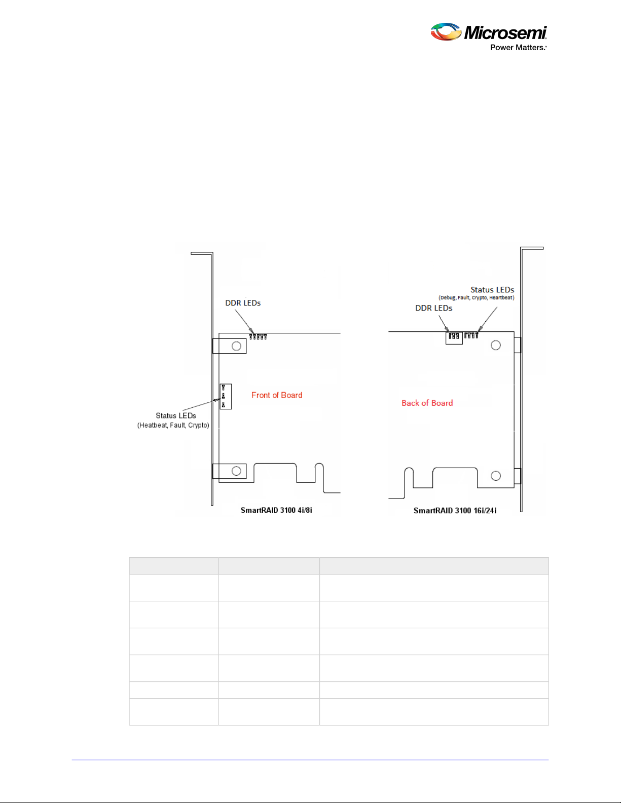
3.3 Visual Indicators
LEDs on SmartRAID 3100 Series adapters provide a visual indication of the board hardware status and
cache backup system. SmartRAID 3100-4i and -8i adapters include status LEDs near the mounting bracket
and DDR LEDs (also referred to as Flash-Based Write Cache, or FBWC, LEDs) at the top of the printed
circuit board. On SmartRAID 3100-16i and -24i adapters, the LEDs are located on the back of the board
(see Figure 1 • SmartRAID 3100 Series LED Locations). The LED states are described below in Table 2 •
SmartRAID 3100 Series Status LEDs and Table 3 • SmartRAID 3100 Series DDR/FBWC LED States.
Front panel brackets on SmartRAID 3100-4i/8i controllers have three holes for the Heartbeat LED, Fault
LED, and Crypto LED.
Figure 1 • SmartRAID 3100 Series LED Locations
Table 2 • SmartRAID 3100 Series Status LEDs
YellowDDR_LED1
GreenDDR_LED2
GreenDDR_LED3
GreenHEARTBEAT
GreenCRYPTO
MeaningColorLED
Cache backup error (see Table 3 • SmartRAID 3100 Series
DDR/FBWC LED States)
Dirty cache (see Table 3 • SmartRAID 3100 Series DDR/FBWC
LED States)
Charge status (see Table 3 • SmartRAID 3100 Series DDR/FB-
WC LED States)
Heartbeat (blinks once per/second when rmware operating
normally)
Hardware Lockup/FaultYellowFAULT
Cryptographic State: Off= NON-ENCRYPTING, On = ENCRYPTING
17CONFIDENTIAL Installation and User's Guide Issue 1
Page 18
About Your SmartRAID 3100 Series Host Bus Adapter
GreenAVS_ENB
MeaningColorLED
The controller is operating normally if this LED is on or off:
On = Adaptive Voltage Scaling (AVS) Enabled, Off = Adaptive
Voltage Scaling (AVS) Disabled
Note: Not supported on SmartRAID 3100-16i and
SmartRAID 3100-24i adapters.
PAL_DEBUG
Red (16i/24i adapters)
Debug LED control signalYellow (8i/8e adapters)
Table 3 • SmartRAID 3100 Series DDR/FBWC LED States
Cache Status
Cache powered Off
State
POWER not ready
POWER ready, No
dirty Cache
POWER ready, Dirty
Cache
State
State
BROWNOUT & BAD_
VOLT
VOLT
er timeout
Sate ASIC Error
DDR_LED1
(Yellow)
DDR_LED2
(Green)
INFORMATIONAL: Amber LED Off
ERROR: Amber LED On or Blinking
(Green)
Blinking 1/2HzBlinking 1/2HzOffBoot loader/Program
Blinking 1HzBlinking 1HzOffPower Up State
Blinking 1HzOffOffIdle State, BACKUP
OnOffOffIdle State, BACKUP
OnOnOffIdle State, BACKUP
OffBlinking 1HzOffBackup State
OffOnOffBackup Complete
Blinking 1HzOnOffBackup State Cont.
OffBlinking 1HzBlinking 1HzIdle State & BDtF &
OnBlinking 1HzBlinking 1HzIdle State & BAD_
OnBlinking 2HzBlinking 2HzIdle State, Capcharg-
OnOnOnCache Error
Meaning/CommentsDDR_LED3
Controller/cache is not powered.OffOffOff
Data retention inprocess, system power
is available.
Indicates PIC Backup Error: PIC unable
to complete the backup on a previous
Panic.
Indicates BAD_VOLT either set on a
previous boot or during current boot by
the PIC. Data may be corrupted.
OVER_TEMP_ALERT is set.OffOnBlinking 1HzOver-temperature
Indicates ASIC Backup Error.OffOnOnBackup Complete
Error detected: PIC failed to load bootloader, main code checksum failed, stuck
in bootloader, other failure.
18CONFIDENTIAL Installation and User's Guide Issue 1
Page 19
About Your SmartRAID 3100 Series Host Bus Adapter
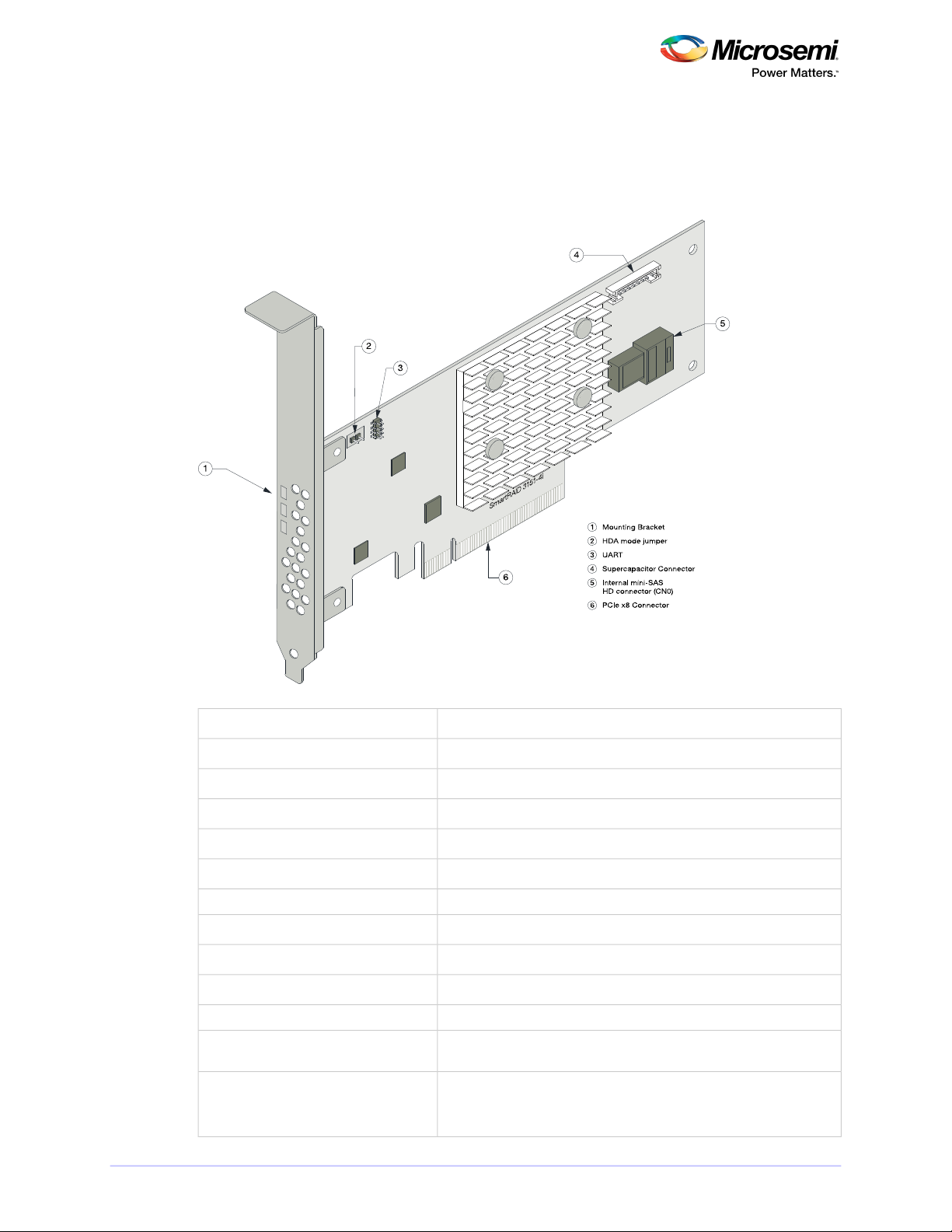
3.4 About the Microsemi Adaptec SmartRAID 3101-4i/3151-4i
The Microsemi Adaptec SmartRAID 3101-4i/3151-4i is a SAS Host Bus Adapter with these features:
Figure 2 • Microsemi Adaptec SmartRAID 31x1-4i
Thermal sensor
Low-prole MD2Form Factor
PCIe 3.0Bus compatibility
x8PCIe bus width
12 Gb/s per portData transfer rate
4Phys (Unied Serial Ports)
32 MB Boot Flash, 256 Kb SEEPROM, 1Mb MRAMStandard memory
1 GBCache
1 mini-SAS HD x4 (SFF-8643)Connectors, internal
4 direct-attached (or up to 238 with expanders)Maximum number of disk drives
SES2, SES3, IBPI and SGPIOEnclosure Support
NoEncryption
Inlet ambient temperature, ASIC die temperature, Top-side board ambient temperature, Bottom-side board ambient temperature
SmartRAID 3101-4i: NoCache Protection/Backup
SmartRAID 3151-4i: Integrated ASCM-35F backupmodule with external
supercapacitor
19CONFIDENTIAL Installation and User's Guide Issue 1
Page 20
About Your SmartRAID 3100 Series Host Bus Adapter
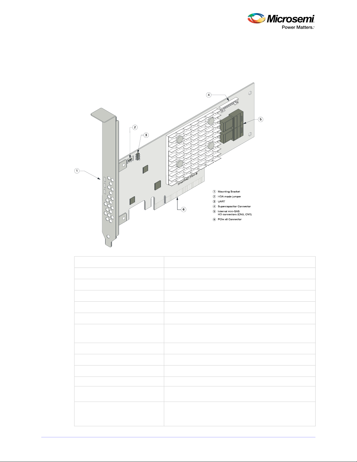
3.5 About the Microsemi Adaptec SmartRAID 3102-8i/3152-8i/3154-8i
The Microsemi Adaptec SmartRAID3102-8i/3152-8i/3154-8iis a SAS Host Bus Adapter with these features:
Figure 3 • Microsemi Adaptec SmartRAID 31xx-8i
Thermal sensor
Low-prole MD2Form Factor
PCIe 3.0Bus compatibility
x8PCIe bus width
12 Gb/s per portData transfer rate
8Phys (Unied Serial Ports)
32 MB Boot Flash, 256 Kb SEEPROM, 1Mb MRAMStandard memory
SmartRAID 3102-8i/3152-8i: 2 GBCache
SmartRAID 3154-8i: 4 GB
2 mini-SAS HD x4 (SFF-8643)Connectors, internal
8 direct-attached (or up to 238 with expanders)Maximum number of disk drives
SES2, SES3, IBPI and SGPIOEnclosure Support
YesEncryption
Inlet ambient temperature, ASIC die temperature, Top-side board ambient temperature, Bottom-side board ambient temperature
SmartRAID 3102-8i: NoCache Protection/Backup
SmartRAID 3152-8i/3154-8i: Integrated ASCM-35F backup module with
external supercapacitor
20CONFIDENTIAL Installation and User's Guide Issue 1
Page 21
About Your SmartRAID 3100 Series Host Bus Adapter
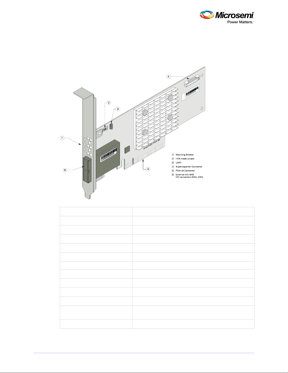
3.6 About the Microsemi Adaptec SmartRAID 3154-8e
The Microsemi Adaptec SmartRAID 3154-8e is a SAS Host Bus Adapter with these features:
Figure 4 • Microsemi Adaptec SmartRAID 3154-8e
Thermal sensor
Low-prole MD2Form Factor
PCIe 3.0Bus compatibility
x8PCIe bus width
12 Gb/s per portData transfer rate
8Phys (Unied Serial Ports)
32 MB Boot Flash, 256 Kb SEEPROM, 1 Mb MRAMStandard memory
4 GBCache
2 mini-SAS HD x4 (SFF-8644)Connectors, external
8 direct-attached (or up to 238 with expanders)Maximum number of disk drives
SES2, SES3, IBPI and SGPIOEnclosure Support
NoEncryption
Inlet ambient temperature, ASIC die temperature, Top-side board ambient temperature, Bottom-side board ambient temperature
Integrated ASCM-35F backup module with external supercapacitorCache Protection/Backup
21CONFIDENTIAL Installation and User's Guide Issue 1
Page 22
About Your SmartRAID 3100 Series Host Bus Adapter
3.7 About the Microsemi Adaptec SmartRAID 3154-16i
The Microsemi Adaptec SmartRAID 3154-16i is a SAS Host Bus Adapter with these features:
Figure 5 • Microsemi Adaptec SmartRAID 3154-16i
Low-prole MD2Form Factor
PCIe 3.0Bus compatibility
x8PCIe bus width
12 Gb/s per portData transfer rate
16Phys (Unied Serial Ports)
32 MB boot ash, 128 Kb SEEPROM, 128 KB MRAMStandard memory
4 GBCache
4 mini-SAS HD x4 (SFF-8643)Connectors, internal
16 direct-attached (or up to 238 with expanders)Maximum number of disk drives
SES2, SES3, IBPI and SGPIOEnclosure Support
Processor temperature, Ambient temperatureThermal sensor
Integrated ASCM-35F backup module with external supercapacitorCache Protection/Backup
22CONFIDENTIAL Installation and User's Guide Issue 1
Page 23

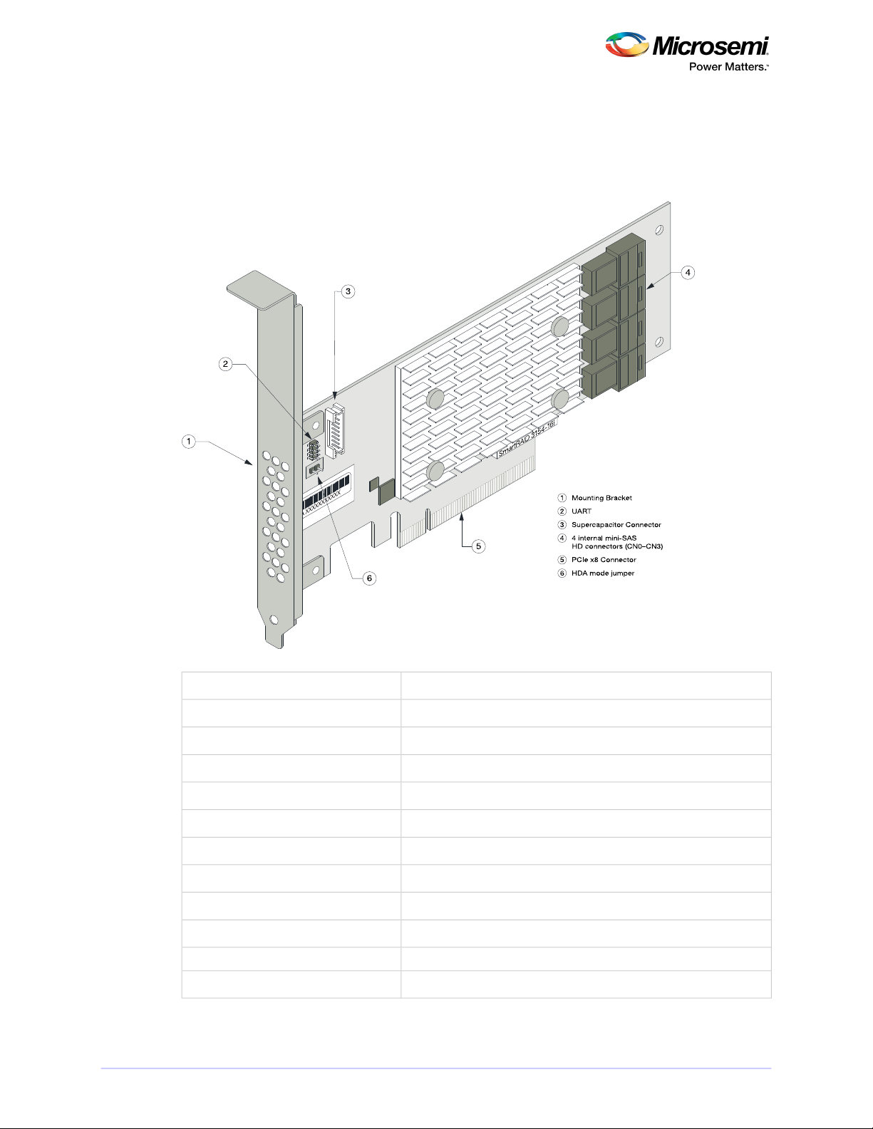
SmartRAID 3154-24i
1 Mounting Bracket
2 UART
3 Supercapacitor Connector
4 2 internal mini-SAS
HD connectors (CN4–CN5)
5 4 internal mini-SAS
HD connectors (CN0–CN3)
6 PCIe x8 Connector
7 HDA mode jumper
2
1
5
4
3
6
7
About Your SmartRAID 3100 Series Host Bus Adapter
3.8 About the Microsemi Adaptec SmartRAID 3154-24i
The Microsemi Adaptec SmartRAID 3154-24i is a SAS Host Bus Adapter with these features:
Figure 6 • Microsemi Adaptec SmartRAID 3154-24i
Low-prole MD2Form Factor
PCIe 3.0Bus compatibility
x8PCIe bus width
12 Gb/s per portData transfer rate
24Phys (Unied Serial Ports)
32 MB Boot Flash, 128 Kb SEEPROM, 128 KB MRAMStandard memory
4 GBCache
6 mini-SAS HD x4 (SFF-8643)Connectors, internal
24 direct-attached (or up to 238 with expanders)Maximum number of disk drives
SES2, SES3, IBPI and SGPIOEnclosure Support
Processor temperature, Ambient temperatureThermal sensor
Integrated ASCM-35F backup module with external supercapacitorCache Protection/Backup
23CONFIDENTIAL Installation and User's Guide Issue 1
Page 24

About Your SmartHBA 2100 Series Host Bus Adapter
4 About Your SmartHBA 2100 Series Host Bus Adapter
This section provides an overview of the features of the SmartHBA 2100 Series adapter.
4.1 Standard Features
• Support for SAS and SATA Hard Disk Drives (HDD) and Solid State Drives (SSD)
• uEFI pre-boot BIOS, CTRL-A conguration utility
• Flash ROM for updates to rmware and BIOS
• up to 8 ports (4 internal and 4 external), 12 Gbps I/O
• SAS 3.0, PCIe 3.0
• Low-prole MD2 form factor
• Mini-SAS HD connectors
• Support for disk drive enclosures with SES 2.x/3.x inband support, TWI, IBPI and SGPIO enclosure
management
• Thermal sensors, with logging capabilities
• Support for RAID 0, 1, 5, 10
4.2 Mechanical Information
4.2.1 Board Dimensions
This table shows the board dimensions of the SmartHBA 2100 Series adapters, in inches.
Table 4 • SmartHBA 2100 Series Board Dimensions
4.2.2 Heat Sink
SmartHBA 2100 Series adapters include a passive heat sink capable of bi-directional airow. The heat
sink does not support an optional fan. The heat sink has four push-pins located at its four corners to
ensure an even distribution of force across the top of the ASIC. For airow requirements, see
Environmental Specications.
SmartHBA 2100-8iSmartHBA 2100-4i4eDimension
2.712"2.70"Height
6.60"5.20"Length
0.062"0.062"PCB Thickness
0.570"0.570"Max Component Height, Top Side
0.105"0.105"Max Component Height, Bottom Side
24CONFIDENTIAL Installation and User's Guide Issue 1
Page 25

About Your SmartHBA 2100 Series Host Bus Adapter
4.3 Visual Indicators
SmartHBA 2100 Series adapters include status LEDs at the top of the printed circuit board and near the
mounting bracket. The LEDs signify the status of the actions described in Table 5 • SmartHBA2100 Series
Status LEDs.
Figure 7 • SmartHBA 2100 Series Status LEDs
Table 5 • SmartHBA 2100 Series Status LEDs
GreenHEARTBEAT (DS5)
GreenCRYPTO (DS1)
GreenAVS_ENB (DS2)
MeaningColorLED
Heartbeat (blinks once per second whenrmware is operating
normally)
Hardware Lockup/FaultYellowFAULT (DS7)
Cryptographic State: always off. SmartHBA 2100 Series
adapters do not support encryption.
On=Adaptive Voltage Scaling (AVS) enabled, Off=Adaptive
Voltage Scaling (AVS) disabled
Debug LED control signalRedPAL_DEBUG (DS10)
25CONFIDENTIAL Installation and User's Guide Issue 1
Page 26

About Your SmartHBA 2100 Series Host Bus Adapter
4.4 About the Microsemi Adaptec SmartHBA 2100-4i4e
The Microsemi Adaptec SmartHBA 2100-4i4e is a SAS Host Bus Adapter with these features:
Figure 8 • Microsemi Adaptec SmartHBA 2100-4i4e
Thermal sensors
PCIe Low-prole MD2 (smaller than MD2)Form Factor
PCIe 3.0Bus compatibility
x8PCIe bus width
12 Gbps per portData transfer rate (SAS)
8Phys (Unied Serial Ports)
32 MB Boot Flash, 16 KB SEEPROM, 128 KB MRAMStandard memory
1x1 mini-SAS HD x4 (SFF-8643)Connectors, internal
1x1 mini-SAS HD x4 (SFF-8644)Connectors, external
4/port direct-attached (or up to 238 with expanders)Maximum number of disk drives
SES 2.x/3.x inband support, TWI, IBPI and SGPIOEnclosure Support
Inlet ambient temperature, ASIC die temperature, Top-side board ambient temperature, Bottom-side board ambient temperature
26CONFIDENTIAL Installation and User's Guide Issue 1
Page 27

About Your SmartHBA 2100 Series Host Bus Adapter
4.5 About the Microsemi Adaptec SmartHBA 2100-8i
The Microsemi Adaptec SmartHBA 2100-8i is a SAS Host Bus Adapter with these features:
Figure 9 • Microsemi Adaptec SmartHBA 2100-8i Features
Thermal sensors
PCIe Low-prole MD2 (smaller than MD2)Form Factor
PCIe 3.0Bus compatibility
x8PCIe bus width
12 Gbps per portData transfer rate (SAS)
8Phys (Unied Serial Ports)
32 MB Boot Flash, 32 KB SEEPROM, 128 KB MRAMStandard memory
1x2 mini-SAS HD x4 (SFF-8643)Connectors, internal
4/port direct-attached (or up to 238 with expanders)Maximum number of disk drives
SES 2.x/3.x inband support, TWI, IBPI and SGPIOEnclosure Support
Inlet ambient temperature, ASIC die temperature, Top-side board ambient temperature, Bottom-side board ambient temperature
27CONFIDENTIAL Installation and User's Guide Issue 1
Page 28

About Your SmartHBA 2100 Series Host Bus Adapter
4.6 About the Microsemi Adaptec SmartHBA 2100-24i
The Microsemi Adaptec SmartHBA 2100-24i is a SAS Host Bus Adapter with these features:
Figure 10 • Microsemi Adaptec SmartHBA 2100-24i Features
PCIe Low-prole MD2Form Factor
PCIe 3.0Bus compatibility
x8PCIe bus width
12 Gbp/s per portData transfer rate (SAS)
24Phys (Unied Serial Ports)
32 MB Boot Flash, 16 KB SEEPROM, 128 KB MRAMStandard memory
6 mini-SAS HD x4 (SFF-8643)Connectors, internal
24 direct-attached (or up to 238 with expanders)Maximum number of disk drives
SES 2.x/3.x inband support, TWI, IBPI and SGPIOEnclosure Support
Inlet ambient temperature, ASIC die temperatureThermal sensors
28CONFIDENTIAL Installation and User's Guide Issue 1
Page 29

Installing the Controller and Disk Drives
5 Installing the Controller and Disk Drives
This section explains how to install your SmartRAID 3100 Series or SmartHBA 2100 Series adapter in a
computer cabinet or server and connect it to internal and external disk drives.
5.1 Before You Begin
• Read Safety Information.
• Familiarize yourself with your host bus adapter's physical features (see Standard Features).
• Ensure that you have the right number of disk drives for your application (see Selecting Disk Drives
and Cables).
5.2 Selecting Disk Drives and Cables
5.2.1 Disk Drives
Your SmartRAID 3100 Series or SmartHBA 2100 Series adapter supports SAS and SATA disk drives, Solid
State Drives (SSDs), and SAS tape drives. For more information about compatible disk drives, refer to
http://www.microsemi.com/products/storage/compatibility.
5.2.2 Cables
Depending on your adapter model and application requirements, you can use any of the cables listed
below. For more information about cabling options for your SmartRAID 3100 Series or SmartHBA 2100
Series adapter, visit www.microsemi.com/products/storage/cables-accessories.
Note: We recommend using Microsemi Adaptec SAS cables only.
SAS HD Cables
Internal Mini SAS HD to SAS HD (SFF-8643 to SFF- 8643
)—Connects to a backplane or enclosure.
External Mini SAS HD to SAS HD (SFF-8644 to SFF- 8644
)—Connects to a backplane or enclosure.
29CONFIDENTIAL Installation and User's Guide Issue 1
Page 30

Installing the Controller and Disk Drives
5.3 Installing the Host Bus Adapter
This section describes how to install your SmartRAID 3100 Series or SmartHBA 2100 Series adapter in
a computer cabinet or server and connect internal and external storage devices. The SmartRAID 3100
Series and SmartHBA 2100 Series adapters have these congurations:
• Adapters with internal connectivity
• Adapters with external connectivity
• Adapters with internal and external connectivity
• Adapters with internal connectivity and an external supercapacitor module
1. Turn off your computer and disconnect the power cord and any network cables. Open the cabinet,
following the manufacturer's instructions.
2. Select an available PCIe expansion slot that's compatible with your adapter model and remove the
slot cover, as shown in the gure below. (To check PCIe bus compatibility of your adapter, see About
Your Host Bus Adapter.)
Note: For SmartRAID 3100 Series adapters with an external supercapacitor module, select a
slot for the adapter that's next to an empty slot in the backplane, ideally, a short.
Caution: Touch a grounded metal object before handling the adapter.
3. Insert the adapter into the expansion slot and press down gently but rmly until it clicks into place.
When installed properly, the adapter should appear level with the expansion slot.
Caution: Be sure to handle the adapter by its bracket or edges only. Apply pressure only on
the edges when inserting the card into expansion slot.
30CONFIDENTIAL Installation and User's Guide Issue 1
Page 31

Installing the Controller and Disk Drives
4. Secure the bracket in the expansion slot, using the retention device (for instance, a screw or lever)
supplied with your computer.
5. Connect SAS HD cables between the adapter and internal or external storage devices, as required:
• For adapters with internal ports, connect SAS HD cables between the adapter and internal disk
drives or enclosures:
• For adapters with external ports, connect SAS HD cables between the adapter and external disk
drives or enclosures:
31CONFIDENTIAL Installation and User's Guide Issue 1
Page 32

External Port,
Front view
Internal Port
Installing the Controller and Disk Drives
• For adapters with with internal and external ports, connect SAS HD cables between the adapter
and internal and external disk drives or enclosures:
6. (For SmartRAID 3100 Series adapters with external supercapacitor module only) Referto theMicrosemi
Adaptec Flash Backup Module ASCM-35 Installation Instructions (ESC-2170352) to complete the
installation of the supercapacitor module.
7. Close your computer cabinet, reconnect the power cord and network cables, then power up the
system.
32CONFIDENTIAL Installation and User's Guide Issue 1
Page 33

Installing the Driver and an Operating System
6 Installing the Driver and an Operating System
This chapter explains how to install the Microsemi SmartPQI controller driver and an operating system
on a bootable volume. It assumes that the SmartHBA 2100/SmartRAID 3100 controller is installed in a
computer or server.
Note:
• For information about building the SmartPQI drivers from source, see Installing the SmartPQI
Drivers from Source on page 65.
6.1 Download the Driver Package
Complete these steps to download the drivers for your operating system(s):
1. Open a browser window, then type start.microsemi.com in the address bar.
2. Enter your product or adapter model number, then select SmartRAID 3100 or SmartHBA 2100.
3. Select your operating system version, for instance, Microsoft Windows Server 2016 x64 or Red Hat
Enterprise Linux 7; then select the appropriate driver from the list.
4. Download the controller driver package (zip le archive).
5. When the download completes, extract the package contents to a temporary location on your
machine. Each driver is stored in a separate folder (\windows 2016, \rhel7, \rhel6, and so on).
Note: See the Release Notes for a complete list of available driver les.
6.2 Creating a Driver Disk
Create a driver disk by completing the steps below. You will need a USB ash drive to complete this
task.
Note: For VMware, see Installing with VMware on page 43.
1. Change to the driver directory for your operating system version.
2. Write the driver binary le to a USB ash drive.
For example, if the USB drive is /dev/sdc on the Linux system, type (where #.#.#-### is the build
number):
DescriptionOptions
dd if=smartpqi-#.#.#-###.rhel7u2.x86_64.dd of=/dev/sdcRHEL 7
dd if=smartpqi-#.#.#-###.sles12sp1.x86_64.dd of=/dev/sdcSLES 12
dd if=smartpqi-#.#.#-###_ubuntu16.04_x86_64.img of=/dev/sdcUbuntu
dd if=smartpqi-#.#.#-###.ol7u2.x86_64.dd of=/dev/sdcOracle Linux 7
Debian Linux
Note: See the Release Notes for the latest build number.
3. Remove and label the driver disk.
4. Continue the installation with the instructions for your operating system.
dd if=smartpqi-#.#.#-###_debian8.8_x86_64-Boot.tgz of=/dev/
sdc
6.3 Installing with Windows
Note: Use the following procedure for all supported Windows versions. You will need your
Windows Installation DVD (or equivalent virtual media/iso image) to complete this task.
33CONFIDENTIAL Installation and User's Guide Issue 1
Page 34

Installing the Driver and an Operating System
To install the controller SmartPQI driver while installing Windows:
1. Insert the Windows installation DVD, then restart the computer.
2. Follow the on-screen instructions to begin the Windows installation.
3. When prompted to specify a location for Windows, select Load Driver.
4. Insert the USB driver disk, browse to the driver location, then click Ok.
5. When prompted to select the driver to install, click Next.
6. Click Next again to accept the default partition conguration.
7. Follow the on-screen instructions to complete the installation.
6.4 Installing with Red Hat Linux or CentOS
To install the controller SmartPQI driver while installing Red Hat Linux or CentOS, follow the steps in
the sections below.
RHEL7 Update 3 Installation and Above
To install the RHEL7 Update 3 driver with a Linux system:
1. Install the Linux system using the inbox smartpqi driver.
2. After theinstallation completes, install the latest smartpqi driverrpm byusing thefollowing command
(where #.#.#-### is the build number):
rpm –ivh kmod-smartpqi-#.#.#-###.rhel7u3.x86_64.rpm
RHEL7 Installation
Note: The following steps applyto all updates of RHEL 7 prior to Update3. Theexample illustrated
here represents the steps for Update 2. Modify the lename of the installation archive to match
the appropriate update version in the appropriate elds.
To install the RHEL7 driver with a Linux system:
1. Copy the RHEL driver binary image to the USB key; see Creating a Driver Disk on page 33.
2. Power-on the system.
3. Insert the RHEL7 DVD image from a media source.
4. Boot the RHEL installation.
5. Type "e" to edit the grub entry and append "modprobe.blacklist=aacraid inst.dd".
Note: This will cause the line to wrap. The editor adds the "\" automatically.
6. Insert the USB device, then type CTRL+X to boot.
Note: If the installer does not display the driver update media, type "r" and Enter on your
keyboard to refresh the list.
a. Select the device in the list with the label "OEMDRV":
The installer presents a driver (smartpqi rpm) to install.
b. Type "1" on your keyboard and Enter to select the driver update.
c. Type "c" and Enter to continue.
Note: It is recommended to remove the USB device once the driver update has been
extracted, for example:
DD: Extracting files....
34CONFIDENTIAL Installation and User's Guide Issue 1
Page 35

Installing the Driver and an Operating System
RHEL6 Update 9 Installation and Above
To install the RHEL6 Update 9 driver with a Linux system:
1. Install the Linux system using the inbox smartpqi driver.
2. After theinstallation completes, install the latest smartpqi driverrpm byusing thefollowing command
(where #.#.#-### is the build number):
rpm –ivh smartpqi-kmp-default-#.#.#-###.rehl6u9.x86_64.rpm
RHEL6 Installation
To install the RHEL6 driver with a Linux system:
1. Copy the RHEL driver binary image to the USB key; see Creating a Driver Disk on page 33.
2. Power-on the system.
3. Insert the RHEL6 DVD image from a media source.
4. Boot the RHEL installation.
5. Press the Esc key when a grub entry appears with a countdown.
6. Type "e" to edit the grub entry
7. Type "e" again and append "blacklist=aacraid dd".
8. Press the Enter key and type "b".
9. Select Yes to specify that the driver disk is available.
10. Select the sd device.
Note: The device name of the driver update disk may vary.
11. Select No when the "More Driver Disks?" dialog appears.
Note: It is recommended to remove the USB device at this step.
12. Proceed with the normal installation.
6.5 Installing with SuSE Linux Enterprise Server
To install the controller SmartPQI driver while installing SuSE Linux, follow the steps in the sections
below.
Installing with SLES 12 SP2 and Above
Follow these steps to install the driver while installing SLES 12 SP2:
1. Install the Linux system using the inbox smartpqi driver.
2. After theinstallation completes, install the latest smartpqi driverrpm byusing thefollowing command
(where #.#.#-### is the build number):
rpm -ivh smartpqi-ueficert-#.#.#-###.sles12sp2.x86_64.rpm
rpm -ivh smartpqi-kmp-default-#.#.#-###.sles12sp2.x86_64.rpm
Installing with SLES 12
Follow these steps to install the driver while installing SLES 12:
1. Copy the SLES driver binary image to the USB key; see Creating a Driver Disk on page 33.
2. Power-on the system.
35CONFIDENTIAL Installation and User's Guide Issue 1
Page 36

Installing the Driver and an Operating System
3. Insert the SLES 12 DVD image from a media source.
4. Boot the SLES installation.
5. Type "e" to edit the grub entry when the SLES installation menu is displayed and append
"broken_modules=aacraid driverupdate=1".
6. Insert the USB device and type CTRL+X to boot.
The installation of the driver will start automatically.
7. Make sure that the controller is listed in the "Please choose the Driver Update medium" dialog box.
Note: If you do not see the controller, a driver installation error occurred. This can happen if
the driver was built against a different kernel version of the OS than the installed media.
Note: It is recommended to remove the driver update USB device.
8. Click Back and continue with the normal installation procedure.
Installing with SLES 11
Follow these steps to install the driver while installing SLES 11:
1. Copy the SLES driver binary image to the USB key; see Creating a Driver Disk on page 33.
2. Power-on the system.
3. Insert the SLES 11 DVD image from a media source.
4. Boot the SLES installation.
5. Type "e" to edit the grub entry and append "broken_modules=aacraid driverupdate=1".
6. Insert the USB device and type CTRL+X to boot.
The installation of the driver will start automatically.
7. Make sure that the controller is listed in the "Please choose the Driver Update medium" dialog box.
Note: If you do not see the controller, a driver installation error occurred. This can happen if
the driver was built against a different kernel version of the OS than the installed media.
Note: It is recommended to remove the driver update USB device.
8. Click Back and continue with the normal installation procedure.
6.6 Installing with Oracle Linux
To install the controller SmartPQI driver while installing Oracle Linux, follow the steps in the sections
below.
Installing with Oracle Linux 7.3 and Above
Note:
1. The Oracle Linux 7.3 base kernel includes a smartpqi driver. The UEK kernel does not.
2. If using the UEK boot ISO for installation, you will need to use the driver update process
described in the Oracle Linux 7.2 installation section.
Follow these steps to install the driver while installing Oracle Linux 7.3:
1. Install the Linux system using the inbox smartpqi driver.
2. On reboot, select the Oracle Linux 7.3 base kernel from the grub menu to boot. Grub will attempt
to default to the UEK kernel.
3. After the installation completes, install the latest smartpqi driver rpm for the kernel you intend to
run (where #.#.#-### is the build number):
36CONFIDENTIAL Installation and User's Guide Issue 1
Page 37

Installing the Driver and an Operating System
Base Kernel: rpm –ivh kmod-smartpqi-#.#.#-###.ol7u3.x86_64.rpm
UEK Kernel: rpm –ivh kmod-smartpqi-uek-#.#.#-###.ol7u3.x86_64.rpm
Installing with Oracle Linux 7.2
Follow these steps to install the driver while installing Oracle Linux 7.2:
1. Copy the Oracle Linux driver binary image to the USB key; see Creating a Driver Disk on page 33.
2. Power-on the system.
3. Insert the Oracle Linux 7 DVD image from a media source.
4. Boot the Oracle installation.
5. Type "e" to edit the grub entry when the Oracle Linux installation menu is displayed and append
"modprobe.blacklist=aacraid inst.dd".
6. Insert the USB device, then type CTRL+X to boot.
The installation of the driver will start automatically.
7. Complete the following steps:
a. Select the device in the list with the label "OEMDRV".
The installer will present a driver (smartpqi rpm) to install.
b. Type "1" on your keyboard, then press Enter to select the driver update.
c. Type "c", then press Enter to continue.
Note: We recommend that you remove the USB device once you see thatthe driver update
has been extracted; for example: "DD: Extracting files...".
d. Click Continue and follow the prompts for a normal install.
Note: The driver update will install the smartpqi driver for the Oracle Linux 7.2 base kernel
only.
8. On reboot, select the Oracle Linux 7.2 base kernel from the grub menu to boot. Grub will attempt
to default to the UEK kernel.
9. After the installation completes, install the latest smartpqi driver rpm for the UEK kernel (where
#.#.#-### is the build number):
UEK Kernel: rpm –ivh kmod-smartpqi-uek-#.#.#-###.ol7u2.x86_64.rpm
6.7 Installing with Ubuntu Linux
To install the controller SmartPQI driver while installing Ubuntu Linux:
1. Copy the Ubuntu driver binary image to the USB key; see Creating a Driver Disk on page 33.
2. Power-on the system.
3. Insert the Ubuntu CD/DVD image from a media source.
4. Boot the Ubuntu installation.
5. Type "e" to edit the grub entry when the Ubuntu installation menu is displayed.
6. Append "modprobe.blacklist=aacraid" after the “--“ on the line starting with “Linux”.
7. Insert the USB device, then type CTRL+X to boot.
The driver installation will start automatically.
8. When the installer presents a dialog regarding detection of a virtual driver disk, select yes. Then
proceed with standard installation process.
37CONFIDENTIAL Installation and User's Guide Issue 1
Page 38

Installing the Driver and an Operating System
Note: It is recommended to remove the driver update USB device when the installer reaches
the “Congure the network” screen.
9. At the "Finish the installation/Installation complete" screen, from a back terminal blacklist the
aacraid driver before rebooting using the following steps:
a. Press Alt + F2.
b. Type the following commands:
chroot /target
echo “blacklist aacraid” > /etc/modprobe.d/install-aacraid.conf
depmod `uname –r`
update-initramfs –u
exit
c. Press Alt + F1 to return to the installation screen.
10. Press Continue to reboot the system.
11. Install the smartpqi DKMS package (smartpqi-dkms_#.#.#-###_all.deb) byusing thefollowing
commands (where #.#.#-### is the build number):
Note: The smartpqi DKMS package rebuilds the smartpqi driver automatically any time the
kernel on the system is updated. This insures you have a smartpqi driver to support the new
kernel.
apt-get update
apt-get –f install build-essential dkms
dpkg -i smartpqi-dkms_#.#.#-###_all.deb
6.8 Installing with Debian Linux
To install the controller SmartPQI driver while installing Debian Linux:
1. Copy the Debian driver binary image (smartpqi.ko) to the USB key; see Creating a Driver Disk on
page 33.
2. Boot the Debian installation from the DVD or media source.
3. Type "e" to edit the boot entry when the Debian installation menu is displayed.
4. Append "modprobe.blacklist=aacraid" after the “--“ on the line starting with “Linux”.
5. Type CTRL+X to boot.
6. Proceed with standard installation process until the installer reaches the “Congure the network”
screen.
7. Press CTRL+ALT+F2.
8. Insert the Debian driver USB key.
9. Assuming the USB drive is assigned to /dev/sda1, type the following commands to begin loading
the driver:
Note: Type fdisk -l to determine the USB device assignment.
mkdir /SMARTPQI
mount -t vfat /dev/sda1 /mnt
cp -R /mnt/* /SMARTPQI
umount /mnt
10. Remove the Debian driver USB key.
38CONFIDENTIAL Installation and User's Guide Issue 1
Page 39

Installing the Driver and an Operating System
11. Copy the driver to /lib/modules and load driver module:
Note: The following steps assume you are installing Debian 8.8 64-bit, using kernel 3.16.0-4.
mkdir -p /lib/modules/3.16.0-4-amd64/kernel/drivers/scsi/smartpqi
cp -f /SMARTPQI/smartpqi.ko
/lib/modules/3.16.0-4-amd64/kernel/drivers/scsi/smartpqi/smartpqi.ko
depmod -a `uname -r`
modprobe smartpqi
12. To return to the graphical install, press CTRL+ALT+F5; to return to a non-graphical install, press
ALT+F1.
Note: Do not press Continue at the end of the installation until you complete Step [13] and
Step [14].
13. When prompted to reboot the system, press CTRL+ALT+F2 to switch to the console.
14. Type the following commands to complete the driver installation:
mkdir -p /target/lib/modules/3.16.0-4-amd64/kernel/drivers/scsi/smartpqi
cp -f /SMARTPQI/smartpqi.ko
/target/lib/modules/3.16.0-4-amd64/kernel/drivers/scsi/smartpqi/smartpqi.ko
chroot /target
depmod -a `uname -r`
echo “blacklist aacraid” > /etc/modprobe.d/aacraid-blacklist.conf
update-initramfs -u -v
exit
15. To return to a graphical install, press CTRL+ALT+F5; to return to a non-graphical install, press ALT+F1.
16. Reboot the system.
17. Install the smartpqi DKMS package (smartpqi-dkms_#.#.#-###_all.deb) byusing thefollowing
commands (where #.#.#-### is the build number):
Note: The smartpqi DKMS package rebuilds and activates the smartpqi driver automatically
any time the kernel on the system is updated. This insures you have a smartpqi driver to
support the new kernel.
apt-get install build-essential dkms
dpkg -i smartpqi-dkms_#.#.#-###_all.deb
6.9 Installing with FreeBSD
To install the controller SmartPQI driver while installing FreeBSD:
1. Copy the driver module (smartpqi.ko) to a USB drive.
Disk partition the USB key, using gpart on a unix system.
For example:
# gpart create -s GPT da1
# gpart add -t freebsd-ufs da1
# newfs /dev/da1p1
# mount /dev/da1p1 /mnt
# cp smartpqi.ko /mnt
2. Insert the USB driver disk.
3. Insert the FreeBSD Installation disk into the CD/DVD drive and boot from it.
4. From the FreeBSD boot menu, press Escape to launch the boot loader prompt.
5. Perform the following steps at the boot loader prompt:
a. Check all the present modules by executing following command.
39CONFIDENTIAL Installation and User's Guide Issue 1
Page 40

Installing the Driver and an Operating System
# lsmod
Expected Output: It will show all the present modules.
b. Unload the kernel module by executing the following command:
# unload
c. Check whether the kernel is unloaded or not by executing the following command:
# lsmod
Expected Output: It will show all the present modules.
d. Check whether the USB drive is detected or not by executing the following command:
# lsdev
Expected Output:
part 0: ………….. (removable)
part 1: ………….. (removable)
part 2: ………….. (removable)
e. Load the kernel by executing the following command:
# load /boot/kernel/kernel
f. Load the driver module by executing the following command:
# load part< USB key location >:smartpqi.ko
For example: # load part2:smartpqi.ko
g. Continue the Installation procedure by typing the following command and pressing Enter.
# boot
h. After completing the kernel installation and before rebooting the system, add the driver to the
new system. Choose "YES" when it prompts the following message for the manual conguration.
"The installation is now nished. Before exiting the installer, would you like to open a shell in the
new system to make any nal manual modications?
i. Use the following commands to complete the manual conguration:
a. Mount the USB key by using the following command:
# mount /dev/da1p1 /media
b. Copy the driver to the boot directory by using the following command:
# cp /media/smartpqi.ko /boot/modules/smartpqi.ko
c. Ensure that the boot loader loads by using the following command:
# vi /boot/loader.conf
d. Add the following line:
smartpqi_load="YES"
# reboot
6. If the system halts at # mountroot>, check for the boot partition using the following command:
40CONFIDENTIAL Installation and User's Guide Issue 1
Page 41

Installing the Driver and an Operating System
# mountroot> ?
Note: The boot partition is primarily present in P2, so use the following command:
# mountroot> ufs:/dev/<da0p2>
6.10 Installing with Solaris
To install the controller SmartPQI driver while installing Solaris, follow the steps in the sections below.
6.10.1 Installing with Solaris Live Media
To install the SmartPQI controller driver with Solaris Live Media:
1. Copy the smartpqi.pkg or iso le and adddriver.sh le to a USB ash drive and insert that
drive into the installation system (see Creating a Driver Disk on page 33).
2. Boot to the Solaris 11 live media DVD in the installation system. Select the Solaris version and press
Enter.
3. Select the keyboard (default is 27) and language (default is 3).
4. Enter your login credentials.
The GUI will appear.
5. Open the terminal and switch to the root user by using the following command:
# su
Use "solaris" as the root password.
6. Microsemi controllers are claimed with the inbox aac driver so, it is necessary to remove the driver.
Use the following command to remove the inbox aac driver:
# rem_drv aac
7. Open the "Device driver utility" from the desktop and enter the root password.
8. The DD utility scans and automatically highlights the controller or devices that are not claimed by
the driver.
9. Click Browse to load the driver image from the USB ash drive.
10. Select smartpqi.pkg or iso le and click "OK".
11. Click Install.
The Installation Successful message gets displayed.
12. The DD utility rescans the devices.
13. The available disks are viewable in the terminal by typing the format command. Press CtrlL+C to
return to the command prompt.
14. Return to the desktop by typing exit at the ~# prompt.
15. Double click the Install Oracle Solaris icon for OS installation and follow the steps to complete the
OS installation.
Note: After the OS is installed, perform following procedure:
1. Open the terminal and copy the adddriver.sh le to /tmp directory.
# cp /media/USB_DRIVE/adddriver.sh /tmp/
# cd /tmp
41CONFIDENTIAL Installation and User's Guide Issue 1
Page 42

Installing the Driver and an Operating System
2. Execute the adddriver.sh script le with the parameter live as follows:
# chmod +x adddriver.sh
# ./adddriver.sh live
3. Reboot the system using the following command:
# reboot
6.10.2 Installing with Solaris Text Installer
To install the SmartPQI driver with Solaris Text Installer:
1. Copy the smartpqi.pkg or iso le and adddriver.sh les to a USB ash drive and plug that
drive into the installation system (see Creating a Driver Disk on page 33).
2. Boot to the Solaris 11.3 text installer DVD in the installation system, and select the keyboard and
language.
3. After the DVD boots, select option 3 (Shell) from the list.
4. Remove the inbox aac driver and exit the shell using the following commands:
#rem_drv aac
#exit
5. Select option 2 (Install Additional Drivers) from the list. The Device Driver Utility screen appears.
6. Press the F4 key (Media) to search for the driver image le on your ash drive.
7. Select USB drive and press Enter.
8. Find the location of the smartpqi.pkg or iso le on the ash drive, highlight it, nd press the F2
key to select it.
9. Press the F2 key again to install the driver.
10. If the installation succeeds, the following screen will appear:
11. Press the F9 key to exit to the Options menu.
42CONFIDENTIAL Installation and User's Guide Issue 1
Page 43

Installing the Driver and an Operating System
12. Select option 3 (Shell ) from the list.
13. Type the format command in the terminal window to list the available disks. Press Ctrl+C to return
to the command prompt.
14. Type exit at the ~# prompt to go back to the Options menu.
15. Enter option 1 to Install Oracle Solaris.
The Welcome to Oracle Solaris screen appears.
16. Press the F2 key to continue.
17. Select the disk discovery method and press the F2 key to continue.
18. Follow installation steps accordingly.
19. At the installation summary, press the F2 key to install the Oracle package; or, press the F3 key to
go back to make changes.
20. After the OS has been installed, press F9 to go back to the Options menu.
21. Select Option 3 (Shell).
22. Open the terminal andcopy the adddriver.shle to /tmp directory usingthe following commands:
# cp /media/USB_DRIVE/adddriver.sh /tmp/
# cd /tmp
23. In the terminal, execute the adddriver.sh script le with the parameter text as follows:
# chmod +x adddriver.sh
# ./adddriver.sh text
24. Reboot the system using the following command:
#reboot
6.11 Installing with Citrix XenServer
Note: For XenServer 7.1 and later, a USB key is supported for the driver update ISO. On a Linux
system, use the dd command to write the SmartPQI driver ISO image to the USB key (see Creating
a DriverDisk on page 33). Youneed the XenServer installation DVD (or equivalent virtual media/iso
image) to complete this task. You must have administrator privilege to install the driver image.
To install the controller SmartPQI driver while installing Citrix XenServer:
1. On the machine whereyou want to install the OSand SmartPQIdriver, insert theXenServer installation
DVD, then restart your computer.
2. When prompted to add a driver, insert the driver USB key, press F9, then select local media.
Note: Leave the driver USB key inserted throughout the installation.
3. Verify the SmartPQI driver and “use”.
4. Continue the XenServer installation, following the on-screen instructions.
5. Remove the driver USB key, then reboot your computer.
6.12 Installing with VMware
Note: You will need a writable CD or USB ash drive to complete this task. You must have
administrator privileges to create the driver disk and install the driver image.
43CONFIDENTIAL Installation and User's Guide Issue 1
Page 44

Installing the Driver and an Operating System
To install the controller SmartPQI driver with VMware ESXi 6.0 or VMware ESXi 6.5, you must create a
custom boot image using the ESXi-Customizer tool. This tool automates the process of customizing the
ESXi install-ISO and runs as a script under Microsoft PowerShell.
You can download the ESXi-Customizer tool, ESXi-Customizer-PS-v2.5.ps1, from
https://www.v-front.de/p/esxi-customizer-ps.html and other locations on the Web.
Note: Be sure to install the prerequisite software rst, including Powershell and VMware
POWERCLI, before you install ESXi-Customizer.
To install the SmartPQI controller driver while installing VMware:
1. Download and install Microsoft PowerShell and VMware POWERCLI, as needed. You can download
PowerShell from the Microsoft Download Center at www.microsoft.com/download, and POWERCLI
from my.vmware.com.
Note: PowerShell is pre-installed on many Windows systems, including Windows Server 2012
and Windows Server 2016.
2. Download the ESXi-Customizertool from https://www.v-front.de/p/esxi-customizer-ps.html orother
Web location. Then, unpack the archive to a local directory on your Windows system;
C:\ESXi-Customizer, for instance.
3. Copy the VMware driver vib for your OS version to a temp directory, such as C:\temp\pkg. The
driver vib les (listed below, where xxxxxxx is the driver version number) should be in the driver
download directory on your Windows system (see Creating a Driver Disk on page 33).
DescriptionOptions
smartpqi-1.0.0.1044-1OEM.650.0.0.xxxxxxx.x86_64.vibESXi 6.5
smartpqi-1.0.0.1044-1OEM.600.0.0.xxxxxxx.x86_64.vibESXi 6.0
4. Run ESXi-Customizer from the installation directory:
C:\ESXi-Customizer>ESXi-Customizer.cmd
5. In PowerShell, enter the following command:
.\ESXi-Customizer-PS-v2.5.ps1 –Vxx -pkgDir C:\temp\pkg
where Vxx is the VMware OS version: V60 for VMmare 6.0, V65 for VMware 6.5.
PowerShell begins creating the custom ESXi install-ISO with embedded SmartPQI driver. It displays
"All done" when the ISO is ready.
6. Burn the custom ISO image to a writable CD or USB drive.
Note: Use whatever tool you prefer to burn the CD or USB drive.
Remove the CD or USB drive after you nish burning the image.
7. On the VMware ESXi machine, insert the custom boot CD/USB, then restart your computer.
8. Follow the on-screen instructions to begin the VMware installation.
9. Complete the VMware installation, following the on-screen instructions.
10. Remove the custom boot CD or USB drive, then reboot your computer.
44CONFIDENTIAL Installation and User's Guide Issue 1
Page 45

Installing the Driver on an Existing Operating System
7 Installing the Driver on an Existing Operating System
This chapter explains how to install the Microsemi SmartPQI controller driver on an existing operating
system. It assumes that the SmartHBA 2100/SmartRAID 3100 controller is installed in a computer or
server and the OS is already installed.
Note:
• To install the driver while you're installing an operating system, see Installing the Driver and
an Operating System.
• For information about building the SmartPQI drivers from source, see Installing the SmartPQI
Drivers from Source on page 65.
7.1 Download the Driver Package
Complete these steps to download the drivers for your operating system(s):
1. Open a browser window, then type start.microsemi.com in the address bar.
2. Enter your product or adapter model number, then select SmartRAID 3100 or SmartHBA 2100.
3. Select your operating system version, for instance, Microsoft Windows Server 2016 x64 or Red Hat
Enterprise Linux 7; then select the appropriate driver from the list.
4. Download the controller driver package (zip le archive).
5. When the download completes, extract the package contents to a temporary location on your
machine. Each driver is stored in a separate folder (\windows 2016, \rhel7, \rhel6, and so on).
Note: See the Release Notes for a complete list of available driver les.
7.2 Creating a Driver Disk
Create a driver disk by completing the steps below. You will need a USB ash drive to complete this
task.
1. Change to the driver directory for your operating system version.
2. Write the driver binary le to a USB ash drive.
3. Remove and label the driver disk.
4. Continue the installation with the instructions for your operating system.
7.3 Installing on Windows
Note: The following instructions apply to all supported Windows operating systems.
To install the controller SmartPQI driver on Windows:
1. Start or restart Windows.
2. In the Control Panel, launch the Device Manager, right-click your Smart Storage Controller, then
select Update Driver Software.
3. Insert the driver disk, then select Browse my computer for driver software.
4. Browse to the driver disk location, then click Next.
5. Select the driver from the list, then click Next.
6. Specify the device type as a Storage controller and click Next.
7. Select the device driver you want to install.
8. Navigate to the disk location where the driver les are copied.
9. When the installation is complete, remove the driver disk and restart your computer.
45CONFIDENTIAL Installation and User's Guide Issue 1
Page 46

Installing the Driver on an Existing Operating System
7.4 Installing on Red Hat or CentOS
To install the controller SmartPQI driver on Red Hat Linux or CentOS, follow the steps in the sections
below.
Note: The inbox aacraid driver is available in many of the Linux distributions that include basic
support for Microsemi Adaptec Smart Storage Controllers, like the SmartHBA 2100/SmartRAID
3100 controller. The preferred driver is smartpqi. The followinginstructions show how to blacklist
the aacraid driver or replace it.
Installing on RHEL7 Update 3 and Above
Note: RHEL7 Update 3 includes a version of the smartpqi driver and an updated aacraid driver
that does not support the Microsemi Adaptec SmartHBA 2100/SmartRAID 3100 controller.
To install the RHEL7 Update 3 driver on a Linux system:
1. Install the latest smartpqi driver rpm by using the following command (where #.#.#-### is the build
number):
rpm –ivh kmod-smartpqi-#.#.#-###.rhel7u3.x86_64.rpm
Installing on RHEL 7
To install the RHEL7 driver on a Linux system:
1. Disable the aacraid support for the Smart Storage Controller using one of the following options:
• Using Blacklist Option:
Type the following command:
echo “blacklist aacraid” > /etc/modprobe.d/blacklist-aacraid.conf
• Update aacraid driver to allow Series 8 / HBA 1000 Controllers and SmartHBA 2100/SmartRAID
3100 controller to coexist:
1. Install an aacraid rpm version 1.2.1-53005 or higher using one of the following links:
https://storage.microsemi.com/en-us/support/series8/index.php
https://storage.microsemi.com/en-us/support/hba1000/index.php
2. Execute the following command:
rpm -Uvh kmod-aacraid-RHEL7.2-1.2.1-53005.x86_64.rpm
2. Install the latest smartpqi package by using the following command (where #.#.#-### is the build
number):
rpm –ivh kmod-smartpqi-#.#.#-###.rhel7u3.x86_64.rpm
Note: This command automatically rebuilds the initramfs with the updates, and avoids
rebuilding it manually.
Installing on RHEL6 Update 9 and Above
Note: RHEL6 Update 9 includes a version of the smartpqi driver and an updated aacraid driver
that does not support the Microsemi Adaptec SmartHBA 2100/SmartRAID 3100 controller.
To install the RHEL6 Update 9 driver on a Linux system:
1. Install the latest smartpqi driver rpm by using the following command (where #.#.#-### is the build
number):
rpm –ivh kmod-smartpqi-#.#.#-###.rhel6u9.x86_64.rpm
46CONFIDENTIAL Installation and User's Guide Issue 1
Page 47

Installing the Driver on an Existing Operating System
Installing on RHEL 6
To install the RHEL6 driver on a Linux system:
1. Disable the aacraid support for the Smart Storage Controller using one of the following options:
• Using Blacklist Option:
Type the following command:
echo “blacklist aacraid” > /etc/modprobe.d/blacklist-aacraid.conf
• Update aacraid driver to allow Series 8 / HBA 1000 Controllers and SmartHBA 2100/SmartRAID
3100 controller to coexist:
1. Install an aacraid rpm version 1.2.1-53005 or higher using one of the following links:
https://storage.microsemi.com/en-us/support/series8/index.php
https://storage.microsemi.com/en-us/support/hba1000/index.php
2. Execute the following command:
rpm -Uvh kmod-aacraid-RHEL6.8-1.2.1-53005.x86_64.rpm
2. Install the latest smartpqi package by using the following command (where #.#.#-### is the build
number):
rpm –ivh kmod-smartpqi-#.#.#-###.rhel6u8.x86_64.rpm
Note: This command automatically rebuilds the initramfs with the updates, and avoids
rebuilding it manually.
7.5 Installing on SuSE Linux Enterprise Server
To install the controller SmartPQI driver on SLES, follow the steps in the sections below.
Installing on SLES 12 SP2 and Above
Note: SLES 12 SP2 includes a version of the smartpqi driver and an updated aacraid driver that
does not support the Microsemi Adaptec SmartHBA 2100/SmartRAID 3100 controller.
Follow these steps to install the driver on SLES 12 SP2:
1. Install the latest smartpqi driver rpm by using the following command (where #.#.#-### is the build
number):
rpm -ivh smartpqi-ueficert-#.#.#-###.sles12sp2.x86_64.rpm
rpm -ivh smartpqi-kmp-default-#.#.#-###.sles12sp2.x86_64.rpm
Installing on SLES 12
Follow these steps to install the driver on SLES 12:
1. Disable the aacraid support for the Smart Storage Controller by using one of the following options:
• Using Blacklist Option:
Type echo “blacklist aacraid” > /etc/modprobe.d/blacklist-aacraid.conf
• Update aacraid driver to allow Series 8 / HBA 1000 Controllers and SmartHBA 2100/SmartRAID
3100 controller to coexist:
1. Install an aacraid rpm version 1.2.1-53005 or higher using one of the following links:
https://storage.microsemi.com/en-us/support/series8/index.php
https://storage.microsemi.com/en-us/support/hba1000/index.php
2. Execute the following command:
rpm -Uvh aacraid-kmp-default-SLES12-SP1-1.2.1-53005.x86_64.rpm
47CONFIDENTIAL Installation and User's Guide Issue 1
Page 48

Installing the Driver on an Existing Operating System
2. Install the latest smartpqi package by using the following command (where #.#.#-### is the build
number):
rpm -ivh smartpqi-ueficert-#.#.#-###.sles12sp1.x86_64.rpm
rpm -ivh smartpqi-kmp-default-#.#.#-###.sles12sp1.x86_64.rpm
3. Run “mkinitrd” command with the root user privilege to ensure that the blacklisting and driver
updates are included.
Installing on SLES 11
Note: The example illustrated here represents the steps for SLES 11 SP3. Modify the lename of
the installation archive to match the appropriate update version in the appropriate elds.
Follow these steps to install the driver on SLES 11:
1. Disable the aacraid support for the Smart Storage Controller by using one of the following options:
• Using Blacklist Option:
Type echo “blacklist aacraid” > /etc/modprobe.d/blacklist-aacraid.conf
• Update aacraid driver to allow Series 8 / HBA 1000 Controllers and SmartHBA 2100/SmartRAID
3100 controller to coexist:
1. Install an aacraid rpm version 1.2.1-53005 or higher using one of the following links:
https://storage.microsemi.com/en-us/support/series8/index.php
https://storage.microsemi.com/en-us/support/hba1000/index.php
2. Execute the following command:
rpm -Uvh aacraid-kmp-default-SLES11-SP3-1.2.1-53005.x86_64.rpm
2. Install the latest smartpqi package by using the following command (where #.#.#-### is the build
number):
rpm -ivh smartpqi-ueficert-#.#.#-###.sles11sp3.x86_64.rpm
rpm -ivh smartpqi-kmp-default-#.#.#-###.sles11sp3.x86_64.rpm
3. Run “mkinitrd” command with the root user privilege to ensure that the blacklisting and driver
updates are included.
7.6 Installing on Oracle Linux
To install the controller SmartPQI driver on Oracle Linux, follow the steps in the sections below.
Installing on Oracle Linux 7.3 and Above Running the Base Kernel
Note: The Oracle Linux 7.3 base kernel includes a smartpqi and an aacraid driver. The smartpqi
driver is recommended.
To install the SmartPQI driver on an Oracle Linux system:
1. Install the smartpqi driver rpm by using the followingcommand (where #.#.#-### is the build number):
rpm –ivh kmod-smartpqi-#.#.#-###.ol7u3.x86_64.rpm
Installing on Oracle Linux 7.2 running the Base or UEK Kernel and Oracle Linux
7.3 running the UEK Kernel
To install the SmartPQI driver on a Oracle Linux system:
1. Disable the aacraid support for the Smart Storage Controller using one of the following options:
• Using Blacklist Option:
Type the following command:
echo “blacklist aacraid” > /etc/modprobe.d/blacklist-aacraid.conf
48CONFIDENTIAL Installation and User's Guide Issue 1
Page 49

Installing the Driver on an Existing Operating System
• Update aacraid driver to allow Series 8 / HBA 1000 Controllers and SmartHBA 2100/SmartRAID
3100 controller to coexist:
1. Install an aacraid rpm version 1.2.1-53005 or higher using one of the following links:
https://storage.microsemi.com/en-us/support/series8/index.php
https://storage.microsemi.com/en-us/support/hba1000/index.php
2. Execute one of the following commands:
For Base Kernel: rpm -Uvh kmod-aacraid-OL7.2-1.2.1-53005.x86_64.rpm
For UEK Kernel: rpm -Uvh kmod-aacraid-UEK-OL7.2-1.2.1-53005.x86_64.rpm
2. Install the latest smartpqi package by using the following command (where #.#.#-### is the build
number):
For Base Kernel: rpm –ivh kmod-smartpqi-uek-#.#.#-###.ol7u2.x86_64.rpm
For UEK Kernel: rpm –ivh kmod-smartpqi-uek-#.#.#-###.ol7u2.x86_64.rpm
Note: This command automatically rebuilds the initramfs with the updates, and avoids
rebuilding it manually.
7.7 Installing on Ubuntu Linux
Note:
1. For driver installation on Ubuntu Linux, you may need to create the root account and password.
2. The SmartPQI driver is available as inbox for Ubuntu 16.04.3 Hardware Enablement kernel,
and above.
To install the controller SmartPQI driver on Ubuntu:
1. Login to the system using the root user credentials.
2. Update the Ubuntu package index by using the following command:
sudo apt-get update
3. Load the Ubuntu unpacking tools:
sudo apt-get –f install build-essential dkms
4. Disable the aacraid support for the Smart Storage Controller by using one of the following options:
• Using Blacklist Option:
Type the following command:
echo “blacklist aacraid” > /etc/modprobe.d/blacklist-aacraid.conf
• Update aacraid driver to allow Series 8 / HBA 1000 Controllers and SmartHBA 2100/SmartRAID
3100 controller to coexist:
1. Install an aacraid DEB driver package version 1.2.1-53005 or higher using one of the following
links:
https://storage.microsemi.com/en-us/support/series8/index.php
https://storage.microsemi.com/en-us/support/hba1000/index.php
2. Execute the following command:
dpkg -i aacraid -1.2.1-53005-Ubuntu16.04-x86_64.deb
5. Install the latest SmartPQI DKMS DEB driver package by using the following command (where
#.#.#-### is the build number):
dpkg -i smartpqi-dkms_#.#.#-###_all.deb
49CONFIDENTIAL Installation and User's Guide Issue 1
Page 50

Installing the Driver on an Existing Operating System
7.8 Installing on Debian Linux
To install the controller SmartPQI driver on Debian:
1. Login to the system as root, or sudo to root.
2. Disable aacraid support for the Smart Storage Controller to avoid conict with the SmartPQI driver:
• Using Blacklist Option:
Type the following command:
echo “blacklist aacraid” > /etc/modprobe.d/blacklist-aacraid.conf
update-initramfs -u -v
3. Install the supporting package for the SmartPQI DKMS deb package:
apt-get update
apt-get install build-essential dkms
4. Install the SmartPQI DKMS DEB driver package using the following command (where #.#.#-### is the
build number):
dpkg -i smartpqi-dkms_#.#.#-###_all.deb
5. Reboot system.
7.9 Installing on FreeBSD
To install the controller SmartPQI driver on FreeBSD:
1. Check whether the driver package is installed or not.
# pkg info | grep smartpqi
2. Install the SmartPQI package by using the following command:
# pkg add smartpqi10x-amd64.txz
Note: Upgrade the package if it already exists, using the following command.
# pkg upgrade smartpqi10x-amd64.txz
3. Restart the system.
# reboot
7.10 Installing on Solaris
To install the controller SmartPQI driver on Solaris, follow the steps in the sections below.
1. Remove the inbox aac driver, since the Microsemi Smart Storage Controller is claimed with the inbox
aac driver.
#rem_drv aac
2. Extract the SmartPQI driver package from a .zip or .tar le.
3. Perform the following instructions to load the driver package.
a. If "smartpqi.pkg" is present, execute the following command:
# pkgadd –d smartpqi.pkg
50CONFIDENTIAL Installation and User's Guide Issue 1
Page 51

Installing the Driver on an Existing Operating System
or,
b. Ensure that the MSCsmartpqi folder is present in the current directory. The dot (.) in following
the command will read this folder as a driver package:
# pkgadd –d .
In the terminal, the following messages will appear:
The following packages are available:
1 MSCsmartpqi Microsemi Smart PQI RAID Controller driver
(i386) 1.0.0-100,REV=2016.06.06.22.10
Select package(s) you wish to process (or 'all' to process
all packages). (default: all) [?,??,q]:
Enter "1" or "all".
The following prompt will appear:
Do you want to continue with the installation of <MSCsmartpqi> [y,n,?]
Enter "y".
The following message appears after a successful installation:
Installation of <MSCsmartpqi> was successful.
4. Reboot the system using the following command:
# reboot
5. Use the following command to conrm whether the driver is loaded or not:
# modinfo –c | grep smartpqi
6. Use the following command to identify the driver package information:
# pkginfo –l MSCsmartpqi
Removing the Driver Package
1. Remove the loaded driver package using the following command:
# pkgrm MSCsmartpqi
In the terminal, the following messages will appear:
The following package is currently installed:
MSCsmartpqi Microsemi Smart PQI RAID Controller driver
(i386) 1.0.0-100,REV=2016.06.06.22.10
The following prompt will appear:
Do you want to remove this package? [y,n,?,q]
Enter "y". Once the selection is made, the following prompt will appear:
Do you want to continue with the removal of this package [y,n,?,q]
Enter "y". The following message will appear to signify the successful removal of the driver package:
Removal of <MSCsmartpqi> was successful
2. Reboot the system using the following command:
# reboot
51CONFIDENTIAL Installation and User's Guide Issue 1
Page 52

Installing the Driver on an Existing Operating System
7.11 Installing on Citrix XenServer
Note: To copy the driver RPM le to XenServer (in Step 1 below), you must have access to a
remote copy utility, such as WinSCP, putty, or Linux scp. You must have root privilege to install
the driver.
To install the controller SmartPQI driver on Citrix XenServer (where #.#.#-### is the build #):
1. Using a remote copy utility, copy the driver RPM le to a local directory on XenServer. This example
uses Linux scp to copy the driver to /tmp/smartpqi:
scp citrix-smartpqi-#.#.#-###.xen7.1.rpm root@<xen-server-ip>:/tmp/smartpqi
2. Install the driver module rpm:
rpm -ivh /tmp/smartpqi/citrix-smartpqi-#.#.#-###.xen7.1.rpm
3. Reboot your computer.
7.12 Installing on VMware
To install the controller SmartPQI driver on VMware:
1. Copy the driver from the following location: /vmfs/volumes/datastore1/
# cp /vmfs/volumes/datastore1/smartpqi-1.0.0.135-1OEM.600.0.0.2768847.x86_64.vib
2. Install the driver package (.vib le).
# esxcli software vib install -v
/vmfs/volumes/datastore1/smartpqi-1.0.0.135-1OEM.600.0.0.2768847.x86_64.vib
--no-sig-check
3. Restart the system.
# reboot
4. After rebooting the system, check whether the driver package is installed.
# esxcli software vib list
52CONFIDENTIAL Installation and User's Guide Issue 1
Page 53

Solving Problems
8 Solving Problems
This section provides basic troubleshooting information and solutions for solving problems with your
SmartRAID 3100 Series or SmartHBA 2100 Series Host Bus Adapter.
8.1 Troubleshooting Checklist
If you encounter difculties installing or using your SmartRAID 3100 Series or SmartHBA 2100 Series
Host Bus Adapter, check these items rst:
• With yourcomputer powered off, check the connections to eachdisk drive,power supply, enclosure,
and so on.
• Try disconnecting and reconnecting disk drives from the adapter.
• Check that your adapter is installed in a compatible PCIe expansion slot. To verify the bus
compatibility of your adapter, see About Your Host Bus Adapter.
• Ensure that your adapter is rmly seated and secured in the PCIe expansion slot.
• If youradapter is not detected during system boot, try installing it in a different compatible expansion
slot. (See Installing the Host Bus Adapter for instructions.)
• Did the driver install correctly? It may need to be reloaded after a reboot or kernel update; see
Installing the Driver and an Operating System on page 33.
• If you have external disk drives (or other devices), are they powered on?
• Check the Release Notes for compatibility issues and known problems.
If you are still unable to resolve a problem, contact Microsemi Support.
8.2 Resetting the Adapter
You may need to reset your SmartHBA 2100/SmartRAID 3100 controller if it becomes inoperable or if
a rmware upgrade is unsuccessful. SmartHBA 2100/SmartRAID3100 controllers support a reset protocol
called HDA mode ash. For information about HDA mode, contact your support representative. To
locate the HDA mode jumper on your adapter, see the board illustrations in About Your Host Bus Adapter.
53CONFIDENTIAL Installation and User's Guide Issue 1
Page 54

Using the Microsemi SAS/SATA Conguration Utility
A Using the Microsemi SAS/SATA Conguration Utility
The Microsemi SAS/SATA Conguration Utility (MSCU) is a BIOS-based utility that you can useto manage
your SmartHBA 2100/SmartRAID 3100 controller and the devices attached to it. It comprises a set of
tools for creating and managing arrays, viewing and modifying adapter properties, and managing disk
drives and spares.
A.1 Running the Microsemi SAS/SATA Conguration Utility: Ctrl-A or UEFI/HII?
Your Microsemi SmartHBA 2100/SmartRAID 3100 controller supports two interfaces to the BIOS-level
controller conguration options described in this section: Ctrl-A and UEFI/HII.
On servers that support the Unied Extensible Firmware Interface, or UEFI (version 2.10 or higher), the
BIOS-level conguration options are presented with a UEFI/HII interface (Human Interaction
Infrastructure), rather than Microsemi's legacy Ctrl-A interface. UEFI/HII provides an
architecture-independent mechanism for initializing add-in cards, like the SmartHBA 2100/SmartRAID
3100 controller, and rendering contents to the screen in a uniform way.
To access theSmartHBA 2100/SmartRAID 3100 controller conguration options with the Ctrl-A interface,
start or restart your computer. When prompted, press Ctrl+A, then select your controller from the
list. The Ctrl-A main menu is displayed.
In the UEFI/HII interface, the server's standard BIOS provides access to the SmartHBA 2100/SmartRAID
3100 controller conguration options. How you access the BIOS varies, depending on the server
manufacturer, but typically it's started by simply pressing DEL. Once you enter setup, navigate to the
"Advanced" menu (below, left), then select your controller from the list. The UEF/HII main menu is
displayed (below, right).
From that point on, the UEFI/HII menus and the Ctrl-A menus for conguring your controller are similar.
For example, the Array Conguration menu contains the sameoptions in both Ctrl-Aand UEFIfor creating
and managing arrays (though the task ow differs); the Disk Utilities menu contains the same options
for managing disk drives; and so on.
Note: The Administration menu is available only with the UEFI/HII interface.
54CONFIDENTIAL Installation and User's Guide Issue 1
Page 55

Using the Microsemi SAS/SATA Conguration Utility
In both interfaces, all the tools are menu-based and instructions for completing tasks appear on-screen.
Menus can be navigated using the arrows, Enter, Esc, and other keys on your keyboard.
This appendix provides instructions for navigating and completing tasks with the UEFI/HII interface.
To complete tasks with the Ctrl-A interface:
• Refer to the on-screen instructions for keyboard navigation and selection options.
• Refer to the option descriptions in this section for details about individual conguration settings.
A.2 Controller Information
The Controller Information menu provides details about the controller, including the Board Id, rmware
revision number, operating mode, UEFI driver version, encryption support, and World Wide Name. To
view the SmartHBA 2100/SmartRAID 3100 controller information, start the Microsemi SAS/SATA
Conguration Utility and select Controller Information from the main menu.
A.3 Creating an Array
Use the Array Conguration option to create new arrays. You can select drives, specify the RAID level,
and congure array settings, including stripe size, logical drive size, and so on.
To create an array:
1. Start the Microsemi SAS/SATA Conguration Utility in UEFI mode (see Running the Microsemi
SAS/SATA Conguration Utility: Ctrl-A or UEFI/HII? on page 54).
2. Select your controller, then press Enter.
3. From the main menu, select Array Conguration, then select Create Array.
4. Select each drive you want to include in the array: use the arrow keys to select a drive, press Enter,
then Proceed.
Note: Be sure not to mix drive types! Select SATA drives or SAS drives only.
5. Select Proceed to next Form, then press Enter.
6. Select the RAID level, then select Proceed to next Form.
7. Congure array settings: select the stripe size (from 16KiB to 1024KiB, depending on the number of
disks and RAID level), logical drive size (default=all available space), the unit of measure (GiB, TiB,
MiB), SSD Over Provisioning Optimization (enable or disable over provisioning on solid state drives
in the array, if applicable), and caching (utilizing the controller's cache memory).
8. Select Submit Changes.
A.4 Managing Arrays and Logical Drives
Use the Array Conguration option to manage arrays and logical drives. You can view logical drive
properties, create and delete logical drives and spares, and delete logical drives and arrays.
A.4.1 Viewing Logical Drive Properties
To view logical drive properties:
1. Start the Microsemi SAS/SATA Conguration Utility in UEFI mode (see Running the Microsemi
SAS/SATA Conguration Utility: Ctrl-A or UEFI/HII? on page 54).
2. Select your controller, then press Enter.
3. From the main menu, select Array Conguration, then select Manage Arrays
4. Use the arrow keys the select an array, press Enter, then select List Logical Drives.
5. Use the arrow keys to select a logical drive, press Enter, then select Logical Drive Details.
55CONFIDENTIAL Installation and User's Guide Issue 1
Page 56

Using the Microsemi SAS/SATA Conguration Utility
A.4.2 Creating Logical Drives
Use the Create Logical Drive option to create new logical drives. This option creates a logical drive from
the free space on the selected array.
To create a logical drive:
1. Start the Microsemi SAS/SATA Conguration Utility in UEFI mode (see Running the Microsemi
SAS/SATA Conguration Utility: Ctrl-A or UEFI/HII? on page 54).
2. Select your controller, then press Enter.
3. From the main menu, select Array Conguration, then select Create Logical Drive.
4. Select each drive you want to include in the array: use the space bar to the select a drive, then press
Enter.
Note: Be sure not to mix drive types! Select SATA drives or SAS drives only.
5. Select Proceed to next Form, then press Enter.
6. Select the RAID level, then select Proceed to next Form.
7. Congure array settings: select the stripe size (from 16KiB to 1024KiB, depending on the number of
disks and RAID level), logical drive size (default=all available space), the unit of measure (GiB, TiB,
MiB), SSD Over Provisioning Optimization (enable or disable over provisioning on solid state drives
in the array, if applicable), and caching (utilizing the controller's cache memory).
8. Select Submit Changes.
A.4.3 Enabling IO Bypass
Use this option to enable IO Bypass acceleration for logical drives comprised of SSDs only.
To adjust the IO Bypass settings:
1. Start the Microsemi SAS/SATA Conguration Utility in UEFI mode (see Running the Microsemi
SAS/SATA Conguration Utility: Ctrl-A or UEFI/HII? on page 54).
2. Select your controller, then press Enter.
3. From the main menu, select Array Conguration, then select Manage Arrays.
4. Use the arrow keys to the select an array, press Enter, then select IO Bypass Settings.
5. From the pop-up menu, select Enabled or Disabled, then press Enter.
6. Select Submit Changes.
A.4.4 Editing Logical Drive Properties
Use this option to edit logical drive properties, including acceleration method and logical drive label.
To edit logical drive properties:
1. Start the Microsemi SAS/SATA Conguration Utility in UEFI mode (see Running the Microsemi
SAS/SATA Conguration Utility: Ctrl-A or UEFI/HII? on page 54).
2. Select your controller, then press Enter.
3. From the main menu, select Array Conguration, then select Manage Arrays.
4. Use the arrow keys to select an array, press Enter, then select List Logical Drives.
5. Use the arrow keys to select a logical drive, press Enter, then select Edit Logical Drive.
6. Select Acceleration Method, then select one of these options from the pop-up menu:
• IO Bypass (for logical drives comprised of SSDs)
• Controller Cache
• None (to disable acceleration)
56CONFIDENTIAL Installation and User's Guide Issue 1
Page 57

Using the Microsemi SAS/SATA Conguration Utility
7. Select Logical Drive Label, then type the new label.
8. Select Submit Changes.
A.4.5 Deleting a Logical Drive
Note: Use this procedure to delete an individual logical drive. To delete all logical drives on an
array, see Deleting an Array on page 58.
To delete a logical drive:
1. Start the Microsemi SAS/SATA Conguration Utility in UEFI mode (see Running the Microsemi
SAS/SATA Conguration Utility: Ctrl-A or UEFI/HII? on page 54).
2. Select your controller, then press Enter.
3. From the main menu, select Array Conguration, then select Manage Arrays.
4. Use the arrow keys the select an array, press Enter, then select List Logical Drives.
5. Use the arrow keys to select a logical drive, press Enter, then select Delete LD.
Note: Microsemi recommends deleting logical drives from the bottom of the list and moving
up. If you delete a logical drive from the middle of the list, the remaining logical drives move
to the Transformation state. During that time, you cannot delete any other logical drives until
they all move to the Optimal state.
A.4.6 Assigning Spares
A spare is a disk drive that automatically replaces a failed drive in a logical drive. A spare drive must
meet the following criteria:
• It must be an unassigned drive or a spare for another array.
• It must be the same type as existing drives in the array (for example, SATA or SAS).
• The drive capacity must be greater than or equal to the smallest drive in the array.
To assign a spare to an array:
1. Start the Microsemi SAS/SATA Conguration Utility in UEFI mode (see Running the Microsemi
SAS/SATA Conguration Utility: Ctrl-A or UEFI/HII? on page 54).
2. Select your controller, then press Enter.
3. From the main menu, select Array Conguration, then select Manage Arrays.
4. Use the arrow keys the select an array, press Enter, then select Manage Spare Drives.
5. Select the spare activation type:
• Assign Dedicated Spare: activate spare when drive fails
• Assign Auto Replace Spare: activate spare whendrive reports a predictive failure (SMART) status
• Change Spare type to Dedicated: change assigned spare type from AutoReplace to Dedicated
• Change Spare type to AutoReplace: change assigned spare type from Dedicated to AutoReplace
6. Use the arrow keys to select the drive to assign as a spare.
Note: Only drives that meet the above criteria are displayed.
A.4.7 Deleting a Spare Drive
To delete a spare drive:
1. Start the Microsemi SAS/SATA Conguration Utility in UEFI mode (see Running the Microsemi
SAS/SATA Conguration Utility: Ctrl-A or UEFI/HII? on page 54).
2. Select your controller, then press Enter.
3. From the main menu, select Array Conguration, then select Manage Array LD.
57CONFIDENTIAL Installation and User's Guide Issue 1
Page 58

Using the Microsemi SAS/SATA Conguration Utility
4. Use the arrow keys the select an array, then press Enter.
5. Select Manage Spare, then select Delete.
6. If the array has more than one assigned spare, use the arrow keys to select a spare from the list,
then press Enter.
A.4.8 Identifying the Drives in an Array
Use this option to identify and locate the physical drives in an array by turning on their Identication
LED.
To identify the physical drives in an array:
1. Start the Microsemi SAS/SATA Conguration Utility in UEFI mode (see Running the Microsemi
SAS/SATA Conguration Utility: Ctrl-A or UEFI/HII? on page 54).
2. Select your controller, then press Enter.
3. From the main menu, select Array Conguration, then select Manage Arrays.
4. Use the arrow keys to select an array, then press Enter.
5. Select Identify Device.
6. Enter a value into Identication Duration (seconds). This value determines how long the LED on the
device will remain on.
7. Select Identify by Drive Conguration type, then select one of these options from the pop-up menu:
• Data Drive(s) only
• Spare Drive(s) only
• All Physical Drives (default)
8. Select Start, then press Enter.
9. To turn off the Identication LED(s), press Esc to return to the previous menu, then select Stop.
A.4.9 Deleting an Array
Note: Use this procedure to delete all logical drives on an array, and the array itself. To delete
an individual logical drive, see Deleting a Logical Drive on page 57.
To delete an array:
1. Start the Microsemi SAS/SATA Conguration Utility in UEFI mode (see Running the Microsemi
SAS/SATA Conguration Utility: Ctrl-A or UEFI/HII? on page 54).
2. Select your controller, then press Enter.
3. From the main menu, select Array Conguration, then select Manage Array LD.
4. Use the arrow keys the select an array, press Enter, then select Delete Array.
A.5 Modifying SmartHBA 2100/SmartRAID 3100 controller Settings
To modify the SmartHBA 2100/SmartRAID 3100 controller settings, start the Microsemi SAS/SATA
Conguration Utility, select Congure Controller Settings from the main menu, then select Modify
Controller Settings or Advanced Controller Settings. You can set the options in the table below.
DescriptionOption
Sets the priority for array expansion:Transformation Priority
• Low: normal system operations take priority over array expansion
• Medium: normal system operations and array expansion get equal priority
• High: expansion takes precedence over all other system operations
Sets the priority for rebuilding a failed logical drive:Rebuild Priority
58CONFIDENTIAL Installation and User's Guide Issue 1
Page 59

Using the Microsemi SAS/SATA Conguration Utility
DescriptionOption
• Low: normal system operations take priority over rebuilds
• Medium: normal system operations and rebuilds get equal priority
• Medium High: rebuilds get higher priority than normal system operations
• High: rebuilds take precedence over all other system operations
Surface Scan Analysis Priority
Current Parallel Surface Scan
Count
State
Cache Ratio (Read)
Determines thetime, in seconds, that a controller must be inactive before a surface
scan analysis is started on the physical drives connected to it. The scanningprocess
checks physical drives for bad sectors and, in fault-tolerant logical drives, such as
RAID 5, it also veries the consistency of parity data. Delay value ranges from 1-3
0 seconds. Set the value to "0" to disable the feature. Set the value at "31" to
maintain high priority.
Sets the surface scan count for the controller. Set the value to "1" to disable the
feature.
Caution: Disabling Surface Scan Analysis is not recommended as it will
prevent the controller from proactively nding and correcting disk surface
errors, which may lead to data loss.
Enables and disables physical drive write cache for all drives on the controller.Physical Drive Write Cache
Enables and disables controller cache memory.Controller Cache
Sets the ratio of controller cache memory used for read-ahead cache versus write
cache. Cache ratio values range from 0-100, in increments of 5.
Sets the spare activation mode to activate on failure or predictive failure activation.Spare Activation Mode
Congures the controller connectors to different operating modes:Connector Mode (CN0:CN3)
• HBA: exposes physical drives to the operating system
• RAID: exposes only RAID volumes to the operating system
• Mixed: exposes RAID volumes and physical drives to the operating system
Advanced Controller Settings (RAID mode or Mixed mode only):
Degraded Mode Performance
Optimization
Physical Drive Request Elevator Sort
Alternate Inconsistent Repair
Policy
Max Drive Request Queue
Depth
Monitor and Performance
Analysis Delay
For degraded RAID 5 logical drives, enabling this setting directs the controller to
attempt to improve performance of large read requests by buffering physical drive
requests. Disabling this setting forces the controller to read from the same drives
multiple times.
Sets the behavior of the drive's writeElevator sort algorithm,a schedulingoptimization that prioritizes I/O requests such that disk arm and head motion continues in
the same direction. Enabling the elevator sort improves seek times and disabling
the elevator sort improves throughput.
Sets the surface analysis inconsistency repair policy for RAID 5 when the controller
detects that the parity information does not match thedata on the drives. Disabling
the repair policy directs the controller to update the parity information, leaving
the data untouched. Enabling the repair policy directs the controller to update the
data on the drives based on the parity information.
Sets the queue depth for the controller. Valid values are Automatic, 2, 4, 8, 16,
and 32.
Sets the Monitor and Performance Analysis delay for the controller, in minutes.
Set the value to zero to disable Monitor and Performance Analysis. Default is 60
minutes.
59CONFIDENTIAL Installation and User's Guide Issue 1
Page 60

Using the Microsemi SAS/SATA Conguration Utility
DescriptionOption
HDD Flexible Latency Optimization
Enables exible latency optimization for HDDs. When FLSis enabled, the controller
detects high-latency I/O requests and applies a cutoff, or threshold, value, after
which itsuspends elevator sortingand services the request right away. Valid values
are:
• Disable (default).
• Low
• Middle(100ms)
• High
• Very High(30ms)
• Very High(10ms)
A.6 Clearing the Controller Conguration
Clearing the controller conguration destroys the controller meta-data, including array congurations,
partition information, and so on.
Caution: When you clear the controller conguration, all data on the attached media (SSD/HDD)
will no longer be accessible and cannot be recovered. Be sure you no longer need the data on the
controller before proceeding!
To clear the controller conguration:
1. Start the Microsemi SAS/SATA Conguration Utility in UEFI mode (see Running the Microsemi
SAS/SATA Conguration Utility: Ctrl-A or UEFI/HII? on page 54).
2. Select your controller, then press Enter.
3. From the main menu, select Congure Controller Settings, then select Clear Conguration.
4. Select Delete All Array Congurations or Delete RIS on All Physical Drives.
5. Select Submit Changes.
A.7 Backup Power Source
Use the Backup Power Source option to check the status of the cache system's backup power supply,
if applicable. From the main menu, select Congure Controller Settings, then select Backup Power
Source.
A.8 Manage Power Settings
Use the Manage Power Settings option to congure the controller's power modes. There are three
available power modes. You can also enable Survival mode.
• Maximum Performance (default): All settings are selected based on maximum performance. Power
savings options that affect performance are disabled.
• Minimum Power: When settings are selected without regard to system performance, maximum
power savings is achieved. This setting should only be used for very specic applications; it is not
appropriate for the majority of customers. Most applications will suffer signicant performance
reduction.
• Balanced: You can use this setting to save power with minimal effects on performance. For large
queue depths, this setting affects throughput by 10% or less. At lower queue depths or infrequent
I/O, impacts on performance may be greater. This command is typically useful in environments
using only hard drives, and is not recommended when using SSDs. Settings are based on the user
conguration, such as the number or types of drives, the RAID level, storage topology, and so forth.
Signicant changes to the conguration may require a reboot for optimal setting selection. If a
reboot is required to change settings, UEFI HII prompts for a reboot to reect requested settings.
60CONFIDENTIAL Installation and User's Guide Issue 1
Page 61

Using the Microsemi SAS/SATA Conguration Utility
• Survival Mode: Allows the controller to throttle back dynamic power settings to their minimums
when the temperature exceedsthe threshold. Enabling Survival Mode allows the serverto continue
running in more situations, but may affect performance.
To change the power settings for a controller:
1. Start the Microsemi SAS/SATA Conguration Utility in UEFI mode (see Running the Microsemi
SAS/SATA Conguration Utility: Ctrl-A or UEFI/HII? on page 54).
2. Select your controller, then press Enter.
3. From the main menu, select Controller Conguration.
4. Select Manage Power Settings, then select Power Mode.
5. Press Tab to select the power mode.
6. Select Survival Mode, then press Tab to select Enabled or Disabled.
7. Select Submit Changes.
A.9 BMC Settings
This option sets the PBSI I2C address and conguration to a hexadecimal value from 0xD0 to 0xFF.
To change the BMC settings for a controller:
1. Start the Microsemi SAS/SATA Conguration Utility in UEFI mode (see Running the Microsemi
SAS/SATA Conguration Utility: Ctrl-A or UEFI/HII? on page 54).
2. Select your controller, then press Enter.
3. From the main menu, select Congure Controller Settings.
4. Select BMC Settings, then select I2C Slave Address.
5. Enter the PBSI I2C address, in hex, from 0xD0 to 0xFF.
6. Select Submit Changes.
A.10 Device Information
The Device Information menu provides details about the device, such as the Model, Serial Number, and
Device Type. To view the device information, start the Microsemi SAS/SATA Conguration Utility, select
your controller, then press Enter. From the main menu, select Disk Utilities, select the disk drive, then
press Enter.
A.11 Identifying a Disk Drive
You can use the disk utilities to physically locate and identify a disk drive by turning on its Identication
LED.
Note: This feature is available for controllers operating in RAID mode or Mixed mode only (see
Modifying SmartHBA 2100/SmartRAID 3100 controller Settings on page 58), and only for disk
drives with an activity LED.
To identify a disk drive:
1. Start the Microsemi SAS/SATA Conguration Utility in UEFI mode (see Running the Microsemi
SAS/SATA Conguration Utility: Ctrl-A or UEFI/HII? on page 54).
2. Select your controller, then press Enter.
3. From the main menu, select Disk Utilities.
4. Select the disk drive you want to locate, then press Enter.
61CONFIDENTIAL Installation and User's Guide Issue 1
Page 62

Using the Microsemi SAS/SATA Conguration Utility
5. Select IdentifyDevice, thenenter a value into Identication Duration (seconds). This value determines
how long the LED on the device will remain on.
6. Select Start, then press Enter.
7. To turn off the Identication LED, press Esc to return to the previous menu, select Stop and press
Enter.
A.12 Erasing a Disk Drive
You can use the disk utilities to erase existing data on any unassigned disk drive. The erase operation
destroys the data by writing random patterns across the drive; it does not just write zeros.
To erase a disk drive:
1. Start the Microsemi SAS/SATA Conguration Utility in UEFI mode (see Running the Microsemi
SAS/SATA Conguration Utility: Ctrl-A or UEFI/HII? on page 54).
2. Select your controller, then press Enter.
3. From the main menu, select Disk Utilities.
4. Select the disk drive you want to erase, then press Enter.
5. Select Erase Disk, then select Continue.
A.13 Updating Drive Firmware
You can use the disk utilities to ash a hard drive with new rmware.
To update drive rmware:
1. Copy the rmware binary le to a USB ash drive, then connect the USB drive to the machine.
Alternatively, copy the rmware binary to a known location on your machine.
2. Start the Microsemi SAS/SATA Conguration Utility in UEFI mode (see Running the Microsemi
SAS/SATA Conguration Utility: Ctrl-A or UEFI/HII? on page 54).
3. Select your controller, then press Enter.
4. From the main menu, select Disk Utilities, then select Update Drive Firmware.
5. Select a disk drive, then enter the rmware update mode:
DescriptionOptions
Download and ActivateMode 5
Download in Multiple TransfersMode 7
Download in Multiple Transfers but Do Not ActivateMode E
Download in Multiple Transfers and ActivateMode E+F (HBA
Mode only)
6. Enter the Transfer Size, in 512 byte-increments. The default transfer size is 32768 (32K) bytes. The
maximum transfer size is 262144 (128K) bytes.
Note: Transfer Size is not applicable for Mode 5.
7. Select Proceed.
8. Select the storage device where the rmware binary le is located (the USB drive, for instance),
navigate the folder hierarchy, then select the rmware binary le.
The rmware is sent to the hard drive.
9. When the update is complete, reboot the server.
62CONFIDENTIAL Installation and User's Guide Issue 1
Page 63

Using the Microsemi SAS/SATA Conguration Utility
A.14 Clearing RAID Meta-data
You can use the disk utilities to clear the RAID meta-data from any drive that is not part of a RAID array.
Note: This option is enabled only if the selected drive contains RAID meta-data. A drive may
contain RAID meta-data even if it is not part of an array.
To clear the RAID meta-data from a drive:
1. Start the Microsemi SAS/SATA Conguration Utility in UEFI mode (see Running the Microsemi
SAS/SATA Conguration Utility: Ctrl-A or UEFI/HII? on page 54).
2. Select your controller, then press Enter.
3. From the main menu, select Disk Utilities.
4. Select a disk drive with RAID meta-data, then press Enter.
5. Select Clear RAID Metadata, then select Continue.
A.15 Setting the Bootable Device(s) for Legacy Boot Mode
Note: This option is applicable only for Legacy Boot Mode.
This option sets the primary and secondary logical or physical boot device(s) for Legacy Boot Mode. The
secondary boot device acts as a failover to the primary boot device. By default, the SmartHBA
2100/SmartRAID 3100 controller boots from the rst logical drive.
To set the logical boot device(s) for a controller:
1. Start the Microsemi SAS/SATA Conguration Utility in UEFI mode (see Running the Microsemi
SAS/SATA Conguration Utility: Ctrl-A or UEFI/HII? on page 54).
2. Select your controller, then press Enter.
3. From the main menu, select Set Bootable Device(s) for Legacy Boot Mode, then select Select
Bootable Logical Drive.
4. To set the default bootable device, select a logical drive from the list, then select Set as Primary
Bootable Device.
5. To set the secondary bootable device,select a logical drive from the list, then select Set as Secondary
Bootable Device.
To set the physical boot device(s) for a controller:
1. Start the Microsemi SAS/SATA Conguration Utility in UEFI mode (see Running the Microsemi
SAS/SATA Conguration Utility: Ctrl-A or UEFI/HII? on page 54).
2. Select your controller, then press Enter.
3. From the menu, select Set Bootable Device(s) for Legacy Boot Mode, then select Select Bootable
Physical Drive.
4. To set the default bootable device, select a physical drive from the list, then select Set as Primary
Bootable Device.
5. To set the secondary bootabledevice, selecta physical drive from the list,then select Set as Secondary
Bootable Device.
Note: To clear previously set boot devices, select Clear Bootable Device(s).
A.16 Updating the SmartHBA 2100/SmartRAID 3100 controller Firmware
Note: This option is available only in the UEFI/HII interface.
63CONFIDENTIAL Installation and User's Guide Issue 1
Page 64

Using the Microsemi SAS/SATA Conguration Utility
To update the SmartHBA 2100/SmartRAID 3100 controller rmware:
1. Copy the rmware binary le (.bin) to a USB ash drive, then connect the USB drive to the machine.
Alternatively, copy the rmware binary to a known location on your machine.
2. Start the Microsemi SAS/SATA Conguration Utility in UEFI mode (see Running the Microsemi
SAS/SATA Conguration Utility: Ctrl-A or UEFI/HII? on page 54), select the controller you want to
ash, then press Enter.
3. From the main menu, select Administration, then select Flash Controller Firmware.
4. Select Continue with ashing Firmware.
5. Select the storage device where the rmware binary le is located (the USB drive, for instance),
navigate the folder hierarchy, then select the rmware binary le.
The rmware is sent to the controller.
6. When the update is complete, reboot the server.
A.17 Creating a Support Archive
Note: This option is available only in the UEFI/HII interface.
Use this option to save conguration and status information to help Customer Support diagnose a
problem with your system. Saved information includes device logs, drive logs, event logs, error logs,
controller logs, and statistics.
To create a support archive:
1. Start the Microsemi SAS/SATA Conguration Utility in UEFI mode (see Running the Microsemi
SAS/SATA Conguration Utility: Ctrl-A or UEFI/HII? on page 54), select the controller you want to
create a support archive for, then press Enter.
2. Select Administration, then select Save Support Archive.
3. Select the device where the support archive information will be gathered and stored, then press
Enter.
The system gathers the logs and statistics for the device and displays the path where the information
is saved.
4. Press any key to complete the operation and exit.
64CONFIDENTIAL Installation and User's Guide Issue 1
Page 65

Installing the SmartPQI Drivers from Source
B Installing the SmartPQI Drivers from Source
This section explains how to build and install the SmartPQI drivers from source code for the supported
Linux OSs, including how to install the packages using the installation DVD as the repository.
B.1 Installation Instructions for Supported Linux OS's
This section explains how to install the driver from source for the following Linux OSs:
• RHEL-based OS images (including CentOS)
• Ubuntu OS images
• SuSE OS images
Use the following command to determine the type of OS installed on a Linux system:
# lsb_release -a
Note: The following instructions assume you are installing the packages from the RHEL or SuSE
repositories; if not, refer to Using the Installation DVD as the Repository on page 67.
RHEL-Based OS Images
The instructions below apply to the following RHEL-based OS images:
• Red Hat®Enterprise Linux/CentOS 7.3,7.2, 7.1, 7.0 (64-bit only)
• Red Hat®Enterprise Linux/CentOS 6.9, 6.8, 6.7, 6.6 (64-bit only)
To install the SmartPQI driver from source for RHEL-based OS images:
1. Build the driver from the source using the following command:
$ sudo su
Note: You must have administrator privileges to perform the installation steps.
2. Install the following driver dependency packages and reboot the system if necessary:
#yum install kernel kernel-devel kernel-headers gcc
3. Extract the driver source code from the source tar.bz2 le by using the following command:
# tar –jxvf smartpqi-1.0.4-102.tar.bz2
4. Compile the smartpqi.ko le by using the following command:
# cd smartpqi-1.0.4
# make -f Makefile.alt
Note: After the compilation you will get a smartpqi.ko driver le, which is the driver module.
5. Use the following command to backup the existing inbox driver:
# mv /lib/modules/`uname -r`/kernel/drivers/scsi/smartpqi/smartpqi.ko \
/lib/modules/`uname -r`/kernel/drivers/scsi/smartpqi/smartpqi.ko.org
6. Copy the smartpqi.ko driver le to the destination by using the following command:
# cp ./smartpqi.ko /lib/modules/`uname -r`/kernel/drivers/scsi/smartpqi
7. Use the following command to rebuild initramfs process with the newly installed smartpqi driver:
# dracut -v -f --add-drivers smartpqi
Note: RHEL provides dracut command to place the newly installed smartpqi.ko driver modules
into the initramfs le to include them in the Linux kernel.
8. Rebuild initramfs with the newly installed smartpqi driver by using the following command:
# dracut -v -f --add-drivers smartpqi
65CONFIDENTIAL Installation and User's Guide Issue 1
Page 66

Installing the SmartPQI Drivers from Source
9. Reboot the system to load the new initramfs, which will contain the newly installed smartpqi.ko
driver.
Ubuntu OS Images
The instructions below apply to the following Ubuntu OS images:
• Ubuntu Linux 16.04.x (64-bit only)
• Ubuntu Linux 14.04.4 (64-bit only)
To install the SmartPQI driver from source for Ubuntu OS images:
1. Build the driver from the source using the following command:
$ sudo su
Note: You must have administrator privileges to perform the installation steps.
2. Install the following driver dependency packages and reboot the system if necessary:
# apt-get install build-essential linux-headers-`uname -r`
3. Extract the driver source code from the source tar le by using the following command:
# tar –jxvf smartpqi-1.0.4-102.tar.bz2
4. Compile the smartpqi.ko le by using the following command:
# cd smartpqi-1.0.4
# make -f Makefile.alt
Note: After the compilation you will get a smartpqi.ko driver le, which is the driver module.
5. Backup the already existing inbox driver.
# mv /lib/modules/`uname -r`/kernel/drivers/scsi/smartpqi/smartpqi.ko \
/lib/modules/`uname -r`/kernel/drivers/scsi/smartpqi/smartpqi.ko.org
6. Copy the kernel driver le to the destination by using the following command:
# cp ./smartpqi.ko /lib/modules/`uname -r`/kernel/drivers/scsi/smartpqi
7. Use the following command to rebuild initramfs process with the newly installed smartpqi driver:
# update-initramfs -k `uname -r` -c -v
Note: Ubuntu provides update-initramfs command to place the newly installed smartpqi.ko
driver modules into the initramfs le to include them in the Linux kernel.
8. Reboot the system to load the new initramfs, which will contain the newly installed smartpqi.ko
driver.
SuSE OS Images
The instructions below apply to the following SuSE OS images:
• SuSE Linux Enterprise Server 12 SP2, 12 SP1, SP2 (64-bit only)
• SuSE Linux Enterprise Server 11 SP4 (64-bit only)
To install the SmartPQI driver from source for SuSE OS images:
1. Build the driver from the source using the following command:
$ sudo su
Note: You must have administrator privileges to perform the installation steps.
2. Install the following driver dependency packages and reboot the system if necessary:
# zypper install kernel-devel gcc make
3. Extract the driver source code from the source tgz le by using the following command:
# tar –jxvf smartpqi-1.0.4-102.tar.bz2
66CONFIDENTIAL Installation and User's Guide Issue 1
Page 67

Installing the SmartPQI Drivers from Source
4. Compile the smartpqi.ko le by using the following command:
# cd smartpqi-1.0.4
# make -f Makefile.alt
Note: After the compilation you will get a smartpqi.ko driver le, which is the driver module.
5. Backup the already existing inbox driver.
# mv /lib/modules/`uname -r`/kernel/drivers/scsi/smartpqi/smartpqi.ko \
/lib/modules/`uname -r`/kernel/drivers/scsi/smartpqi/smartpqi.ko.org
6. Copy the kernel driver le to the destination by using the following command:
# cp ./smartpqi.ko /lib/modules/`uname -r`/kernel/drivers/scsi/smartpqi
7. Use the following command to rebuild initramfs process with the newly installed smartpqi driver:
# mkinitrd -v –m smartpqi
Note: SLES provides mkinitrd command toplace thenewly installed smartpqi.ko driver modules
into the initramfs le to include them in the Linux kernel.
8. Reboot the system to load the new initramfs, which will contain the newly installed smartpqi.ko
driver.
B.2 Using the Installation DVD as the Repository
Follow the instructions in this section to install the packages required to compile the driver modules
using the OS installation DVD as the repository. In these procedures, the DVD is used as the package
repository.
Installing Packages on a RHEL-based OS
The following steps install the packages required to compile the driver modules from source on a
RHEL-based OS.
1. Execute the following command to become a super user to edit and make changes to various system
les:
$ sudo -i
Note: Super user rights are required to edit and make changes in various system les.
2. Get the name of the installation DVD entry in /dev directory. The DVD is visible as /dev/srX. Use
the following command to list all the scsi devices on the system.
# lsscsi
3. Once the DVD name is conrmed, create a location to mount the DVD, for example:
# mkdir /media/iso
4. Mount the DVD to the /media/iso directory by using the following command:
/dev/srX /media/iso udf,iso9660 noauto,user,ro 0 0
5. Use the following command to mount the DVD, once the entry is placed in /etc/fstab:
# mount /dev/srX
6. Create a dvd.repo to use the packages from the mounted DVD location:
[dvd]
name=Red Hat Enterprise Linux Installation
DVD baseurl=file:///media/iso enabled=1
7. Import the GPG keys for YUM to authenticate the RPM packages in the DVD:
# rpm --import /media/iso/RPM-GPG*
8. Run the following commands to enable the DVD repository:
# yum repolist
# yum install
67CONFIDENTIAL Installation and User's Guide Issue 1
Page 68

Installing the SmartPQI Drivers from Source
Installing Packages on a SuSE-based OS
The following steps install the packages required to compile the driver modules from source on a
SuSE-based OS.
1. Execute the following command to become a super user:
$ sudo su
Note: Super user rights are required to edit and make changes in various system les.
2. Get the name of the installation DVD entry in /dev directory. The DVD is visible as /dev/srX. Use
the following command to list all the scsi devices on the system.
# lsscsi
3. Once the DVD name is conrmed, create a location to save the DVD image, for example:
# mkdir /var/iso
4. Create an ISO image from the installation disk. Once the DVD image is saved, zypper uses the ISO
as an installation service and install the packages from it by using the following command:
# dd if=/dev/srX of=/var/iso/sles.iso
5. Once the installation disk is saved as an ISO image, set it as an installation service by using the
following command:
# zypper sa “iso:/?iso=/var/iso/sles.iso” “SLES xy spz”
Where, xy z is the SLES distribution ID eg 10 sp1.
6. Run the following command after adding the ISO image as an installation service:
# zypper sl
68CONFIDENTIAL Installation and User's Guide Issue 1
Page 69

Safety Information
C Safety Information
To ensure your personal safety and the safety of your equipment:
• Keep your work area and the computer clean and clear of debris.
• Before opening the system cabinet, unplug the power cord.
C.1 Electrostatic Discharge (ESD)
Caution: ESD can damage electronic components when they are improperly handled, and can
result in total or intermittent failures. Always follow ESD-prevention procedures when removing
and replacing components.
To prevent ESD damage:
• Use an ESD wrist or ankle strap and ensure that it makes skin contact. Connect the equipment end
of the strap to an unpainted metal surface on the chassis.
• Avoid touching the adapter against your clothing. The wrist strap protects components from ESD
on the body only.
• Handle the adapter by its bracket or edges only. Avoid touching the printed circuit board or the
connectors.
• Put the adapter down only on an antistatic surface such as the bag supplied in your kit.
• If you are returning the adapter to Microsemi Product Support, put it back in its antistatic bag
immediately.
If a wrist strap is not available, ground yourself by touchingthe metal chassis before handling the adapter
or any other part of the computer.
69CONFIDENTIAL Installation and User's Guide Issue 1
Page 70

Technical Specications
D Technical Specications
D.1 Environmental Specications
Note: SmartRAID 3100 Series adapters and SmartHBA 2100 Series adapters require adequate
airow to operate reliably.The recommended airow is200 LFM (linear feet per minute),minimum,
for controllers with fewer than 24 ports. For 24-port controllers (SmartRAID 3154-24i, SmartHBA
2100-24i), the recommended airow is 250 LFM. Forced airow is required.
Note: Ambient temperature is measured 1” from the HBA processor.
D.2 DC Power Requirements
0 °C to 55 ° CAmbient temperature with forced airow
20% to 80%, non-condensingRelative humidity
Up to 3,000 metersAltitude
DC VoltagePCIe
D.3 Current and Power Requirements
13.00 WMicrosemi Adaptec SmartRAID 3154-16i
16.80 WMicrosemi Adaptec SmartRAID 3154-24i
RequirementsDescriptionBus Type
3.3 V ± 9%, 12 V ± 8%, 3.3 V ± 9% (auxiliary power from PCIe slot)
Typical CurrentTypical PowerAdapter Model
0.2A @ 3.3 VDC; 0.85A @ 12.0 VDC10.86 WMicrosemi Adaptec SmartRAID 3101-4i
0.2A @ 3.3 VDC; 0.85A @ 12.0 VDC10.86 WMicrosemi Adaptec SmartRAID 3151-4i
0.2A @ 3.3 VDC; 0.85A @ 12.0 VDC10.86 WMicrosemi Adaptec SmartRAID 3102-8i
0.2A @ 3.3 VDC; 0.85A @ 12.0 VDC10.86 WMicrosemi Adaptec SmartRAID 3152-8i
0.2A @ 3.3 VDC; 0.85A @ 12.0 VDC10.86 WMicrosemi Adaptec SmartRAID 3154-8i
0.2A @ 3.3 VDC ; 0.85A @ 12.0 VDC10.86 WMicrosemi Adaptec SmartRAID 3154-8e
0.65A @ 3.3 VDC; 0.9A @ 12.0 VDC
(3.3 V auxiliary current consumption approximately 50 mA)
0.74A @ 3.3 VDC; 1.2A @ 12.0 VDC
(3.3 V auxiliary current consumption approximately 50 mA)
1.1A@ 3.3 VDC; 0.3A @ 12.0 VDC7.23 WMicrosemi Adaptec SmartHBA 2100-4i4e
0.2A @ 3.3 VDC; 0.63A @ 12.0 VDC8.20 WMicrosemi Adaptec SmartHBA 2100-8i
0.92 A @ 3.3 VDC; 0.90 A @ 12.0 VDC13.80 WMicrosemi Adaptec SmartHBA 2100-24i
(3.3 V auxiliary current consumption approximately 50 mA.)
70CONFIDENTIAL Installation and User's Guide Issue 1
Page 71

Index
A
adapters 16, 24, 29, 53, 70
See also controllers
disk drives 29
ashing 53
resetting 53
specications 70
standard features 16, 24
troubleshooting 53
See also controllers
B
boards, See controllers
C
cards, See controllers
contents of controller kit 15
controllers
29
SAS cables 29
D
descriptions 16, 23–24, 28
disk drives
16, 24, 29
solid state 16, 24, 29
drive requirements 29
driver and operating system installation 33, 44, 53
driver installation 45, 52
drivers
33, 43, 45
installing on Windows 45
installing with VMware 33, 43
installing with Windows 33
installing with XenServer 43
H
hard disk
13
hard disk drive
13
hard drive, See disk drive
HBA
16, 23–24, 28, 58, 61
gures 16, 23–24, 28
modifying settings 58, 61
HDA mode 53
HDA mode jumper 53
HII interface 54–58, 60–64
Human Interaction Infrastructure Interface (HII) 54–58,
60–64
I
installation
33, 43–45, 52–53
driver 45, 52
driver and operating system 33, 44, 53
driver and VMware 33, 43
driver and Windows 33
driver and XenServer 43
K
kit contents 15
L
low-prole bracket 15
M
mechanical information 16, 24
E
electrostatic discharge 69
F
ashing adapters 53
O
operating systems 15
R
requirements
15, 29
drive 29
resetting adapters 53
71CONFIDENTIAL Installation and User's Guide Issue 1
Page 72

S
V
safety information 69
SAS
29
cables 29
Solid State Drive (SSD) 16, 24, 29
specications 70
system requirements 15
T
technical specications 70
terminology 13
troubleshooting tips 53
U
UEFI 54–58, 60–64
Unied Extensible Firmware Interface (UEFI) 54–58,
60–64
VMware
33, 43
OS installation 33, 43
W
Windows
33, 45
driver installation 45
OS installation 33
X
XenServer
43
OS installation 43
72CONFIDENTIAL Installation and User's Guide Issue 1
Page 73

Microsemi Corporate Headquarters
One Enterprise, Aliso Viejo,
CA 92656 USA
Within the USA: +1 (800) 713-4113
Outside the USA: +1 (949) 380-6100
Fax: +1 (949) 215-4996
Email: sales.support@microsemi.com
www.microsemi.com
©
2017 Microsemi Corporation. All rights
reserved. Microsemi and the Microsemi logo
are trademarks of Microsemi Corporation. All
other trademarks and service marks are the
property of their respective owners.
Microsemi makes no warranty, representation, or guarantee regarding the information contained herein
or the suitability of its products and services for any particular purpose, nor does Microsemi assume any
liability whatsoever arising out of the application or use of any product or circuit. The products sold
hereunder and any other products sold by Microsemi have been subject to limited testing and should not
be used in conjunction with mission-critical equipment or applications. Any performance specications
are believed to be reliable but are not veried, and Buyer must conduct and complete all performance
and other testing of the products, alone and together with, or installed in, any end-products. Buyer shall
not relyon any data and performancespecications or parameters provided by Microsemi.It is the Buyer's
responsibility to independently determine suitability of any products and to test and verify the same. The
information provided by Microsemi hereunder is provided "as is, where is" and with all faults, and the
entire risk associated with such information is entirely with the Buyer. Microsemi does not grant, explicitly
or implicitly, to any party any patent rights, licenses, or any other IP rights, whether with regard to such
information itself or anything described by such information. Information provided in this document is
proprietary to Microsemi, and Microsemi reserves the right to make any changes to the information in
this document or to any products and services at any time without notice.
Microsemi Corporation (Nasdaq: MSCC) offers a comprehensive portfolio of semiconductor
and system solutions for aerospace & defense, communications, data center and industrial
markets. Products include high-performance and radiation-hardened analog mixed-signal
integrated circuits, FPGAs, SoCs and ASICs; power management products; timing and
synchronization devices and precise time solutions, setting the world's standard for time;
voice processing devices; RF solutions; discrete components; enterprise storage and
communication solutions; security technologies andscalable anti-tamper products; Ethernet
solutions; Power-over-Ethernet ICs and midspans; as well as custom design capabilities
and services. Microsemi is headquartered in Aliso Viejo, California, and has approximately
4,800 employees globally. Learn more at www.microsemi.com.
ESC-2171547
CONFIDENTIAL Installation and User's Guide Issue 1
 Loading...