

Page 1

PPoowweerrDDssiinnee 33550011GG--EETT UUsseerr GGuuiiddee
11--PPoorrtt 880022..33aaff GGiiggaabbiitt PPooEE MMiiddssppaann
Notice
It is Microsemi’s policy to improve its products as new
technology, components, software, and firmware become
available. Microsemi, therefore, reserves the right to change
specifications without prior notice.
Technical Support
If you encounter problems when installing or using this
product, consult Microsemi website at:
Uhttp://www.Microsemi.com/powerdsine/supportU/.
2011 Microsemi Corp.
Recycling and Disposal
Disposal instructions for old products. The WEEE
(Waste Electrical and Electronic Equipment)
national environmental initiatives has been put
in place to ensure that products are recycled
using best available treatment, and recovery
and recycling techniques to ensure human
health and high environmental protection. Your
product is designed and manufactured with
high quality materials and components which
can be recycled and reused. Do not dispose of
your old product in your general household
waste bin. Inform yourself about the local
separate collection system for electrical and
electronic products marked by this symbol:
Use one of the following disposal options :
1. Dispose of the complete product (including
its cables, plugs and accessories) in the
designated WEEE collection facilities.
2. If you purchase a replacement product,
return your older product (including all
components) back to the retailer. The retailer
should accept it as required by the national
WEEE legislation.
Ordering information:
• Product Name: PowerDsine 3501G-ET
• Part Number: PD-3501G-ET/AC
• Description: 1-Port 802.3af Gigabit PoE Midspan
Extended temperature.
Document P/N: PD-3501G-ET-AC_UG Rev. 1.0
1BSafety Information
8BImportant Safety Information
♦ PD-3501G-ET should be connected to PoE networks
only, without routing to outside plant.
♦ Only qualified personnel can install or remove PD-
3501G-ET.
♦ AC Power Cord Set:
Power cord must have regulatory agency approval for the
specific country in which it is used (for example UL, CSA,
VDE, etc.).
Power cord must be a three-conductor type (two current
carrying conductors; one ground conductor) terminated on
one end by an IEC 60320 appliance coupler (for
connection to PD-3501G-ET), and on the other end by a
plug containing a ground (earthing) contact.
Power cord must be rated for a minimum of 250 VAC RMS
operation, with a minimum rated current capacity of
5 amps, or a minimum wire gauge of 18 AWG (0.75 mm2).
: A PD-3501G-ET installed in Australia requires power cords
with a minimum wire gauge of 16 AWG (1.0 mm2).
: PD-3501G-ET "DATA IN" and "DATA&POWER OUT"
ports are shielded RJ45 data sockets. They cannot be used as
Plain Old Telephone Service (POTS) sockets. Only RJ45 data
connectors can be connected to these sockets.
♦ The AC wall socket-outlet must be near the PD-3501G-
ETand easily accessible. You can remove AC power
from the PD-3501G-ET by disconnecting the AC power
cord from either the wall socket-outlet or the PD-3501GETappliance coupler.
♦ PD-3501G-ET DATA IN and DATA & POWER OUT
interfaces are qualified as Safety Extra-Low Voltage
(SELV) circuits according to IEC 60950-1. These
interfaces can only be connected to SELV interfaces on
other equipment.
2BWARNINGS!
♦ PD-3501G-ET should only be connected to IP device
with which i t was bought. Using PD-3501G-ET with
other IP devices can cause damage to IP device.
♦ Read installation instructions before connecting
PD-3501G-ET to its power source.
♦ Follow basic electricity safety measures whenever
connecting PD-3501G-ET to its power source.
♦ A voltage mismatch can cause equipment damage and
may pose a fire hazard. If voltage indicated on the label
is different from the power outlet voltage, do not connect
PD-3501G-ET to this power outlet.
♦ Unit can be used only in Restricted Access Locations.
Page 2
Troublesho oting
Symptom
Corrective Steps
PD-3501G-ET
does not
power up
1. Verify a reliable power cord is
used.
2. Verify voltage at the power
inlet is between 100 and 240
VAC.
3. Remove and re-apply power
to device and check indicators
during power up sequence.
PD does not
operate
1. Verify PD-3501G-ET detects a
PD.
2. Verify PD is designed for PoE
operation.
3. Verify you are using a
standard Category 5/5e/6
straight-wired cable, with four
pairs.
4. If an external power splitter is
in use, replace it with a splitter
known as good.
5. Ensure input Ethernet cable is
connected to DATA IN port.
6. Verify PD is connected to
DATA & POWER port.
7. Try to reconnect the same PD
into a different PD-3501G-ET. If it
works, there is probably a faulty
port or RJ45 connection.
8. Verify there is no short over
any of the twisted pair cables or
over RJ45 connectors.
End device
operates but
there is no
data link
1. Verify port indicator on front
panel is continuously lit.
2. If an external power splitter is
in use, replace it with a splitter
known as good.
3. Verify that for this link, you are
using standard UTP/FTP
Category 5 straight (noncrossover) cabling, with all four
pairs.
4. Verify Ethernet cable length is
less than 100 meters from
Ethernet source to load/remote
terminal.
5. Try to reconnect the same PD
into a different PD-3501G-ET. If it
works, there is probably a faulty
port or RJ45 connection.
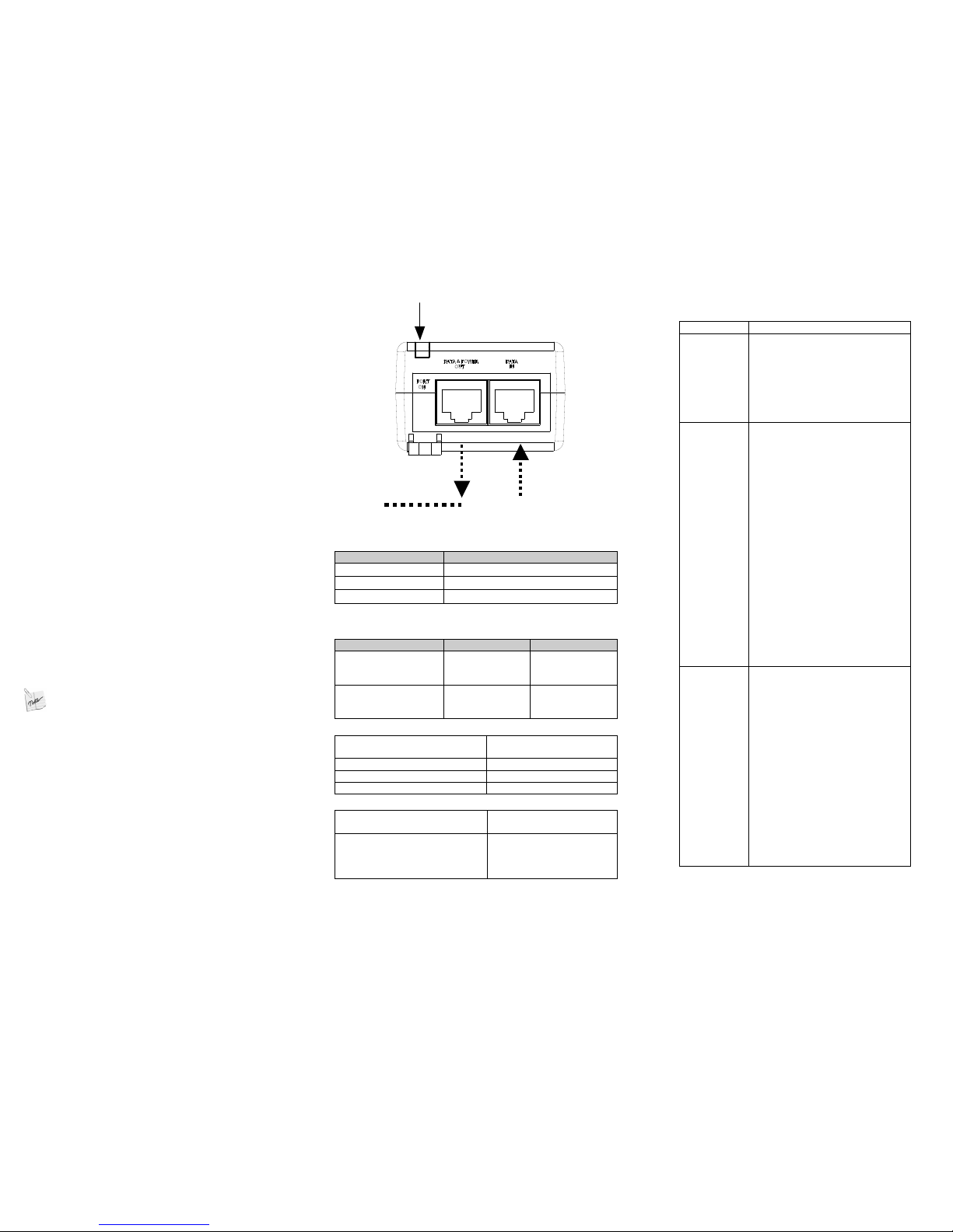
Port Connectivity
Indication
Ethernet
Cat .5 Cable
Terminal
Figure 1: Connecting the PD-3501G-ET
Indicators
Port LED
Indicated Behavior
Yellow On
Power is on (power is active)
Green On A remote terminal is connected
Green Blinking
Overload state or short-circuit
Specifications
Environmental Specifications
Mode
Temperature
Humidity
Operating -20 to 55°C
-4 to 131°F
10 to 90%; (no
condensation
allowed)
Storage
-20 to 85°C
-4 to 185°F
10 to 90%; (no
condensation
allowed)
Electrical Specifications
Input Voltage
100-240 VAC (50/60Hz)
Maximal Input Current
0.5 Ampere
Available Output Power (max.)
15.4 Watts
Nominal Output Voltage
50VDC
Ethernet Interface
Input (DAT A IN)
: Ethernet
10/100/1000Base-T
RJ45 female socket
Output (DAT A & POWER
OUT): Ethernet
10/100/1000Base-T, plus
50VDC
RJ45 female socket, with
DC voltage on wire pairs,
4-5 (+) & 7-8 (-).
3BFunctions and Features
PD-3501G-ET Power over Ethernet (PoE) is a Single Port
Midspan that offers a compact and cost effective power solution
for IP phones, WLAN access points, network cameras and other
IP terminal installations.
PD-3501G-ET converts AC power to 50VDC power that is then
provided over the Ethernet cable.
PD-3501G-ET supports up to
10/100/1000Mbps pass through data rates.
Extended Operating and Storage Temperature:
♦ Operating temp - -20C to +55C
♦ Storage temp - -20C to +85C
Single port PD-3501G-ET can be powered via universal
AC input and can provide up to 15.4W.
PD-3501G-ET EMC Compliance:
♦ FCC Part 15 class B and EN55022 class B
♦ EN55024
♦ VCCI
PD-3501G-ET Safety Compliance:
♦ UL/cUL per 60950-1
♦ GS Mark
4BPreliminary Step s
♦ Ensure AC power is applied to PD-3501G-ET using an
operational AC cable with an appropriate ground
connection.
♦ Ensure output Ethernet cable is connected to DATA &
POWER OUT port.
♦ Verify PoE Ready Ethernet compatible device is
connected.
5BWARNING:
Do not use cross over cable between PD-3501G-ET output
port and load device
6BInstallation
PD-3501G-ET can be placed on a desktop.
: Before placing PD-3501G-ET:
♦ Do not cover PD-3501G-ET or block airflow to PoE with
any foreign objects. Keep PD-3501G-ET away from
excessive heat and humidity and free from vibration and
dust.
♦ Ensure cable length from Ethernet network source to
terminal does not exceed 100 meters (330 feet). PoE is
not a repeater and does not amplify Ethernet
data signal.
♦ Use a splitter if desired; ensure splitter is connected
close to the terminal and not on PD-3501G-ET!
♦ No “on-off” switch exists; simply plug PD-3501G-ET into
an AC power source.
7BInstalling t he Unit
Refer to Figure 1.
1. Connect PD-3501G-ET to an AC outlet (100-240VAC) using a
standard power cord.
2. Connect DATA IN jack (input) to the remote Ethernet network
switch's Patch panel and DATA & POWER OUT jack (output) to
terminal.
 Loading...