

Page 1
MMiiccrroosseemmii PPooEE--EExxtteennddeerr UUsseerr GGuuiidde
e
MMiiccrroosseemmii PPooEE--EExxtteennddeer
r
Notice
It is Microsemi’s policy to improve its products as new
technology, components, software, and firmware
become available. Microsemi, therefore, reserves the
right to change specifications without prior notice.
Technical Support
If you encounter problems when installing or using this
product, please consult the Microsemi website at:
http://www.Microsemi.com.
For technical support, call: +972-9-775-5123
In the USA: 1-877-480-2323
Email: sales.support@microsemi.com
Recycling and Disposal
Disposal instructions for old products: The WEEE
(Waste Electrical and Electronic Equipment) national
environmental initiatives has been put in place to
ensure that products are recycled using best available
treatment, recovery and recycling techniques to ensure
human health and high environmental protection. Your
product is designed and manufactured with high quality
materials and components, which can be recycled and
reused. Do not dispose of your old product in your
general household waste bin. Inform yourself about the
local separate collection system for
electrical and electronic products
marked by this symbol:
Use one of the following disposal options :
1. Dispose of the complete product (including its cables,
plugs and accessories) in designated WEEE collection
facilities.
2. If you purchase a replacement product, hand your
complete old product back to the retailer. He should
accept it as required by national WEEE legislation.
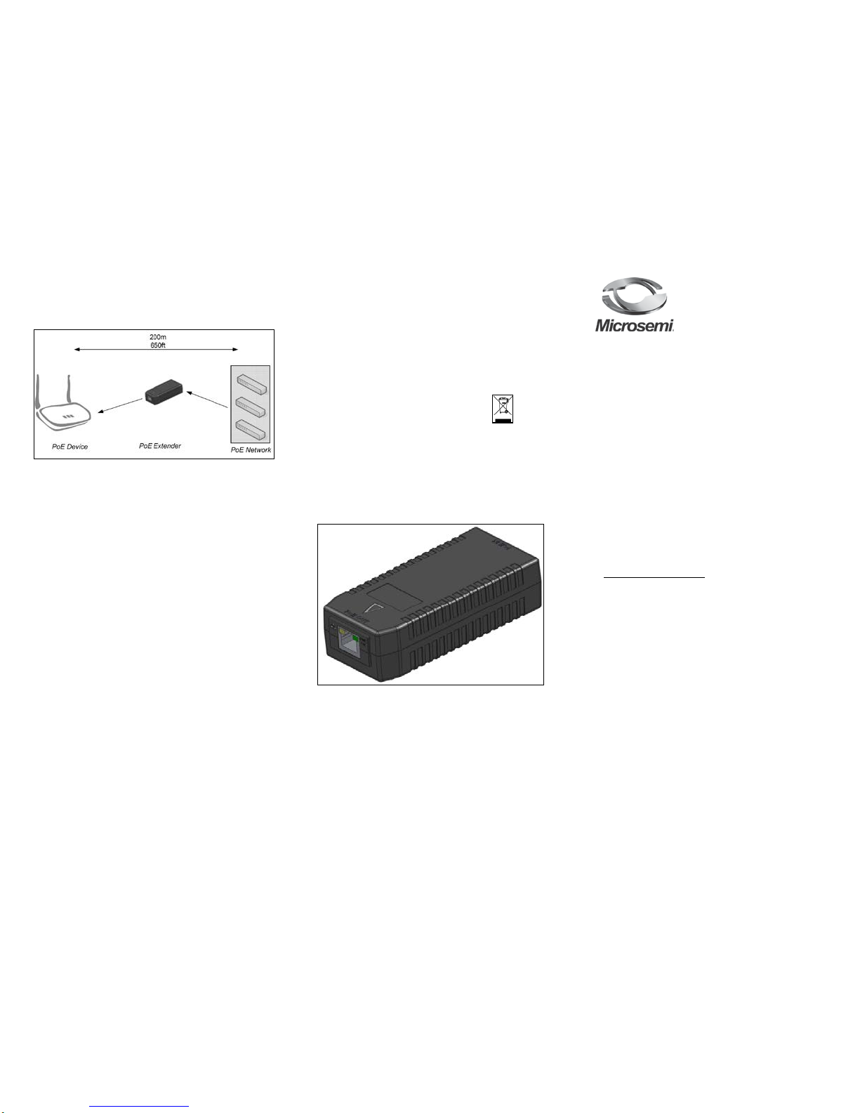
Figure 2: PoE Extender Unit
Microsemi Corp.
Covered under one or more of US Patents: #7,006,815; and
7,437,217.
Ordering information:
• Product Name: Microsemi PoE Extender
• Part Number: PD-PoE Extender
Document P/N 06-0039-056 Rev. B00
2B
Background
The PoE Extender can be used for installations that require
distances of more then 100 meters (328 feet) between the data
switch to the powered device.
Figure 1: Switch + Midspan -> 100 m -> PoE extender ->
100m -> WLAN AP
3BFunctions and Features
♦ Extends power and data range for up to 600 meters
with no need for an additional power source.
♦ Compatible with all Microsemi Midspans and
802.3af/802.3at PSEs.
♦ Can extend IEEE 802.3at PD range to 200 meters
when connected to Microsemi 95xx series (4-pair IEEE
802.3at)
♦ Supports 10/100/1000 mbps data rates
♦ Plug and Play; no configuration required during
installation.
4BPD-PoE Extender EMC Compliance:
♦ FCC Part 15 and EN55022
♦ EN55024
♦ VCCI
Page 2
Troubleshooting
Symptom
Corrective Steps
Extender
does not
power up
1. Verify that the input port of the
PoE extender is connected to an
active IEEE 803.af/at PSE
equipment.
The PD
does not
operate
1. Verify that the extender is
powered up.
2. Verify that the Extender detects a
PD.
3. Verify that the PD is designed for
IEEE 802.3 af/at operation.
4. Verify that you are using a
standard Category 5/5e/6, straightwired cable, with four pairs.
5. If an external power splitter is in
use, replace it with a known, good
splitter.
6. Verify that the PD is connected
to the Data & Power output port.
7. Try to reconnect the same PD
into a different Extender. If it works,
there is probably a faulty port or
RJ45 connection.
8. Verify that there is no short over
any of the twisted pair cables or
over the RJ45 connectors.
The end
device
operates,
but there
is no data
link
1. Verify that for this link, you are
using standard UTP/FTP Category
5/5e/6 straight (non-crossover)
cabling, with all four pairs.
2. Verify that the Ethernet cable
length is less than 100 meters from
the Ethernet source to the
load/remote terminal.
3. Try to reconnect the same PD
into a different Extender. If it works,
there is probably a faulty port or
RJ45 connection.
4. If an external power splitter is in
use, replace it with a known-good
splitter.
Indicators
Power LEDs
LED Color and
Status
PoE Input Status PoE Output Status
Green ON PoE input power
enabled
PoE output power
enabled
Green OFF PoE input power
disabled
PoE output power
disabled
Network LEDs
LED Color and
Status
Network Input/Output Status
Orange ON
Network connection
Orange OFF
No network connection
Orange Blinks –
12 Hz rate
10/100/1000 Mbps communication data
rate
Specifications
Environmental Specifications
Mode
Temperature
Humidity
Operating
1 G data rate
0 to 40°C
32 to 104°F
10 to 90%
(no condensation
allowed)
Operating
10/100 M data rate
0 to 50° C
32 to 122°F
10 to 90%
(no condensation
allowed)
Storage -20 to 70°C
-4 to 158°F
10 to 90%
(no condensation
allowed)
Electrical Specifications
Input Voltage 46 - 57 VDC
Maximal Input Current
0.7 Ampere
Output Voltage
44 - 55 VDC
Maximal Output Current
0.6 Ampere
Ethernet Interface
Input (Data & power In):
Ethernet 10/100/1000Base-T
RJ45 female socket
Output (Data & power In):
Ethernet 10/100/1000Base-T
RJ45 female socket
5BWARNING
♦ Read the installation instructions before connecting
the PoE Extender to the PSE.
♦ A voltage mismatch can cause equipment damage
and may pose a fire hazard. If the voltage indicated on the
label is different from the power outlet voltage, do not
connect the PoE Extender to the power outlet.
♦ The unit is indoor rated.
6BPreliminary Step s
♦ The PoE Extender can be placed on a rack, wall or
desktop.
Before placing the PoE Extender:
♦ Do not cover the PoE Extender. Keep the PoE Extender
away from excessive heat and humidity and free from
vibration.
♦ Use a splitter if desired; ensure that the splitter is
connected close to the PD terminal and not on the
Extender.
♦ No “on-off” switch exists; simply plug the Cat5e
Ethernet cable from the PSE device (PoE switch or
Midspan) to the Extender PoE input (RJ45 connector).
♦ Extender PoE output (the RJ45 connector) should be
connected to the PD terminal using a Cat5e Ethernet
cable.
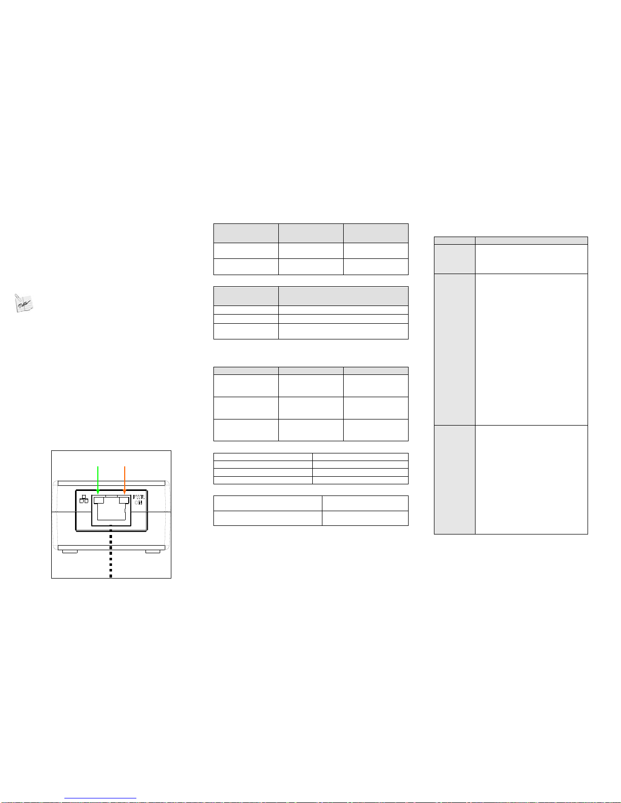
7BInstalling the Unit
1. Connect the PoE input port to a PSE (Midspan or Switch).
2. Connect the PoE output port to a PD (IP Phone, WLAN AP,
IP Camera, and so on).
3. Verify that the unit LEDs are on.
Power
LED
Network
LED
PoE + Data
Cat 5 Cable
Figure 3: Connecting the PoE Extender
 Loading...