

Page 1
Safety Information
Important Safety Information
♦ Install ation and removal of the PoE Midspan must be
carried out by qualified personnel only.
♦ The external power suppl y f or the equipment shall be a
Listed, Direct Plug In power unit, marked Cl ass 2, or
Listed ITE Power Supply, marked LPS, which has
suitably rated output voltage, and current.
♦ AC P ower inlet Set:
The power connector supplied with the PoE
Midspan has 2 terminals (See Figure 2) –
The polarity of the input connection is not
important.
The power inlet cables must be rated for
minimum current capacity of 6
Amperes (Stranded
Tinned Copper 12 AWG for each terminal or
2X16 AWG for each terminal).
Before connecting power inlet cables to the
connector terminals verify that the power source
is turned off.
After insertion of cable inlet to the connector
terminals tightly fasten all 4 connector screws
(See Figure 2).
This clause is optional:
Only for improved EMI performance, connect chassis
ground connection to "Earth/Ground" connection at
the working area.
: There is no safety hazard when the chassis ground
connection is not connected to the "Earth/Ground".
: The PoE injector "DATA IN" and " DATA & POWER OUT"
ports are shielded RJ45 data sockets. T hey cannot be
used as Plain Old Telephone Service (POTS) sockets. Only
RJ45 data connectors may be connected to these sockets.
The 24VAC power source mus t be near the PoE Midspan and
easily accessible. You can remove AC power from the PoE
Midspan by disconnectin g the 24VAC power inlet from ei ther the
24VAC power source or the PoE Midspan power connector.
The PoE Midspan "DATA IN" and "DATA & POWER OUT"
interfaces are qualified as SELV (Safety Extra-Low Voltage)
circuits according to IEC 60950-1. Thes e interfaces can only be
connected to SELV interfaces on other equipment.
WARNINGS!
• Read the installation instructions before connecting the PoE
Midspan to its power source.
• Follow basic electricit y safety measures whenever connecting
the PoE Midspan to its power source.
• A voltage mismatch can cause equipment damage and may
pose a fire hazard. If the voltage indicated on the label is
different from the power outlet voltage, do not co nnect the PoE
Midspan to this power outlet.
• Take extra attention when connecti ng the power inlet
terminals, so they will not touch chassis ground.
Mounting Instructions
Perform the following instructions:
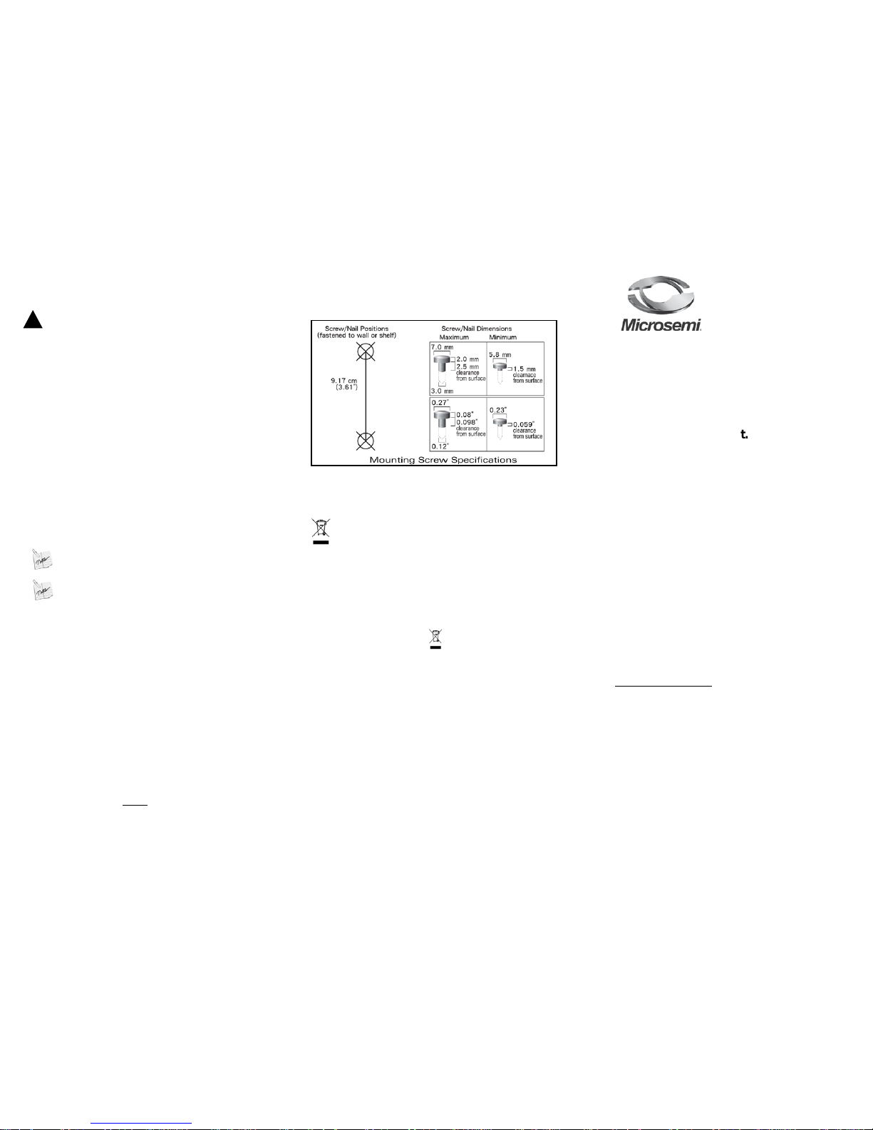
1. Install two screws in the wall or shelf as shown in Figure 1.
Figure 1: PoE Midspan mounting instructions
2. Align the PD-9501G/24AC mounting slots to capture the surface
screws
Recycling and Disposal
Disposal ins tructions for o ld products. The WEEE (Waste
Electrical and Electronic E quipment) national environmenta l
initiatives has been put in place to ensure that products are
recycled using best available treatment, recovery and
recycling techniques to ensure human health and high
environmental protection. Your product is designed and
manufactured with high quality materials and components,
which can be recycled and reused. Do not dispose of your
old product in your general household waste bin. Inform
yourself about the local separate collection system for
electrical and electronic products marked by this symbol:
Use one of the following disposal options :
1. Dispose of the complete product (including its cables,
plugs and accessories) in the de signated WEEE collection
facilities.
2. If you purchase a replacement product, hand your
complete old product back to the retailer. He should accept
it as required by the national WEEE legislation.
Microsemi Corp.
Ordering information:
• Product Name: Microsemi 9501G/24AC
• Part Number: PD-9501G/24AC
• Description: 1-Port 802.3at 4-Pairs Gigabit PoE Midspan
Document P/N PD9501G24AC_UG-EN Rev. B00
0BMicrosemi 9501G/24AC
1BUser Guide
2B1-Port 802.3at 4-Pairs Gigabit PoE
Midspan, 24VAC input.
Notice
It is Microsemi’s policy to improve its products as
new technology, components, software, and firmware
become available. Microsemi, therefore, reserves the
right to change specifications without prior notice.
Technical Support
If you encounter problems when installing or using this
product, please consult the Microsemi website at:
http://www.microsemi.com
For technical support, call: +972-9-775-5123
In the USA: 1-877-480-2323
Email: sales.support@microsemi.com
Page 2
Functions and Features
The High-Power Gigabit single port PoE (Power over Ethernet)
PD-9501G/24AC Midspan injects power over data-carrying Ethernet cabli ng. It
maintains the IEEE802.3at draft 3.2 and IEEE802.3 af standard, while doubling
the output power (60W). These power levels all ow usage by a new range of
Ethernet-based applications such as Video Phones, 802.11n Access Points,
WiMAX Transmitters, PTZ Cameras & more. The PD-9501G/24AC "DATA &
POWER OUT" port is designed to carry Gigabit Ethernet data & power over a
standard CAT5e cable, delivered through all 4-pairs
(Alt A: pins 1,2 (-) & 3,6 (+), Alt B: 4,5 (+) and 7,8 (-)).
EMC Compliance:
• FCC Part 15 class B
• EN55022 class B
• EN55024
Safety compliance:
• UL60950-1
• GS mark
Preliminary Steps
• Ensure 24VAC power is applied to t he PoE Midspan, using cables of 12
AWG for each terminal or 2X16 AWG for each terminal
(rated for 6
Amperes)
, with an appropriate separate ground connection (when
needed).
• Ensure output Ethernet cable is connected to the
"DATA & POWER OUT" port.
• Verify that power ready Ethernet compatible device is connected.
WARNING
Do not use cross over cable between the PoE Midspan output port
and the load device
Installation
The PoE Midspan may be located on a desktop or wall/bench mounted us i ng t he
rear side mounting holes.
• Associated Ethernet wiring shall be limited to inside of the building
• The power inlet cable and chassis connection cable is not supplied with the
product
: Before mounting the PoE Midspan to a fixed location:
• Do not to cover PoE Midspan or block the airflow to the PoE with any foreign
objects. Keep the PoE Midspan away from excessive heat a nd humidity and
free from vibration and dust.
• Ensure that the cable length from Ethernet network so urce to the terminal
does not exceed 100 meters (333 Feet). The PoE is no t a repeater and does
not amplify the Ethernet data signal.
• Use a splitter if desired; ensure that the splitter is connected close to the
terminal and not on the Midspan!
• No “on-off” switch exists; simply plug the PoE Midspan into a 24VAC power
source.
Installing the Unit
• V erif y the 24VAC power source is turned off.
• If the supplemental earth ground is replaced, apply 5Lb/In torque.
(Optional)
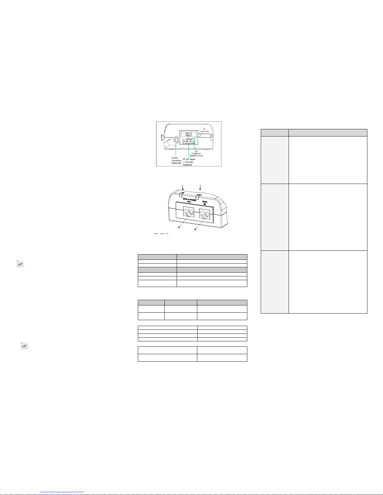
• Tighten the 2 connector screws (See Figure 2).
• Conn ect the PoE Midsp an In put co nnector to cables of Stranded Tinned
Copper, 12 AW G for each terminal or 2X16 AWG for each terminal
(rated for 6 Amperes) and tighten the 2 Cable inlet screws
(See Figure 2).
: The polarity of the inpu t co nn ection is not important.
• Connect the "DATA IN" jack (input) to the remote Ethernet network
switch's Patch panel and t he "DATA & POWER OUT" jack (output) to
the terminal (See Figure 3).
• Turn on the 24VAC power source and verify appropriate leds indication.
Figure 2: PoE Midspan Power Connector
Main LED
Indication
Port LED
Indication
Terminal
Ethernet
Port
Input
Port
Output
Cat 5. cable
13BFigure 3: PoE Midspan Ports
Indicators
Main LED Behavior
OFF Power OFF indication
Green on
Power ON indication (power is active)
Port LED Behavior
OFF
No detection or disconnected, no load is connected.
Green on
Power supplied over data and spare pairs
Blinking green at 1Hz rate
Port was powered at four pairs, then port was
overloaded / shorted
Specifications
18BEnvironmental Specifications
Mode Temperature Humidity
Operating
-10 to 40°C
14 to 104°F
10 to 90%
(no condensation allowed)
Storage
-20 to 70°C
-4 to 158°F
10 to 90%
(no condensation allowed)
16BElectrical Specifications
Input Voltage 22 – 28VAC (50-60Hz)
Input Current
6 ampere (max)
Available Output Power (max.) 60 Watts
Nominal Output Voltage
53.5 to 55.5VDC
19BEthernet Interface
Input (DATA IN):
Ethernet 10/100/1000Base-T
RJ45 female socket
Output (DATA & POWER OUT):
Ethernet 10/100/1000Base-T, plus 55VDC
RJ45 female socket, with DC voltage
on wire pairs 1-2, 3-6, 4-5 & 7-8.
17BTroubleshooting
Symptom Corrective Steps
PoE Midspan
does not
power up
1. Ensure that the
installation was
according to "Installing the Unit" section
in this user guide.
2. Ensure that the power source voltage is
between 22-28VAC and can carry out
80W.
3. Remove and re-apply power to the PoE
Midspan, and Verify that the main led
indicator on the front panel is
continuously lit.
The Powered
Device (PD)
does not
operate
1. Verify that the PD is designed for PoE
operation according to IEEE802.3af/at
standard.
2. Verify that you are using a standard
straight-wired four Pairs cable
(UTP/FTP Category 5/5e/6).
3. Verify that the PD is connected to the
PoE Midspan "DATA & POWER OUT"
port.
4. If an external power splitter is in use,
replace it with a known-good splitter.
5. Remove and re-apply power to the PoE
Midspan, and check the led indicators
during power up sequence.
The end
device
operates, but
there is no
data link
1. Verify that the port led indicator on the
front panel is continuously lit.
2. Verify that you are using a standard
straight-wired four Pairs cable
(UTP/FTP Category 5/5e/6).
3. Verify that the Ethernet cable length is
less than 100 meters from Ethernet
source to load/remote terminal.
4. Ensure that the input Ethernet cable is
connected to the PoE Midspan "DATA
IN" port.
5. If an external power splitter is in use,
replace it with a known-good splitter.
 Loading...