

Page 1
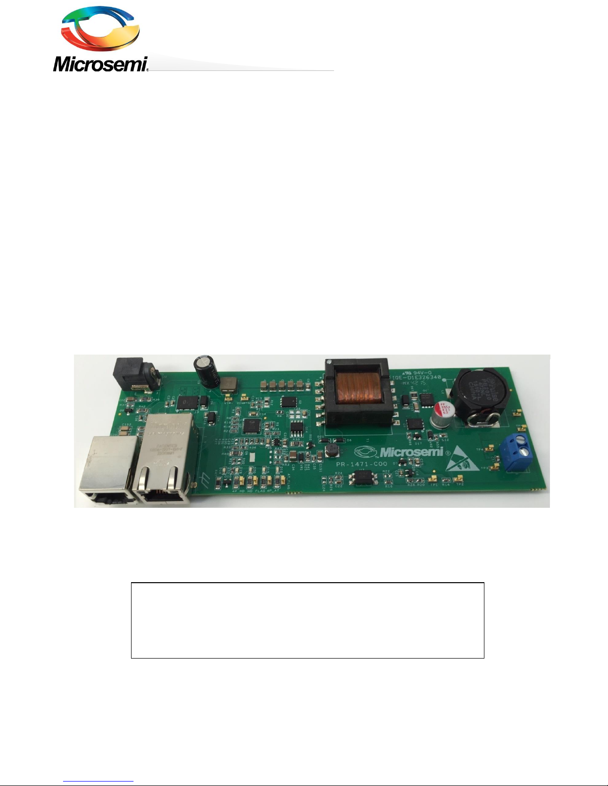
PD70211EVB50FW-5
50W Isolated Forward Converter PD
Evaluation Board
PD70211EVB50FW-5
5V/50W Isolated Active Clamp Forward Converter PD
Evaluation Board User Guide
Revision 2.0
PRODUCTION DATA – Information contained in this document is proprietary to
Microsemi and is current as of publication date. This document may not be
modified in any way without the express written consent of Microsemi. Product
processing does not necessarily include testing of all parameters. Microsemi
reserves the right to change the configuration and performance of the product and
to discontinue product at any time.
Page 2

Copyright © 2015 Microsemi Page 2 of 26
Rev. 2.0, 29-June-16 CPG – PoE BU
One Enterprise Aliso Viejo, CA 92656 USA
PD70211EVB50FW-5
50W Isolated Forward Converter PD
Evaluation Board
1 About this Guide
This user guide provides both description and operation procedures for Microsemi's PD70211EVB50FW evaluating
board. This board is used for evaluating the performance of PD70211A PD controller with integrated switching
regulator, and PD70224 Dual MOSFET – Based Bridge Rectifier.
PD70211ILQ device supports both the standard IEEE802.3at PD application interface, and a PWM controller that is
used to provide the PD operational voltage.
The evaluation board supports a 50 Watt, 5V output in its existing configuration, with no heat sink, at room
temperature.
1.1 Audience
This user guide is intended for qualified personnel, meaning operators and technicians who have a background in
basic concepts of electronics.
1.2 Organization
This guide is divided into several sections as follows:
Chapter 1
About this Guide: Describes the objectives, audience, and organization.
Chapter 2
Introduction: Provides an overview about evaluation board’s main functions,
features, physical characteristics and ordering information.
Chapter 3
Physical Description: Provides explanation related to the physical
description (switches, jumpers, connectors).
Chapter 4
Electrical Characteristics: Provides electrical characteristics of the
evaluation board.
Chapter 5
Installation: Provides description of the installation process.
Chapter 6
Test Data: Provides board test data information
Chapter 7
Schematic: Provides board schematic diagram
Chapter 8
List of Material: Provides board’s list of materials.
Chapter 9
Board Layout: Provides board Gerber files description for all layers..
1.3 Reference Documents
PD70211 datasheet, catalogue number DS_PD70211
PD70224 datasheet, catalogue number DS_PD70224
Page 3
Copyright © 2015 Microsemi Page 3 of 26
Rev. 2.0, 29-June-16 CPG – PoE BU
One Enterprise Aliso Viejo, CA 92656 USA
PD70211EVB50FW-5
50W Isolated Forward Converter PD
Evaluation Board
2 Introduction
Microsemi’s PD70211ILQ device is part of a family of devices which are targeted for realizing the 802.3at standard
PD interface.
The PD interface family of devices includes the following:
Device type
Power capability
Integrates PWM
controller
PD70100
IEEE802.3at Type 1
(IEEE802.3 af level)
No
PD70101
IEEE802.3at Type 1
(IEEE802.3 af level)
Yes
PD70200
IEEE802.3at Type 2
No
PD70201
IEEE802.3at Type 2
Yes
PD70210(A)
2 x IEEE802.3at Type 2 (4 pair)
HDBaseT (95W)
No
PD70211
2 x IEEE802.3at Type 2 (4 pair)
HDBaseT (95W)
Yes
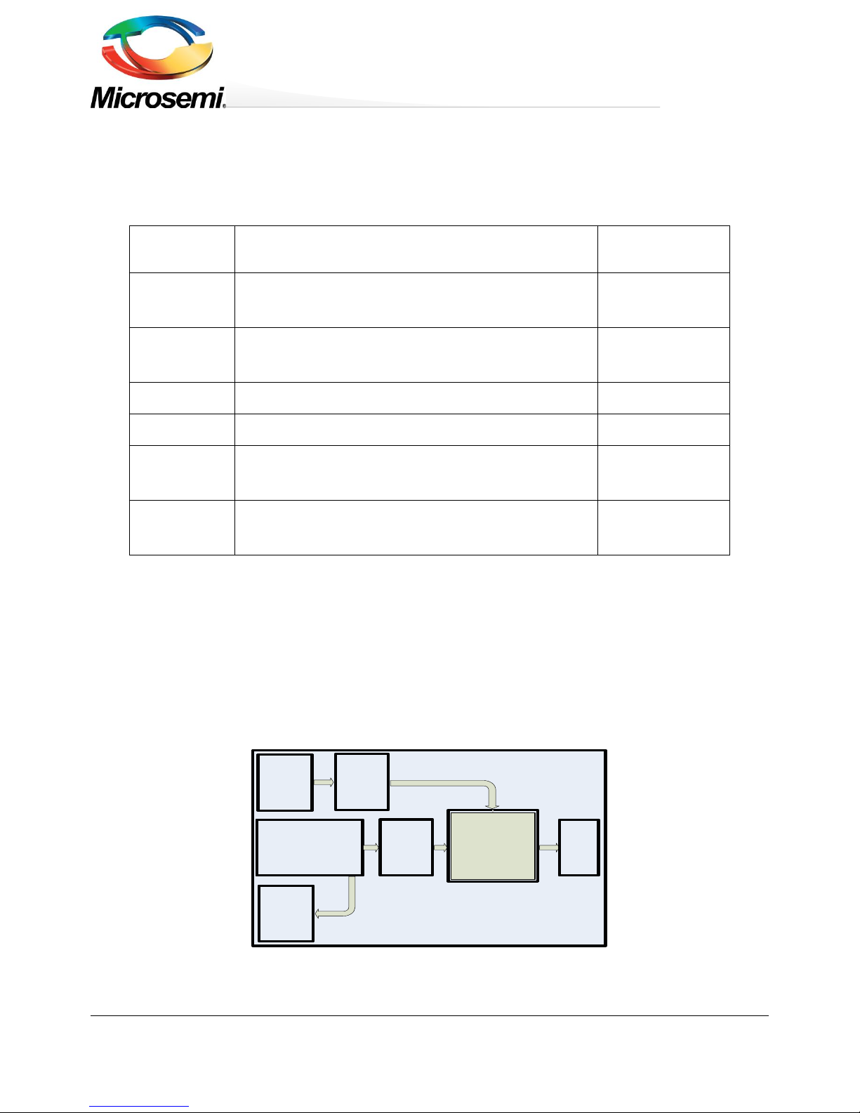
Microsemi’s PD70211EVB50FW Evaluation Board (see
Figure 2) provides designers with an environment needed for evaluating the performance and implementation of
PD applications based on PD70211 controller.
The board is using a single PD controller, PD70211ILQ, to support the Detection, Class, and Power Supplying
phases on the 4 Pairs of the Cat5 cable. The board supports sync detection of the 4 pairs. PD70211ILQ supports
the current of the HDBaseT over 4 Pairs, which is more than twice the power of a standard IEEE802.3AT Type 2
interface.
All necessary steps and connection instructions required to install and operate this board are provided within this
document.
PD70211 Based
Vin to 24V
Flyback DCDC
Module
RJ45 Data +
Power
Combined RJ45 &
Pulse Transformer
Vout
Conn
PD70224
Active
Mosfet
Bridges
Vin
Combined
Vin
5V
PD70211 Based
Vin to 5V
Forward DCDC
Module
48V Wall
Adapter
Wall
Adapter
Detection
Data
Output
Figure 1: PD70211EVB50FW-5 Block Diagram
Page 4
Copyright © 2015 Microsemi Page 4 of 26
Rev. 2.0, 29-June-16 CPG – PoE BU
One Enterprise Aliso Viejo, CA 92656 USA
PD70211EVB50FW-5
50W Isolated Forward Converter PD
Evaluation Board
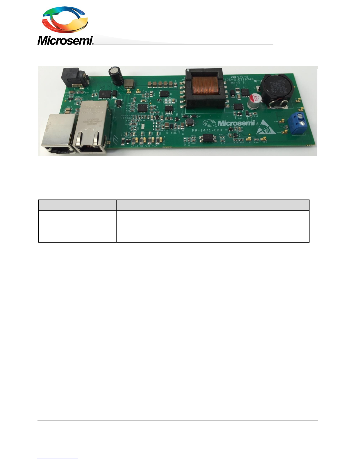
Figure 2: PD70211EVB50FW Evaluation Board – General View
Evaluation Boards Ordering Information
Microsemi supplies the following Evaluation Board as shown below:
Ordering Number
Description
PD70211EVB50FW-5
2 x IEEE802.3at Type 2 (4 pair) PD based on PD70211 device having 4 pair
supply, controlling an isolated Forward converter, having a 5V 10 Amp
output.
Page 5

Copyright © 2015 Microsemi Page 5 of 26
Rev. 2.0, 29-June-16 CPG – PoE BU
One Enterprise Aliso Viejo, CA 92656 USA
PD70211EVB50FW-5
50W Isolated Forward Converter PD
Evaluation Board
2.1 Evaluation Board Features
Designed to support Data and Spare current by a single PD70211A device
Power is supplied through the 4-pairs of the Cat5 cable
Wall Adapter input – Standard Barrel Jack available for connecting to an external 48V Wall
Adapter.
Data pass-through connector
On board PSE class type LED indicators
On board AT detected LED indicator
On board 4P_AT detected LED indicator
On board HD detected LED indicator
On board 4P_HD detected LED indicator
On board Power Good LED indicator which may be configured to monitor PD Front End or
VPP UVLO.
Ta: 0° to +70°C (with derating curve)
RoHS compliant
2.2 Physical Characteristics
Table 1 lists evaluation board’s physical characteristics.
Table 1: Physical Characteristics
Parameter
Value
Mechanical dimensions in mm
165 x 57 x 16 mm (L x W x H)
Page 6

Copyright © 2015 Microsemi Page 6 of 26
Rev. 2.0, 29-June-16 CPG – PoE BU
One Enterprise Aliso Viejo, CA 92656 USA
PD70211EVB50FW-5
50W Isolated Forward Converter PD
Evaluation Board
3 Physical Description
3.1 Package Contents
Upon opening the Evaluation Board package, verify the following part is included.
If it seems damaged, contact local representative or Microsemi's headquarters.
Package content for standard shipments is:
PD70211EVB50FW Evaluation Board.
Wall Adapter Input Cable
3.2 Connectors
The following sections provide both general and detailed information regarding unit’s connectors.
3.2.1 Connectors Table
Table 2 lists the Evaluation Board's connectors.
Table 2: Connectors List
#
Connector
Name
Description
1
J1
RJ45 Connector
RJ45 port for Data + Power In for PSE connection
2
J2
Wall Adapter Input
Standard Barrel Jack used for 48V Wall Adapter. Wall
adapter connection will be automatically sensed and will
override the PSE power connected to J1.
3
J3, TP6 (-)
and TP5 (+)
Converter Output
Terminal pins for connecting a load to 5V output. J3
provides screw terminals for easy connection; TP5 and
TP6 provide solder pads for soldered connection.
4
J4
RJ45 Connector
RJ45 port for Data pass – through output
5
VIN+,
VINRTN
Converter Input
Monitor
Converter Input Rail Monitor – Used as a monitor for
DC-DC primary rail voltage.
6
TP1 and TP2
Frequency Analyzer
Connection
Used to connect to an external frequency response
analyzer for measuring loop stability.
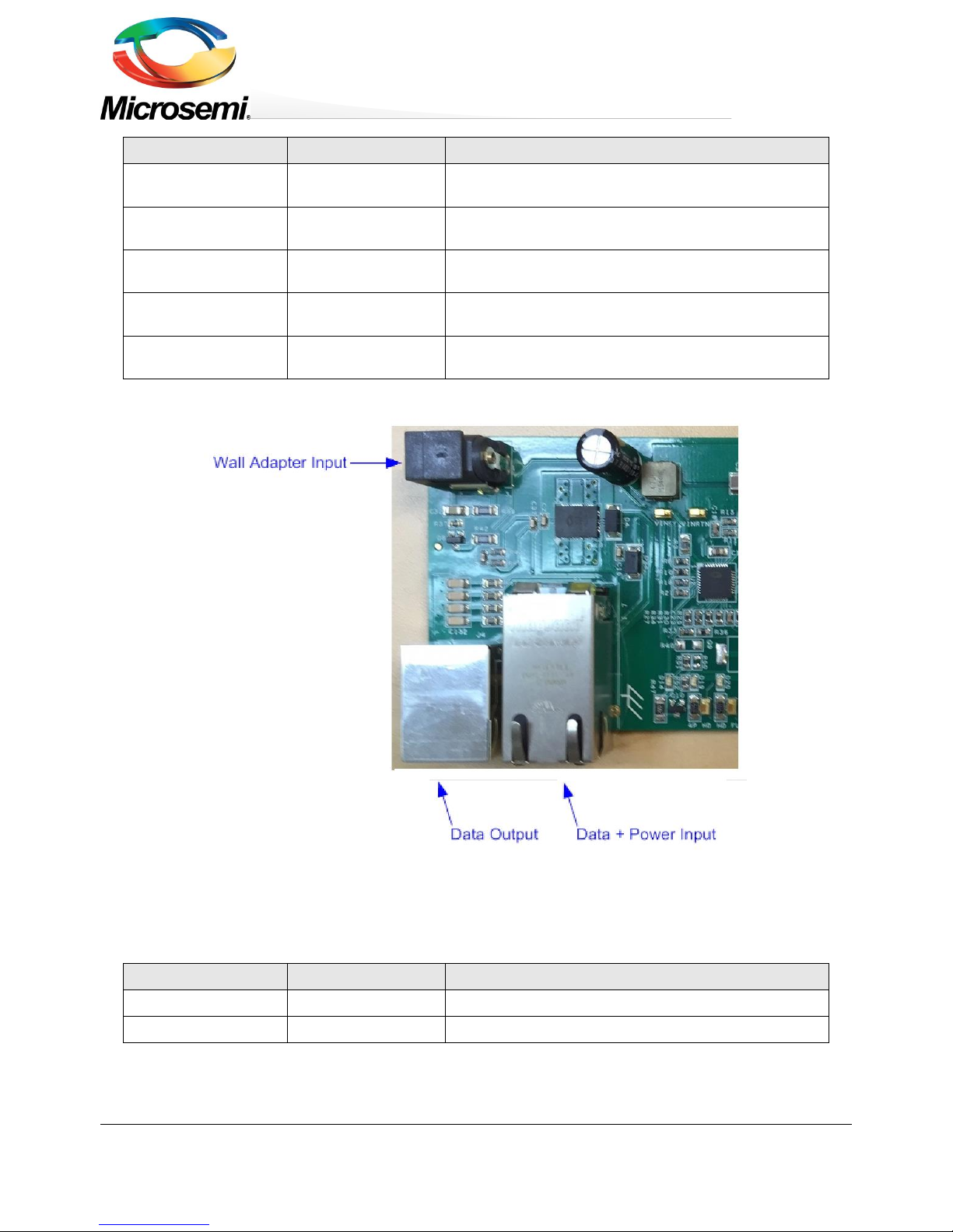
3.2.2 Connectors Detailed Explanation
(The numbering is in reference to the numbers listed in Table 2.)
1. RJ45 Connectors.
See Figure 3.
Table 3: RJ45 Connectors
J1 & J4 Pin No
Signal Name
Description
J1 - 1, 2
Data and Power In
Data and power input to powered device (PoE Master
Negative data port)
J1 - 3, 6
Data and Power In
Data and power input to powered device (PoE Master
Positive data port)
J1 - 4, 5
Data and Power In
Data and power input to powered device (PoE Master
Positive data port)
Page 7
Copyright © 2015 Microsemi Page 7 of 26
Rev. 2.0, 29-June-16 CPG – PoE BU
One Enterprise Aliso Viejo, CA 92656 USA
PD70211EVB50FW-5
50W Isolated Forward Converter PD
Evaluation Board
J1 & J4 Pin No
Signal Name
Description
J1 - 7, 8
Data and Power In
Data and power input to powered device (PoE Master
Negative data port)
J4 - 1, 2
Data Output
Isolated data pass-through to external monitoring
device.
J4 - 3, 6
Data Output
Isolated data pass-through to external monitoring
device.
J4 - 4, 5
Data Output
Isolated data pass-through to external monitoring
device.
J4 - 7, 8
Data Output
Isolated data pass-through to external monitoring
device.
Figure 3: Front RJ45 and Auxiliary 48V Wall Adapter Connectors
2. Wall Adapter Connections
See Figure 3.
J2 Pin No
Signal Name
Description
Center Pin
VIN (+)
42V to 57V input from wall adapter.
Outer Barrel
VIN (-)
Wall Adapter Return
Page 8
Copyright © 2015 Microsemi Page 8 of 26
Rev. 2.0, 29-June-16 CPG – PoE BU
One Enterprise Aliso Viejo, CA 92656 USA
PD70211EVB50FW-5
50W Isolated Forward Converter PD
Evaluation Board
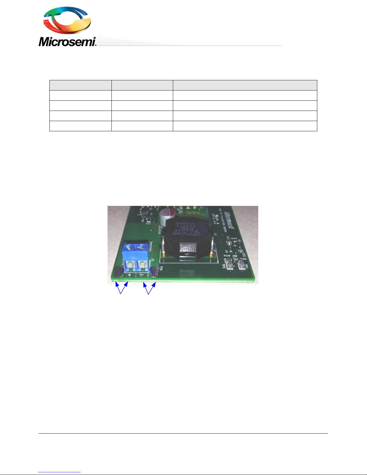
3. V
out
Connections
See Figure 4.
Table 4: Output Load Connections
Pin No.
Signal Name
Description
J3 - 2
Vout (-)
Return of DCDC output voltage
J3 - 1
Vout (+)
Positive DCDC output voltage
TP6
Vout (-)
Return of DCDC output voltage
TP5
Vout (+)
Positive DCDC output voltage
Vout (+)
Vout (-)
Figure 4: V
out
Connections
Page 9

Copyright © 2015 Microsemi Page 9 of 26
Rev. 2.0, 29-June-16 CPG – PoE BU
One Enterprise Aliso Viejo, CA 92656 USA
PD70211EVB50FW-5
50W Isolated Forward Converter PD
Evaluation Board
3.3 Indications
The following sections provide general information regarding unit’s indications.
1. LED Indication
See Figure 5.
3.3.1.1 LED Indication
See Figure 5.
D16 is the AT_FLAG indication LED, a PD70211 device output signal indicating the device has detected a 2 finger
class event from the PSE side in the class stage. The flag will be operative at 3, 4, and 6 fingers detection as well.
D15 is the 4P_AT indication LED, a PD70211 device output signal indicating the device has detected a 4 finger
class event from the PSE side in the class stage, or a 2 finger class event from the PSE side in the class stage,
and SUPP_Sa and SUPP_Sb are both High.
The flag will be operative at 6 fingers detection as well.
D20 is the HD_FLAG indication LED, a PD70211 device output signal indicating the device has detected a 3 finger
class event from the PSE side in the class stage.
The flag will be operative at 6 fingers detection as well.
D19 is the 4P_HD indication LED, a PD70211 device output signal indicating the device has detected a 6 finger
class event from the PSE side in the class stage.
D14 is the Power Good indication. This LED indicates the presence of power. This indicator may be configured to
monitor PD Front End VAUX (Asserts when VPP = 36V min.; de-asserts when VPP = 31V min.), or it may be
configured to monitor the VPP UVLO, which is user selectable by the resistor values at VINS and HYST pins (R13,
R19, and R25). See the PD70211 datasheet for further details regarding setting VPP UVLO limits. EVB default for
Power Good EVB is monitoring VPP UVLO, and will track the operation of the DC-DC converter. To change Power
Good to monitor PD Front End VAUX:
1) Remove R51, 100 Ohm Resistor (located on PCB bottom under D10).
2) Add R50 Zero Ohm Jumper (Also located on PCB bottom under D10).
3) Insure that only R51 or R50 are installed; do not operate with both resistors installed.
Figure 5: LED Indications
Page 10

Copyright © 2015 Microsemi Page 10 of 26
Rev. 2.0, 29-June-16 CPG – PoE BU
One Enterprise Aliso Viejo, CA 92656 USA
PD70211EVB50FW-5
50W Isolated Forward Converter PD
Evaluation Board
4 Electrical Characteristics
Evaluation board’s electrical characteristics are described below:
Table 5: Electrical Characteristics
Parameter
Min
Max
Main DC
Supply –
J1, VIN+,
VINRTN
42*
57
V
Wall
Adapter
Supply –
J2, VIN+,
VINRTN
42
57
V
Maximum
Available
Current
10
A
Port
Isolation to
Chassis
-
1.5
kVrms
*After start-up, the minimum voltage is 37V with load ≤ 13W per IEEE specification.
Page 11

Copyright © 2015 Microsemi Page 11 of 26
Rev. 2.0, 29-June-16 CPG – PoE BU
One Enterprise Aliso Viejo, CA 92656 USA
PD70211EVB50FW-5
50W Isolated Forward Converter PD
Evaluation Board
5 Installation
5.1 Preliminary Considerations and Safety Precautions
If using an external supply in place of a PSE, verify the external power supply is turned “off”
before all peripheral devices are connected. Insure the external supply is connected to the
RJ45 input (J1) per Table 3.
5.2 Initial Configuration
Note: It is important to verify evaluation board is setup as shown in Figure 6 prior to starting any operation.
1. Connect load to evaluation board (J3 -1 (+) & J3 – 2 (-), or TP17 (+) & TP16 (-)).
2. Connect a Cat5 cable from PSE to Evaluation Board (J1), or a 48V Wall Adapter to Evaluation Board (J2).
Note: Wall Adapter will override power from PSE.
Electronic Load
Power
Cable
DC output
PSE or 42V to 57V
Power Supply
Power +
Data Input
Cat5 cable
48V Wall
Adapter
Data Output
Figure 6: Test Setup
Page 12

Copyright © 2015 Microsemi Page 12 of 26
Rev. 2.0, 29-June-16 CPG – PoE BU
One Enterprise Aliso Viejo, CA 92656 USA
PD70211EVB50FW-5
50W Isolated Forward Converter PD
Evaluation Board
6 Test Data
This chapter describes EVB test data under various loads and POE input voltage levels.
The efficiency is indicated up to 50W output power.
Efficiency is measured at the input to the PD70224. It does not contain the RJ45 Connector or Magnetics
6.1 50W Efficiency vs Input Voltage to the PD70224
Figure 7: Efficiency vs Input Voltage
80.0%
82.0%
84.0%
86.0%
88.0%
90.0%
92.0%
94.0%
96.0%
98.0%
100.0%
40 42 44 46 48 50 52 54 56 58 60
Efficiency
Input Voltage
50W Efficiency vs. Input Voltage
Page 13

Copyright © 2015 Microsemi Page 13 of 26
Rev. 2.0, 29-June-16 CPG – PoE BU
One Enterprise Aliso Viejo, CA 92656 USA
PD70211EVB50FW-5
50W Isolated Forward Converter PD
Evaluation Board
6.2 Efficiency vs. Load Current at 48V Input to the PD70224
Figure 8: Efficiency at 48V Input
6.3 Load Regulation
Figure 9: Load Regulation at 48V Input
0.0%
10.0%
20.0%
30.0%
40.0%
50.0%
60.0%
70.0%
80.0%
90.0%
100.0%
0 2 4 6 8 10 12
Efficiency
Output Current
Efficiency vs. Load
-2.00%
-1.50%
-1.00%
-0.50%
0.00%
0.50%
1.00%
1.50%
2.00%
0 2 4 6 8 10 12
Regulation
Output Current
Load Regulation
Page 14

Copyright © 2015 Microsemi Page 14 of 26
Rev. 2.0, 29-June-16 CPG – PoE BU
One Enterprise Aliso Viejo, CA 92656 USA
PD70211EVB50FW-5
50W Isolated Forward Converter PD
Evaluation Board
6.4 Output Ripple
Figure 10: Full Load Voltage Ripple and Noise at 42V Input
Page 15

Copyright © 2015 Microsemi Page 15 of 26
Rev. 2.0, 29-June-16 CPG – PoE BU
One Enterprise Aliso Viejo, CA 92656 USA
PD70211EVB50FW-5
50W Isolated Forward Converter PD
Evaluation Board
6.5 Bode Plots
Bandwidth:
4731 Hz
Phase Margin:
82°
Gain Margin:
-28 dB
Bandwidth:
4731 Hz
Phase Margin:
82°
-180
-135
-90
-45
0
45
90
135
180
-60
-40
-20
0
20
40
60
10 100 1000 10000 100000
Bode Plot VIN = 42V +25°C
Gain
Phase
-180
-135
-90
-45
0
45
90
135
180
-60
-40
-20
0
20
40
60
10 100 1000 10000 100000
Bode Plot VIN = 57V +25°C
Gain
Phase
Page 16

Copyright © 2015 Microsemi Page 16 of 26
Rev. 2.0, 29-June-16 CPG – PoE BU
One Enterprise Aliso Viejo, CA 92656 USA
PD70211EVB50FW-5
50W Isolated Forward Converter PD
Evaluation Board
Gain Margin:
-28 dB
6.6 Step Load Response
Figure 11: Load Step Response
Load Current
2A/Div
Output
Voltage
Page 17

Copyright © 2015 Microsemi Page 17 of 26
Rev. 2.0, 29-June-16 CPG – PoE BU
One Enterprise Aliso Viejo, CA 92656 USA
PD70211EVB50FW-5
50W Isolated Forward Converter PD
Evaluation Board
7 Schematic
Figure 12: Evaluation Board Schematic (1 of 2)
Data4
Data5
Data7
Data2
Data3
Data6
Data1
DATA OUT
R60
75
PD-0805
PD-0805-W
R61 75
R62 75
R63 75
Term4
Term2
Term1
Term2
Term1
Term3
Term4
Term3
Power_Spare+
Power_Data+
Power_Spare-
J1
08261X1TGH-F
RJ45-16P_TRANS_LED
Shield21
21
Shield22
22
Led1_C
17
Led1_A
18
TRD1+
11
TRCT1
12
TRD1-
10
TRD2+
4
TRCT2
6
TRD2-
5
TRD3+
3
TRCT3
1
TRD3-
2
TRD4+
8
TRCT4
7
TRD4-
9
VC1
13
Led2_1
19
Led2_2
20
VC2
14
VC3
15
VC4
16
Power_Data-
POWER + DATA INPUT
U1
PD70224ILQ-TR.
OUTP_1
1
OUTP_2
2
OUTP_3
3
IN2B_5
5
IN2B_6
6
IN2B_7
7
IN2B_8
8
OUTN_10
10
OUTN_11
11
OUTN_12
12
IN2A_1313IN2A_1414SUPP_SA16SUPP_SB17IN1A_1919IN1A_20
20
OUTP_32
32
OUTP_31
31
OUTP_30
30
IN1B_28
28
IN1B_27
27
IN1B_26
26
IN1B_25
25
OUTN_23
23
OUTN_22
22
OUTN_21
21
EX_OUTP
41
IN2A_4040IN2A_3939IN1A_3434IN1A_33
33
EX_OUTN
42
NC_37
37
WA_EN
36
VPN_IN
12345678
J4
RJ45-I
1
1
2
2
3
3
4
4
5
5
6
6
7
7
8
8
9
9
10
10
D4
SMAJ58CA-13-F
PD-SMA
Power_Data+
Data3
Data4
Data1
Data2
Data6
Data7
Data8
Data5
D24
SMAJ58CA-13-F
PD-SMA
C27
1n 2000V
C152
1n 2000V
C39
1n 2000V
C153
1n 2000V
VIN+
VPN_IN
C37
10nf
C2
1nF
100V
X7R
PD-0603
C16
1nF
100V
X7R
PD-0603
SA
SB
C32
100n
100V
X7R
PD-1206
R37
2K
PD-0603
J2
RAPC712X
SWITCHCRAFT-RAPC722
2
3
1
VPN_IN
VIN+
WA_ENWA_EN_PD
D10
PD-SMB
B2100-13-F
2 1
Q8
ZVP3310FTA
PD-SOT23
2
1
3
D28
SMAJ58A
2 1
Q16 FDS86242
PD-SO8
4
3 8
7
6
5
2
1
R39
11K
0805
R90
4.02K
C165
10U
25V
X7R
R92
150K
R94
13K
R95
13K
R42
150K
WA_EN_R
C36
1uF
25V
X7R
PD-0805
WA_EN
Data8
Page 18

Copyright © 2015 Microsemi Page 18 of 26
Rev. 2.0, 29-June-16 CPG – PoE BU
One Enterprise Aliso Viejo, CA 92656 USA
PD70211EVB50FW-5
50W Isolated Forward Converter PD
Evaluation Board
Figure 13: Evaluation Board Schematic (2 of 2)
C11
22uF
10V
X5R
C24
PD-0603
N.C
SG
Vaux
GD1
TP5
1
VAUX_VCC
L3
4.7MH[4700uH}
IND-D5-SMD
1 2
TP6
1
+ C9
47uF
100
ALU
D8H15F3_5
VAUX_VCC
4P_AT_FLAG
C14
100n
16V
AT_FLAG
Q10
BSS123
PD-SOT23
2
1
3
VIN+
U4
TLVH432AIDBZR
PD-SOT23
13
2
R52
100K
PD-0603
R51
100
PD-0603
HYST
VAUX_VCC
C17
100n
100V
X7R
U5
FAN3111CSX
PD-SOT23-5
VDD
1
VIN+3VIN-
4
GND
2
VOUT
5
C31
1uF
25V
X7R
PD-0805
C151
1u
25V
X7R
PD-1206
R67
2.2 PD -1210 C155
2200pF
50V
X7R
+ C10
820uF
6.3V
ALU
Vaux
GD2
R41
0
PD-0805
R9
0 PD -0603
L1
4.7uH
1 2
C40
1uF
25V
X7R
PD-0805
R12
0.039mOhm
PD-1206
1
VPN_IN
C25
1uF
16V
X7R
R29
100K
PD-0603
5v0
D7
BAT54SLT1G
PD-SOT23
132
VR1
MMSZ4702
PD-SOD123
2 1
VIN+
C23
50V
47n
X7Rpd-0603
VL
C19
10V1u
VL
1
1
1
R27
100K
PD-0603
R69
40.2
PD-1206
C156
56pF
100V
NPO
pd-0805
pd-0805-w
HD_FLAG
4P_AT_FLAG
AT_FLAG
4P_HD_FLAG
R24
1.2K
PD-0603
CSN
CSP
R7 0
HYST
R13 0
PD-0805
R3
24.9K
PD-0805
R18
60.4K
PD-0603
R21
30.9
pd-0603
1
R30 43.2KPD-0603
R33
562K
pd-0603
R36
18.7K
PD-0603
R34
562K
pd-0603
VIN+
R20
14.7K
PD-0603
C33
0.1uF
25V
X7R
PD-0603
R28
4.87kOhms
PD-0603
C12
100nF
50V
VL
Q2
FDMS86252
PD-POWER_56
4
3 8
765
2
1
9
Q3
FDMS7698
PD-POWER_56
S1
1
S2
2
S3
3
GATE
4
D1
8
D2
7
D3
6
D4
5
HS
9
C21
22n
25V
X7R
PD-0603
U3
FOD817ASD
PD-SMD-4
1234
R23
20K
PD-0603
R19
20K
PD-0603
C20
1n2000V
Q1
BSC0902NSI
PD-TDSON8
S1
1
S2
2
S3
3
GATE
4
D1
8
D2
7
D3
6
D4
5
HS
9
R31 100KPD-0603
R25 0PD-0603
U2
PD70211ILQ-TR.
PD-QFN36-6X6
SUPP_S1
1
SUPP_S2
2
4P_AT_FLAG
3
RREF
4
RCLASS
5
HD_FLAG
6
AT_FLAG
7
VPN_IN8
8
VPN_IN9
9
VPN_OUT1010VPN_OUT1111ENABLE12VINS13HYST14SYNC15RFREQ16SS17RCLP
18
PGND
27
SG
26
VL
25
GND
24
FB
23
DAO
22
COMP
21
VSP
20
VSN
19
RDET
36
VPP
35
4P_HD_FLAG
34
WA_EN
33
VCC/VAUX
32VH31PG30
CSP
29
CSN
28
Trm_P
37
C7
2.2uF
100V
X7R
PD-1210
C5
2.2uF
100V
X7R
PD-1210
C6
2.2uF
100V
X7R
PD-1210
L2
4.7uH
COIL-24X21
2
1
SG
C8
100n
X7R
PD-0805
C3
2.2uF
100V
X7R
PD-1210
R68
0
PD-0603
Vaux
C4
2.2uF
100V
X7R
PD-1210
D25
MBR0540T1G
PD-SOD123
N.C
21
CSP
PG
R11
100
PD-0603
VR3
PD-SOD123
2 1
C154
10pF
50V
NPO
PD-0805
R64
1K
PD-0805
CSN
GD1
FREEWHL_DR AIN
R65
10K
PD-0805
C28
22n
200V
X7R
PD-0805
GD2
FW_DRAIN
C18
1nF
16V
X7R
PD-0603
R55
100K
PD-0603
VR2
MMSZ4705T1G
PD-SOD123
2 1
D17
MMBD4148
PD-SOT23
1 3
2
R66
10
PD-0603
Q15
MMBT2222A_NL
PD-SOT23
1
2 3
D22
MMBD4148
PD-SOT23
1 3
2
R15 100
PD-0603
R4
22.1
PD-0603
DRAIN
D1
SMAJ40A
PD-SMA
21
R38
1K
PD-1206
R26
0 PD-0603
D2
ES1C-13-F
2 1
R8 10K
R10 10K
FREEWHL_DR AIN
C34
22uF
25V
X7R
PD-1210
Q14
IRF6216TRPBF
PD-SO8
SA
SB
D6
1N4148W-7-F
PD-SOD123
PD-SOD123-w
21
D21
1N4148W-7-F
PD-SOD123
2 1
VPN_IN
FW_DRAIN
4P_HD_FLAG
VIN+
HD_FLAG
R16
510Ohms
PD-0603
C22
4.7NF
16V
X7R
PD-0603
D23
SMAJ20CA-13-F
PD-SMA
R47
30.1K
PD-1206
PD-1206-W
VISUAL (LED) STATUS INDICATION
WA_EN_PD
R14 20
PD-0603
D16
SSC-GR101
Super Green
EVERLIGHT-19-21YGC
21
D14
SSC-GR101
Super Green
EVERLIGHT-19-21YGC
21
D15
SSC-GR101
Super Green
EVERLIGHT-19-21YGC
21
D20
SSC-GR101
Super Green
EVERLIGHT-19-21YGC
21
D19
SSC-GR101
Super Green
EVERLIGHT-19-21YGC
21
TP3
1
TP2
1
5v0
TP1
1
GND-F
4P_HD
1
HD_FLAG
1
DRAIN
4P_AT
1
AT_FLAG
1
VINRTN
1
T1
N/A
EFD25-12-PIN-SMD
1
5
2
3
7
8
4
6
9
10
11
12
R49
5.11K
PD-1206
R58
5.11K
PD-1206
R48
5.11K
PD-1206
Vaux
R57
5.11K
PD-1206
C29
PD-0805
200V
X7R
22n
C30
PD-0805
200V
X7R
22n
J3
1
1
2
2
VIN+
1
C35
100nF
50V
X7R
PD-0603
TP4
1
R22
PD-0603
N.C
D12
BAV99W
2 1
3
R50
PD-0603
N.C
Page 19

Copyright © 2015 Microsemi Page 19 of 26
Rev.2.0, 29-June-16 CPG – PoE BU
One Enterprise, Aliso Viejo, CA 92656, USA
PD70211EVB50FW-5
50W Isolated Forward Converter PD
Evaluation Board
8 List of Materials
Qty
Ref Des
Part Value
Description
Mfr. Name
Mfr. Part Number
2
C2,C16
1nF
CAP CRM 100nF 100V 10%^^X7R 603
SMT
Any
Any
5
C3,C4,
C5,C6, C7
2.2uF
CAP CER 2.2UF 100V 10% X7R 1210
Taiyo Yuden
HMK325B7225KN-T
1
C8
100n
CAP CER 0.1UF 100V 10% X7R 0805
TDK
C2012X7R2A104K12
5AA
1
C9
47uF
CAP ALUM 47UF 100V 20% RADIAL
Nichicon
UPW2A470MPD
1
C10
820uF
CAP ALUM 820UF 6.3V 20% RADIAL
Nichicon
RL80J821MDN1KX
2
C11,C12
100n
Capacitor, Ceramic, 50V, X7R, 0603
Any
Any 2 C14,C40
100n
Capacitor, Ceramic, 10V, X7R, 0805
Any
Any
2
C17,C32
100nF
CAP CRM 100nF 100V 10%^^X7R
1206 SMT
Any
Any
1
C18
1nF
Capacitor, Ceramic, X7R, 16V, 0603
Any
Any 1 C19
1uF
Capacitor, Ceramic, 10V, X7R, 0805
Any
Any
5
C20,C27,
C39,
C152,
C153
1nF
CAP CRM 1nF/2000V 10% X7R 1206
SMT
AVX
1206GC102KAT1A
1
C21
0.1uF
Capacitor, X7R, 10V, 10% 0603
Any
Any
1
C22
4.7n
Capacitor, Ceramic, 10V, X7R, 0603
Any
Any 1 C23
47n
Capacitor, X7R, 25V, 10% 0603
Any
Any
1
C24
TBD
Capacitor, X7R, 10V, 10% 0603
Any
Any 1 C25
1uF
CAP CER 1UF 16V 10% X7R 0805
Any
Any
1
C28
22nF
CAP CER 0.022UF 200V 10% X7R 0805
Any
Any
1
C31
1uF
CAP CER 1UF 25V 10% X7R 0805
Any
Any
2
C33,C36
100n
Capacitor, Ceramic, 25V, X7R, 0603
Any
Any
1
C34
22u
Capacitor, Ceramic, 25V, X7R, 1210
Any
Any
1
C35
100n
CAP CER 0.1UF 100V 10% X7R 0603
Any
Any
2
C36,
C151
1u
CAP CRM 1uF 25V 10% X7R1206
Any
Any 1 C37
10nF
Capacitor, Ceramic, 100V 10% X7R
0603
Any
Any 1 C154
10pF
CAP CRM 10pF 50V 10% X7R 0805
SMT
Any
Any
1
C155
2200pF
Capacitor, Ceramic, 50V, X7R, 1206
Any
Any
Page 20

Copyright © 2015 Microsemi Page 20 of 26
Rev.2.0, 29-June-16 CPG – PoE BU
One Enterprise, Aliso Viejo, CA 92656, USA
PD70211EVB50FW-5
50W Isolated Forward Converter PD
Evaluation Board
Qty
Ref Des
Part Value
Description
Mfr. Name
Mfr. Part Number
1
C165
10uF
Capacitor, X7R, 10uF, 25V, 20% 1210
Murata
GRM32DR71E106MA
12L
1
D1
1SMAJ40A
TVS DIODE 40VWM 64.5VC SMA
Diodes Inc
SMAJ40A-13-F
1
D2
ES1C
DIO FAST SWI 150V, 1A
Fairchild
ES1C
2
D4,D24
1SMA58AT3G
TVS DIODE 58VWM 93.6VC SMA
Diodes Inc
SMAJ58CA-13-F
2
D6,D21
BAT41ZFILM
DIODE SCHOTTKY 100V 0.2A SOD123
STMicroelectr
onics
BAT41ZFILM
1
D7
BAT54SLT1G
DIODE SCHOTTKY 30V 200MA SOT23
On
Semiconducto
r
BAT54SLT1G
1
D10
B2100
DIODE SCHOTTKY 100V 2A SMB
Diodes Inc
B2100-13-F
3
D12,D17,
D22
MMBD4148
DIODE SML SIG 100V 0.2A SOT23-3
Fairchild
MMBD4148
1
D23
SMAJ20CA
TVS DIODE 20VWM 32.4VC SMA
Diodes Inc
SMAJ20CA-13-F
5
D14,D15,
D16,D19,
D20
LTSTC193KGKT5A
LED GREEN RECT CLEAR 0603
LITE-ON
LTST-C193KGKT-5A
1
J1
MagJack
CONN MAGJACK 1PORT 1000 BASE-T
Bel Stewart
8261X1TGH-F
1
J2
RAPC722X
DC Power Jack 16V 5A TH
Switchcraft
RAPC722X
1
J3
ED500/2DS
TERMINAL BLOCK 5MM 2POS PCB
On Shore
Technology
ED500/2DS
1
J4
3060115907
CON RJ45 SINGLE 8 POS. SHIELDED
Kinsun
3060115907
1
L1
4.7uH
FIXED IND 4.7UH 5.5A 40 MOHM SMD
Vishay
IHLP2525CZER4R7M
01
1
L2
4.7uH
FIXED IND 4.7UH 16.8A 4.5 MOHM
Pulse
PB2020.472NL
1
L3
4.7mH
FIXED IND 4.7MH 40MA 48 OHM SMD
Bourns
SDR0503-472JL
1
Q1
BSC0902NSI
MOSFET N-CH 30V 100A 8TDSON
Infineon
Technologies
BSC0902NSI
1
Q2
FDMS86252
MOSFET N-CH 150V 16A POWER 56
Fairchild
FDMC86252
1
Q3
FDMS7698
MOSFET N-CH 30V 13.5A POWER56
Fairchild
FDMS7698
1
Q8
ZVP3310FTA
MOSFET P-CH 100V 75MA SOT23-3
Diodes Inc
ZVP3310FTA
1
Q9
PZTA06
TRANSISTOR GP NPN 80V SOT-223
Fairchild
PZTA06
1
Q10
BSS123
MOSFET N-CH 100V 170MA SOT-23
Fairchild
BSS123
1
Q14
IRF6216
MOSFET P-CH 150V 2.2A 8-SOIC
International
Rectifier
IRF6216TRPBF
1
Q15
MMBT2222A
TRANS NPN 40V 0.6A SMD SOT23-3
Diodes Inc
MMBT2222A-7-F
Page 21

Copyright © 2015 Microsemi Page 21 of 26
Rev.2.0, 29-June-16 CPG – PoE BU
One Enterprise, Aliso Viejo, CA 92656, USA
PD70211EVB50FW-5
50W Isolated Forward Converter PD
Evaluation Board
Qty
Ref Des
Part Value
Description
Mfr. Name
Mfr. Part Number
1
Q16
FDS86242
N-CH POWER MOSFET 150v 4.1A SO8
Fairchild
FDS86242
1
R3
24.9K
Resistor, 1%, 1/10W, 0805
Any
Any 1 R4
2.7
Resistor, 5%, 1/10W, 0603
Any
Any
4
R7,R13,
R25,R26
0
Resistor, 5%, 1/10W, 0603
Any
Any
2
R8,R10
10K
Resistor, 1%, 1/16W, 0603
Any
Any
1
R9 0 Resistor, 1%, 1/16W, 0603
Any
Any
2
R11,R15
100
Resistor, 1%, 1/16W, 0603
Any
Any
1
R12
0.043
RES SMD 0.043 OHM 1% 1/2W 1206
TE
Connectivity
1-2176055-6
1
R14
20
Resistor, 5%, 1/10W, 0603
Any
Any
1
R16
510
Resistor, 5%, 1/10W, 0603
Any
Any
1
R18
60.4K
Resistor, 60.4K Ohms, 1/16 Watt, 1%
0603 Type SMD
Any
Any
2
R19,R23
20K
Resistor, 5%, 1/10W, 0603
Any
Any 1 R20
14.7K
Resistor, 1%, 1/16W, 0603
Any
Any
1
R21
30.9
Resistor, 30.9 Ohms, 1/16 Watt, 1%
0603 Type SMD
Any
Any
2
R22,R50
NC
Resistor, 5%, 1/10W, 0603
Any
Any
1
R24
1.2k
Resistor, 5%, 1/10W, 0603
Any
Any
6
R27,R29,
R31,R45,
R52,R55
100K
Resistor, 5%, 1/10W, 0603
Any
Any
1
R28
4.87K
Resistor, 1%, 1/16W, 0603
Any
Any
1
R30
43.2k
Resistor, 1%, 1/16W, 0603
Any
Any
1
R33
562K
Resistor, 1%, 1/10W, 0805
Any
Any
1
R34
562K
Resistor, 1%, 1/16W, 0603
Any
Any
1
R36
18.7K
Resistor, 1%, 1/16W, 0603
Any
Any
1
R37
2.00k
Resistor, 5%, 1/10W, 0603
Any
Any
1
R38
1K
Resistor, 1K Ohms, 1/4 Watt, 5% 1206
Type SMD
Any
Any
1
R39
11K
RES 11K 250 mW 1% 1206 SMT MTL
FLM
Any
Any
Page 22

Copyright © 2015 Microsemi Page 22 of 26
Rev.2.0, 29-June-16 CPG – PoE BU
One Enterprise, Aliso Viejo, CA 92656, USA
PD70211EVB50FW-5
50W Isolated Forward Converter PD
Evaluation Board
Qty
Ref Des
Part Value
Description
Mfr. Name
Mfr. Part Number
1
R40
2.2k
Resistor, 5%, 1/4W, 1206
Any
Any
1
R41 0 Resistor, 5%, 1/10W, 0805 SMD
Any
Any
2
R42, R92
150K
RES 150K 250 mW 1% 1206 SMT MTL
FLM
Any
Any
1
R43
1k
Resistor, 5%, 1/10W, 0603
Any
Any
1
R44
820
Resistor, 1%, 1/16W, 0603
Any
Any
1
R46
620
Resistor, 1%, 1/16W, 0603
Any
Any
1
R47
20K
RES TK FLM 20K 250mW 1%1206
Any
Any 2 R48,R57
5.6k
Resistor, 5%, 1/4W, 1206
Any
Any
2
R49,R58
5.6k
Resistor, 5%, 1/4W,1206
Any
Any
1
R51
100
Resistor, 5%, 1/10W, 0603
Any
Any
4
R60,R61,
R62,R63
75
Resistor, 1%, 1/10W, 0805
Any
Any
1
R42
15.0K
Resistor, 1%, 1/4W, 1206
Any
Any 1 R43
1k
Resistor, 5%, 1/10W, 0603
Any
Any
1
R44
820
Resistor, 1%, 1/16W, 0603
Any
Any
1
R46
620
Resistor, 1%, 1/16W, 0603
Any
Any 1 R47
20K
RES TK FLM 20K 250mW 1%1206
Any
Any 2 R48,R57
5.6k
Resistor, 5%, 1/4W, 1206
Any
Any
2
R49,R58
5.6k
Resistor, 5%, 1/4W,1206
Any
Any
1
R51
100
Resistor, 5%, 1/10W, 0603
Any
Any
4
R60,R61,
R62,R63
75
Resistor, 1%, 1/10W, 0805
Any
Any
1
R64
1K
Resistor, 5%, 1/8W, 0805
Any
Any
1
R65
10K
Resistor, 5%, 1/10W, 0603
Any
Any 1 R66
10
Resistor, 5%, 1/10W, 0603
Any
Any
1
R67
2.7
Resistor, 5%, 1/2W, 1210
Any
Any 1 R90
4.02k
Resistor, 4.02K, 1%, 1/16W 0603
Any
Any
2
R94, R95
13k
Resistor, 13K, 1%, 1/16W 0603
Any
Any
Page 23

Copyright © 2015 Microsemi Page 23 of 26
Rev.2.0, 29-June-16 CPG – PoE BU
One Enterprise, Aliso Viejo, CA 92656, USA
PD70211EVB50FW-5
50W Isolated Forward Converter PD
Evaluation Board
Qty
Ref Des
Part Value
Description
Mfr. Name
Mfr. Part Number
5
TP1,TP2,
TP3,TP4,
VIN+
5015
Terminal, miniature style test point, SMT
PCB Mount
Keystone
5015
4
4P_HD,4P_
AT,
HD_FLAG,
AT_FLAG
5015
TEST POINT PC MINIATURE SMT
Keystone
5015
1
T1
5V 50W
5V 50W Transformer, EFD25, SMD 12
Terminal
TMP
DongGuan
DG-EFD25-0005 GP
alternate
ICE
Components
TX15060
alternate
Shinhom
STEFD25-004
1
U1
PD70224
IC, Ideal Diode Bridge
Microsemi
PD70224ILQ
1
U2
PD70211
IC, Power Over Ethernet PD Controller
Microsemi
PD70211ILQ
1
U3
FOD817A
OPTOCOUPLER TRANS 5KVRMS
4SMD
Fairchild
FOD817AS
1
U4
TLV431
IC VREF SHUNT PREC ADJ SOT-23-3
Texas
Instruments
TLV431AIDBZR
1
U5
FAN3111C
IC GATE DVR SGL 1A EXTER SOT23-5
Fairchild
FAN3111CSX
1
VINRTN
5016
Terminal, Compact style test point, SMT
PCB Mount
Keystone
5016
1
VR1
BZT52C15
DIODE ZENER 15V 500MW SOD123
Diodes, Inc
BZT52C15-7-F
1
VR2
BZT52C18
DIODE ZENER 18V 500MW SOD123
Diodes, Inc
BZT52C18-7-F
1
VR3
BZT52C12
DIODE ZENER 12V 500MW SOD123
Diodes, Inc
BZT52C12-7-F
Page 24

Copyright © 2015 Microsemi Page 24 of 26
Rev.2.0, 29-June-16 CPG – PoE BU
One Enterprise, Aliso Viejo, CA 92656, USA
PD70211EVB50FW-5
50W Isolated Forward Converter PD
Evaluation Board
9 Board Layout
This section presents the layout of the evaluation board.
The board is a 4 layer board. All layers are 2 Oz layers. Below figures present the 4 copper layers and the silk of
the board for tracking devices placements.
Figure 14: Top Silk and Solder Mask
Figure 15: Bottom Silk and Solder Mask
Page 25

Copyright © 2015 Microsemi Page 25 of 26
Rev.2.0, 29-June-16 CPG – PoE BU
One Enterprise, Aliso Viejo, CA 92656, USA
PD70211EVB50FW-5
50W Isolated Forward Converter PD
Evaluation Board
Figure 16: Top Layer
Figure 17: Bottom layer
Page 26

Copyright © 2015 Microsemi Page 26 of 26
Rev.2.0, 29-June-16 CPG – PoE BU
One Enterprise, Aliso Viejo, CA 92656, USA
PD70211EVB50FW-5
50W Isolated Forward Converter PD
Evaluation Board
The information contained in the document (unless it is publicly available on the Web without access restrictions) is
PROPRIETARY AND CONFIDENTIAL information of Microsemi and cannot be copied, published, uploaded,
posted, transmitted, distributed or disclosed or used without the express duly signed written consent of Microsemi.
If the recipient of this document has entered into a disclosure agreement with Microsemi, then the terms of such
Agreement will also apply. This document and the information contained herein may not be modified, by any
person other than authorized personnel of Microsemi. No license under any patent, copyright, trade secret or other
intellectual property right is granted to or conferred upon you by disclosure or delivery of the information, either
expressly, by implication, inducement, estoppels or otherwise. Any license under such intellectual property rights
must be approved by Microsemi in writing signed by an officer of Microsemi.
Microsemi reserves the right to change the configuration, functionality and performance of its products at any time
without any notice. This product has been subject to limited testing and should not be used in conjunction with lifesupport or other mission-critical equipment or applications. Microsemi assumes no liability whatsoever, and
Microsemi disclaims any express or implied warranty, relating to sale and/or use of Microsemi products including
liability or warranties relating to fitness for a particular purpose, merchantability, or infringement of any patent,
copyright or other intellectual property right. Any performance specifications believed to be reliable but are not
verified and customer or user must conduct and complete all performance and other testing of this product as well
as any user or customers final application. User or customer shall not rely on any data and performance
specifications or parameters provided by Microsemi. It is the customer’s and user’s responsibility to independently
determine suitability of any Microsemi product and to test and verify the same. The information contained herein is
provided “AS IS, WHERE IS” and with all faults, and the entire risk associated with such information is entirely with
the User. Microsemi specifically disclaims any liability of any kind including for consequential, incidental and
punitive damages as well as lost profit. The product is subject to other terms and conditions which can be located
on the web at http://www.microsemi.com/company/terms-and-conditions
Revision History
Revision Level / Date
Para. Affected/Page
Description
1.0 / 1-May-15
Initial revision
2.0 / 29-June-16
Par.7-9
Updated schematic, BOM and board layout
© 2015 Microsemi Corp.
All rights reserved.
For support contact: PoEsupport@microsemi.com
Visit our web site at: www.microsemi.com Catalog Number: PD70211EVB50FW-5_UG_EVB
 Loading...