

Page 1

HB0801
MiV_RV32IMAF_L1_AHB V2.0
Handbook
11 2017
Page 2

HB0801: MiV_RV32IMAF_L1_AHB V2.0 Handbook
Microsemi makes no warranty, representation, or guarantee regarding the information contained herein or the suitability of its
Corporation. All other trademarks and service marks are the property of their respective owners.
Microsemi Corporate Headquarters
www.microsemi.com
products and services for any particular purpose, nor does Microsemi assume any liability whatsoever arising out of the application or
use of any product or circuit. The products sold hereunder and any other products sold by Microsemi have been subject to limited
testing and should not be used in conjunction with mission-critical equipment or applications. Any performance specifications are
believed to be reliable but are not verified, and Buyer must conduct and complete all performance and other testing of the products,
alone and together with, or installed in, any end-products. Buyer shall not rely on any data and performance specifications or
parameters provided by Microsemi. It is the Buyer’s responsibility to independently determine suitability of any products and to test
and verify the same. The information provided by Microsemi hereunder is provided “as is, where is” and with all faults, and the entire
risk associated with such information is entirely with the Buyer. Microsemi does not grant, explicitly or implicitly, to any party any
patent rights, licenses, or any other IP rights, whether with regard to such information itself or anything described by such
information. Information provided in this document is proprietary to Microsemi, and Microsemi reserves the right to make any
changes to the information in this document or to any products and services at any time without notice.
About Microsemi
Microsemi Corporation (Nasdaq: MSCC) offers a comprehensive portfolio of semiconductor and system solutions for aerospace &
defense, communications, data center and industrial markets. Products include high-performance and radiation-hardened analog
mixed-signal integrated circuits, FPGAs, SoCs and ASICs; power management products; timing and synchronization devices and precise
One Enterprise, Aliso Viejo,
CA 92656 USA
Within the USA: +1 (800) 713-4113
Outside the USA: +1 (949) 380-6100
Sales: +1 (949) 380-61 36
Fax: +1 (949) 215-4996
E-mail: sales.support@microsemi.com
time solutions, setting the world's standard for time; voice processing devices; RF solutions; discrete components; enterprise storage
and communication solutions; security technologies and scalable anti-tamper products; Ethernet solutions; Power-over-Ethernet ICs
and midspans; as well as custom design capabilities and services. Microsemi is headquartered in Aliso Viejo, Calif., and has
approximately 4,800 employees globally. Learn more at www.microsemi.com
.
©2017 Microsemi Corporation. All rights reserved. Microsemi and the Microsemi logo are registered trademarks of Microsemi
50200801 Handbook 1 2
Page 3

HB0801: MiV_RV32IMAF_L1_AHB V2.0 Handbook
Revision History
The revision history describes the changes that were implemented in the document. The changes
are listed by revision, starting with the most current publication.
1.1 Release 1.0
Revision 1.0 is the first production-level publication of this document. Created for
MiV_RV32IMAF_L1_AHB v2.0.
50200801 Handbook 1 3
Page 4

HB0801: MiV_RV32IMAF_L1_AHB V2.0 Handbook
Contents
Revision History .............................................................................................................................. 3
1.1 Release 1.0 ................................................................................................................................................. 3
2 Introduction ............................................................................................................................. 8
2.1 Overview .................................................................................................................................................... 8
2.2 Features ..................................................................................................................................................... 9
2.3 Core Version ............................................................................................................................................... 9
2.4 Supported Families .................................................................................................................................... 9
2.5 Device Utilization and Performance .......................................................................................................... 9
3 Functional Description ........................................................................................................... 10
3.1 MiV_RV32IMAF_L1_AHB Architecture .................................................................................................... 10
3.2 MiV_RV32IMAF_L1_AHB Processor Core ................................................................................................ 11
3.3 Pipelined Architecture ............................................................................................................................. 11
3.4 Memory System ....................................................................................................................................... 12
3.5 Platform-Level Interrupt Controller ......................................................................................................... 12
3.6 Debug support through JTAG ................................................................................................................... 12
3.7 External AHB Interfaces ........................................................................................................................... 13
4 Interface ................................................................................................................................. 14
4.1 Configuration Parameters ........................................................................................................................ 14
4.1.1 MiV_RV32IMAF_L1_AHB Configurable Options ........................................................................ 14
4.1.2 Signal Descriptions .................................................................................................................... 14
5 Register Map and Descriptions .............................................................................................. 16
6 Tool Flow ................................................................................................................................ 17
6.1 License ..................................................................................................................................................... 17
6.1.1 RTL ............................................................................................................................................. 17
6.2 SmartDesign ............................................................................................................................................. 17
6.3 Configuring MiV_RV32IMAF_L1_AHB in SmartDesign ............................................................................ 17
6.4 Debugging ................................................................................................................................................ 18
6.5 Simulation Flows ...................................................................................................................................... 18
6.6 Synthesis in Libero ................................................................................................................................... 19
6.7 Place-and-Route in Libero ........................................................................................................................ 19
7 System Integration ................................................................................................................. 20
7.1 Example System ....................................................................................................................................... 20
7.2 Reset Synchronization .............................................................................................................................. 20
7.2.1 RST ............................................................................................................................................. 20
7.2.2 TRST ........................................................................................................................................... 21
50200801 Handbook 1 4
Page 5

HB0801: MiV_RV32IMAF_L1_AHB V2.0 Handbook
8 Design Constraints ................................................................................................................. 22
9 SoftConsole ............................................................................................................................ 24
10 Known Issues .......................................................................................................................... 25
10.1 Reset/Power Cycle the Target Hardware before each Debug Session ..................................................... 25
50200801 Handbook 1 5
Page 6

HB0801: MiV_RV32IMAF_L1_AHB V2.0 Handbook
List of Figures
Figure 1 MiV_RV32IMAF_L1_AHB Block Diagram ......................................................................................................... 8
Figure 2 MiV_RV32IMAF_L1_AHB Block Diagram ....................................................................................................... 11
Figure 3 Example Five Stage Pipelined Architecture ................................................................................................... 12
Figure 4 SmartDesign MiV_RV32IMAF_L1_AHB Instance View .................................................................................. 17
Figure 5 Configuring MiV_RV32IMAF_L1_AHB in SmartDesign .................................................................................. 18
Figure 6 RTG4 Example Simulation Subsystem............................................................................................................ 18
Figure 7 MiV_RV32IMAF_L1_AHB Example System .................................................................................................... 20
Figure 8 RST Reset Synchronization ............................................................................................................................. 21
50200801 Handbook 1 6
Page 7

HB0801: MiV_RV32IMAF_L1_AHB V2.0 Handbook
List of Tables
Table 1 Device Utilization and Performance ................................................................................................................. 9
Table 2 MiV_RV32IMAF_L1_AHB Architecture ........................................................................................................... 10
Table 3 Example Pipeline Timing ................................................................................................................................. 12
Table 4 MiV_RV32IMAF_L1_AHB Configuration Options ............................................................................................ 14
Table 5 MiV_RV32IMAF_L1_AHB I/O Signals .............................................................................................................. 14
Table 6 Physical Memory Map (from E3 Coreplex Series) ........................................................................................... 16
50200801 Handbook 1 7
Page 8
HB0801: MiV_RV32IMAF_L1_AHB V2.0 Handbook
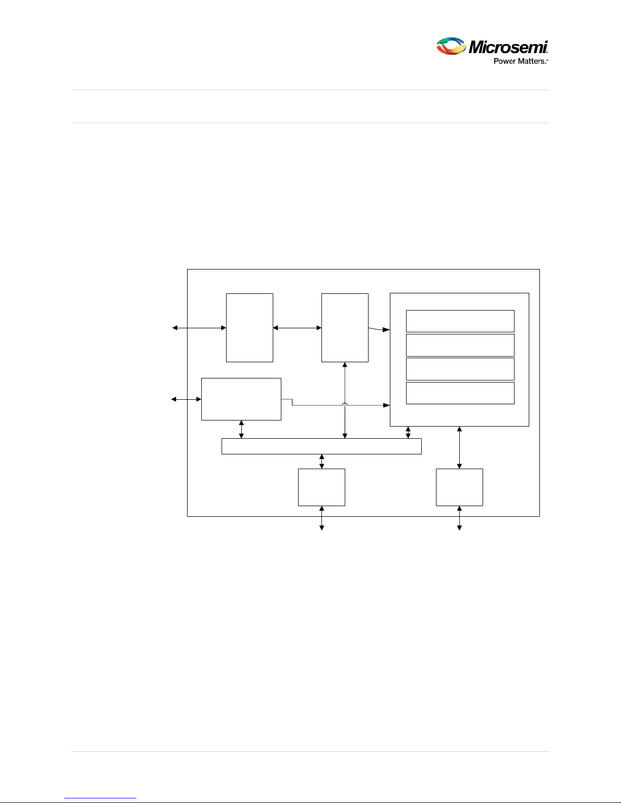
MiV_RV32IMAF_L1_AHB
JT AG I/F
External
Interrupts
AHB Memo ry I/F
AHB M MIO I/F
Debug
Transport
Module
Debug Module
E31 Cor e
Uncached TileLink Interconnect
TileLink to
AHB B ridg e
TileLink to
AHB B ridg e
Plat form-Level Interrupt
Controller
8 KB Instruction Cache
RV 32IM AF
Integer Mul tiplier/Divide r
8 KB D ata C ache
2 Introduction
2.1 Overview
The MiV_RV32IMAF_L1_AHB is a softcore processor designed to implement the RISC-V instruction
set for use in Microsemi FPGAs. The processor is based on the Coreplex E31 designed by SiFive,
containing a high-performance single-issue, in-order execution pipeline E31 32-bit RISC-V core. The
core includes an industry-standard JTAG interface to facilitate debug access, along with separate
AHB bus interfaces for memory access and support for 31 dedicated interrupt ports.
Figure 1 MiV_RV32IMAF_L1_AHB Block Diagram
50200801 Handbook 1 8
Page 9

HB0801: MiV_RV32IMAF_L1_AHB V2.0 Handbook
2.2 Features
• Designed for low power ASIC microcontroller and FPGA soft-core implementations.
• Integrated 8Kbytes instructions cache and 8Kbytes data cache.
• A Platform-Level Interrupt Controller (PLIC) can support up to 31 programmable interrupts with
a single priority level.
• Supports the RISC-V standard RV32IMAF ISA.
• On-Chip debug unit with a JTAG interface.
• Two external AHB interfaces for IO and memory.
2.3 Core Version
This Handbook applies to MiV_RV32IMAF_L1_AHB version 2.0.
Note: There are two accompanying manuals for this core:
• The RISC-V Instruction Set Manual, Volume 1, User Level ISA, Version 2.1
• The RISC-V Instruction Set Manual, Volume 2, Privileged Architecture, Version 1.10
2.4 Supported Families
• PolarFire®
• RTG4™
• IGLOO®2
• SmartFusion®2
2.5 Device Utilization and Performance
Utilization and performance data is listed in Table 1 for the supported device families. The data
listed in this table is indicative only. The overall device utilization and performance of the core is
system dependent.
Table 1 Device Utilization and Performance
Frequency
Family Sequential Combinatorial uSRAM LSRAM Math
SmartFusion2 6066 19073 34 8 2 58.38
IGLOO2 6626 18902 34 8 2 35.64
RTG4 6066 19076 46 8 2 44.27
PolarFire 6051 18973 67 10 2 91.46
Notes:
Performance numbers are for standard speed devices, except for PolarFire which uses the -1 speed.
Multi-pass place-and-route setting used set to 5.
(MHz)
50200801 Handbook 1 9
Page 10

HB0801: MiV_RV32IMAF_L1_AHB V2.0 Handbook
3 Functional Description
3.1 MiV_RV32IMAF_L1_AHB Architecture
Table 2 MiV_RV32IMAF_L1_AHB Architecture
Parameter Value Units Notes
ISA Support RV32IMAF
Cores 1
Harts/Cores 1
Branch prediction None
Multiplier occupancy 16 cycles 2-bit/cycles iterative multiply
I-cache size 8 KiB
I-cache associativity 1 way direct-mapped
I-cache line-size 64 bytes
D-cache size 8 KiB
D-cache associativity 1 way direct-mapped
D-cache line-size 64 bytes
Reset Vector configurable
External interrupts 31
PLIC Interrupt priorities 1
External memory bus AHB
External I/O bus AHB
JTAG debug transport address width 5 bits
Hardware breakpoints 2
Static Not Taken
Fixed priorities
50200801 Handbook 1 10
Page 11

HB0801: MiV_RV32IMAF_L1_AHB V2.0 Handbook
MiV_RV32IMAF_L1_AHB
JT AG I/F
External
Interrupts
AHB Memo ry I/F
AHB M MIO I/F
Debug
Transport
Module
Debug Module
E31 Cor e
Uncached TileLink Interconnect
TileLink to
AHB B ridg e
TileLink to
AHB B ridg e
Plat form-Level Interrupt
Controller
8 KB Instruction Cache
RV 32IM AF
Integer Mul tiplier/Divide r
8 KB D ata C ache
Figure 2 MiV_RV32IMAF_L1_AHB Block Diagram
3.2 MiV_RV32IMAF_L1_AHB Processor Core
MiV_RV32IMAF_L1_AHB is based on the E31 Coreplex Core by SiFive. The core provides a single
hardware thread (or hart) supporting the RISC-V standard RV32IMAF ISA and machine-mode
privileged architecture.
3.3 Pipelined Architecture
MiV_RV32IMAF_L1_AHB provides a high-performance single-issue in-order 32-bit execution
pipeline, with a peak sustainable execution rate of one instruction per clock cycle. The RISC-V ISA
standard M extensions add hardware multiply and divide instructions. MiV_RV32IMAF_L1_AHB has
a range of performance options including a fully pipelined multiply unit. An example of the pipeline
and its timing is as shown below.
50200801 Handbook 1 11
Page 12

HB0801: MiV_RV32IMAF_L1_AHB V2.0 Handbook
Figure 3 Example Five Stage Pipelined Architecture
Table 3 Example Pipeline Timing
3.4 Memory System
MiV_RV32IMAF_L1_AHB memory system supports configurable split first-level instruction and data
caches with full support for hardware cache flushing, as well as uncached memory accesses. External
connections are provided for both cached and uncached TileLink fabrics.
3.5 Platform-Level Interrupt Controller
MiV_RV32IMAF_L1_AHB includes a RISC-V standard platform-level interrupt controller (PLIC)
configured to support up 31 inputs with a single priority level.
3.6 Debug support through JTAG
MiV_RV32IMAF_L1_AHB includes full external debugger support over an industry-standard JTAG
port, supporting two hardware breakpoints.
50200801 Handbook 1 12
Page 13

HB0801: MiV_RV32IMAF_L1_AHB V2.0 Handbook
3.7 External AHB Interfaces
MiV_RV32IMAF_L1_AHB includes two external AHB interfaces, bridged from the internal TileLink
interfaces. The AHB memory interface is used by the cache controller to refill the instruction and
data caches. The AHB I/O interface is used for uncached accesses to I/O peripherals.
50200801 Handbook 1 13
Page 14

HB0801: MiV_RV32IMAF_L1_AHB V2.0 Handbook
4 Interface
4.1 Configuration Parameters
4.1.1 MiV_RV32IMAF_L1_AHB Configurable Options
There are two configurable options that apply to MiV_RV32IMAF_L1_AHB as shown in Table 4. If a
configuration other than the default is required, use the configuration dialog box in SmartDesign to
select appropriate values for the configurable options.
Table 4 MiV_RV32IMAF_L1_AHB Configuration Options
Parameter Valid Range Default Description
RESET_VECTOR_ADDR
(high halfword)
RESET_VECTOR_ADDR
(low halfword)
0x6000 - 0x8FFF 0x6000
0x0000 – 0xFFFC 0x0
4.1.2 Signal Descriptions
Signal descriptions for MiV_RV32IMAF_L1_AHB are defined in Table 5.
This is the address the processor will start executing
from after a reset. This address is byte aligned.
Table 5 MiV_RV32IMAF_L1_AHB I/O Signals
Port Name Width Direction Description
Global Signals
CLK 1 In
RESETN 1 In Synchronous reset signal. Active Low.
JTAG Interface Signals
TDI 1 In
TCK 1 In
TMS 1 In
TRST 1 In
TDO 1 Out
DRV_TDO 1 Out
System clock. All other I/Os are synchronous to this
clock.
Test Data In (TDI). This signal is used by the JTAG
device for downloading and debugging programs.
Sampled on the rising edge of TCK.
Test Clock (TCK). This signal is used by the JTAG
device for downloading and debugging programs.
Test Mode Select (TMS). This signal is used by the
JTAG device when downloading and debugging
programs. It is sampled on the rising edge of TCK to
determine the next state.
Test Reset (TRST). This is an optional signal used to
reset the TAP controllers state machine.
Test Data Out (TDO). This signal is the data which is
shifted out of the device during debugging. It is valid
on FALLING/RISING edge of TCK.
Drive Test Data Out (DRV_TDO). This signal is used to
drive a tristate buffer.
50200801 Handbook 1 14
Page 15

HB0801: MiV_RV32IMAF_L1_AHB V2.0 Handbook
Port Name Width Direction Description
External Interrupts Signals
IRQ 31 In
AHB Cached Memory Bus Master Interface
AHB_MST_MEM_HLOCK 1 Out
AHB_MST_MEM_HTRANS 2 Out
AHB_MST_MEM_HSEL 1 Out
AHB_MST_MEM_HWRITE 1 Out
AHB_MST_MEM_HADDR 32 Out
AHB_MST_MEM_HSIZE 3 Out
AHB_MST_MEM_HBURST 3 Out
AHB_MST_MEM_HPROT 4 Out
AHB_MST_MEM_HWDATA 32 Out
AHB_MST_MEM_HREADY 1 In
AHB_MST_MEM_HRESP 1 In
AHB_MST_MEM_HRDATA 32 In
AHB Non-cached Memory Bus Interface
AHB_MST_MMIO_HLOCK 1 Out
AHB_MST_MMIO_HTRANS 2 Out
AHB_MST_MMIO_HWRITE 1 Out
AHB_MST_MMIO_HADDR 31 Out
AHB_MST_MMIO_HSIZE 3 Out
AHB_MST_MMIO_HBURST 3 Out
AHB_MST_MMIO_HPROT 4 Out
AHB_MST_MMIO_HWDATA 32 Out
AHB_MST_MMIO_HREADY 1 In
AHB_MST_MMIO_HRESP 1 In
AHB_MST_MMIO_HRDATA 32 In
External interrupts from off-chip or peripheral
sources. These are level-based interrupt signals.
AHB Master interface for cached memory accesses.
AHB Master Interface for non-cached memory
accesses.
50200801 Handbook 1 15
Page 16

HB0801: MiV_RV32IMAF_L1_AHB V2.0 Handbook
5 Register Map and Descriptions
Table 6 Physical Memory Map (from E3 Coreplex Series)
Base Top Description
0x0000_0000 0x0000_00FF Reserved
0x0000_0100 Clear debug interrupt to component
0x0000_0104 Set debug interrupt to component Debug Area(4 KiB)
0x0000_0108 Clear halt notification from component
0x0000_010C Set halt notification from component
0x0000_0110 0x0000_03FF Reserved
0x0000_0400 0x0000_07FF Debug RAM (≤1KiB)
0x0000_0800 0x0000_0FFF Debug ROM (≤1KiB)
0x0000_1000 Reset
0x0000_1004 NMI
0x0000_1008 Reserved
0x0000_100C Configuration string address
0x0000_1010 0x0000_XXXX Trap vector table start Small ROM Area (60 KiB)
0x0000_XXXX Reset code
Interrupt handlers
Emulation routines
Register save/restore routines
0x0000_FFFF User ROM
0x0001_0000 0x3FFF_FFFF Reserved ROM/Misc./Reserved (≈1GiB)
0x4000_0000 0x43FF_FFFF Platform-Level Interrupt Control (PLIC)
0x4400_0000 0x47FF_FFFF Power/Reset/Clock/Interrupt (PRCI)
0x4800_0000 0x4800_0FFF Device Bank 0:
… On-Coreplex Devices (128 MiB)
0x4800_F000 0x4800_FFFF Device Bank 15:
0x4801_0000 0x4FFF_FFFF Reserved
0x5000_0000 0x5FFF_FFFF I/O Off-Coreplex Devices (768 MiB)
0x6000_0000 0x7FFF_FFFF AHB I/O Interface
0x8000_0000 0x8FFF_FFFC AHB Memory Interface RAM Area (256 MiB)
50200801 Handbook 1 16
Page 17

HB0801: MiV_RV32IMAF_L1_AHB V2.0 Handbook
6 Tool Flow
6.1 License
This core is being released under a modified Apache 2.0 license and is freely available through
Libero. Technical support is only provided for Microsemi Products.
6.1.1 RTL
Complete Verilog source code is provided for the core. A VHDL wrapper is provided for use in VHDL
projects. Allowing the core to be instantiated with SmartDesign. Simulation, Synthesis, and Layout
can be performed within Libero SoC.
6.2 SmartDesign
MiV_RV32IMAF_L1_AHB is preinstalled in SmartDesign IP Deployment design environment.
For more information on using SmartDesign to instantiate and generate cores, refer to the Using
DirectCore in Libero® SoC User Guide.
Figure 4 SmartDesign MiV_RV32IMAF_L1_AHB Instance View
6.3 Configuring MiV_RV32IMAF_L1_AHB in SmartDesign
The core is configured using the configuration GUI within SmartDesign, as shown in Figure 5.
Note: Leading zeros are suppressed, for example, 0x6000 0000 is displayed as 0x6000 0x0. The reset
vector is byte aligned.
50200801 Handbook 1 17
Page 18

HB0801: MiV_RV32IMAF_L1_AHB V2.0 Handbook
Figure 5 Configuring MiV_RV32IMAF_L1_AHB in SmartDesign
6.4 Debugging
CoreJTAGDebug V2.0.100 or later, is used to enable debugging of MiV_RV32IMAF_L1_AHB. This is
available in the Libero Catalog.
6.5 Simulation Flows
The user testbench for MiV_RV32IMAF_L1_AHB is not included in this release.
The MiV_RV32IMAF_L1_AHB RTL can be used to simulate the processor executing a program using a
standard Libero generated HDL testbench. An example subsystem for RTG4 is as shown in Figure 6.
Figure 6 RTG4 Example Simulation Subsystem
50200801 Handbook 1 18
Page 19

HB0801: MiV_RV32IMAF_L1_AHB V2.0 Handbook
6.6 Synthesis in Libero
To run synthesis on the core, set the SmartDesign sheet as the design root and click Synthesis in
Libero SoC.
6.7 Place-and-Route in Libero
After the design is synthesized, run the compilation and the place and-route tools. Click Layout in
the Libero SoC to invoke Designer. MiV_RV32IMAF_L1_AHB requires the place-and-route multi-seed
settings set to 5.
50200801 Handbook 1 19
Page 20

HB0801: MiV_RV32IMAF_L1_AHB V2.0 Handbook
Microsemi SoC FPGA Fabric
MiV _RV3 2IMA F_L1_A HB
JTAG I/F
AHB Memo ry I/F
AHB M MIO I/F
Cor eAHB Lite
Cor eAHB Lite
CoreAHBtoAPB3
Cor eAPB3
Cor eGPIO C oreT imer C oreS PI
DDR Controlle r
Cor eJTAG Debug
CCC
Reset Synchronizer
eNV M
LOC K
CLK
Off-chip
DDR
Mem ory
LEDs
Off-chip
SPI Peripherals
External
OSC
Push Button
Reset
JTAG
Header
RST
7 System Integration
7.1 Example System
Figure 7 MiV_RV32IMAF_L1_AHB Example System
7.2 Reset Synchronization
7.2.1 RST
All sequential elements clocked by CLK within MiV_RV32IMAF_L1_AHB, which require a reset
employ a synchronous reset topology. Since, most designs source CLK from a CCC/PLL, it is common
practice to AND the LOCK output of the CCC with the push button reset to generate the RST input for
MiV_RV32IMAF_L1_AHB. However, this results in the reset being deasserted when the CLK comes
up, hence the reset assertion is not clocked through the sequential reset elements and goes
unnoticed most commonly leading to the processor locking-up. To guarantee that the RST assertion
is seen by all sequential elements, a reset synchronizer is required on the RST input, as shown in
Figure 8.
50200801 Handbook 1 20
Page 21

HB0801: MiV_RV32IMAF_L1_AHB V2.0 Handbook
Reset Synchronizer
MiV_RV32IMAF_L1_AHB
Q
Q
SET
CLR
D
Q
Q
SET
CLR
D
Q
Q
SET
CLR
D
Q
Q
SET
CLR
D
Q
Q
SET
CLR
D
CCC
SYSRESET
LOCK
GLx
CLK
CL KINT
CL KINT
1
Processo r Subsy stem
RST
Figure 8 RST Reset Synchronization
The Verilog code snippet below implements the reset synchronizer block as shown in Figure 8. The
function of this block is to make the reset assertion and deassertion synchronous to CLK whilst
guaranteeing that the reset will be seen asserted for one or more CLK cycles within
MiV_RV32IMAF_L1_AHB to ensure that it is registered by all sequential elements.
module reset_synchronizer (
input clock,
input reset,
output reset_sync
);
reg [1:0] sync_deasert_reg;
reg [1:0] sync_asert_reg;
always @ (posedge clock or negedge reset)
begin
if (!reset)
begin
sync_deasert_reg[1:0] <= 2'b00;
end
else
begin
sync_deasert_reg[1:0] <= {sync_deasert_reg[0], 1'b1};
end
end
always @ (posedge clock)
begin
sync_asert_reg[1:0] <= {sync_asert_reg[0], sync_deasert_reg[1]};
end
assign reset_sync = sync_asert_reg[1];
endmodule
To include this synchronizer in your Libero design, select Create HDL from the Design Flow tab in
your Libero project. In the popup window, name the HDL file accordingly and select Verilog as the
HDL type whilst unchecking the option to Initialize file with standard template. Copy and paste the
Verilog code snippet above into this file and save the changes. From the Design Hierarchy tab drag
and drop the file into the SmartDesign sheet containing the MiV_RV32IMAF_L1_AHB instance and
connect up the pins as shown above.
7.2.2 TRST
No reset synchronization is required on this reset input as all sequential elements in the debug logic
within MiV_RV32IMAF_L1_AHB use an asynchronous reset topology.
50200801 Handbook 1 21
Page 22

HB0801: MiV_RV32IMAF_L1_AHB V2.0 Handbook
8 Design Constraints
Designs containing MiV_RV32IMAF_L1_AHB require the application of the following constraints in
the design flow to allow timing-driven placement and static timing analysis to be performed on
MiV_RV32IMAF_L1_AHB. The procedure for adding the required constraints in the Enhanced
Constraints flow in Libero v11.7 or later is as follows:
1. Double-click Constraints > Manage Constraints in the Design Flow window and click the Timing
tab.
Assuming that the system clock used to clock MiV_RV32IMAF_L1_AHB is sourced from a PLL,
select Derive to automatically create a constraints file containing the PLL constraints. Select Yes
when prompted to allow the constraints to be automatically included for Synthesis, Place-andRoute, and Timing Verification stages.
If changes are made to the PLL configuration in the design, update the contents of this file by
clicking Derive. Select Yes when prompted to allow the constraints to be overwritten.
2. In the Timing tab of the Constraint Manager window, select New to create a new SDC file, and
name it. Design constraints other than the system clock source derived constraints can be
entered in this blank SDC file. Keeping derived and manually added constraints in separate SDC
files allows the Derive stage to be reperformed if changes are made to the PLL configuration,
without deleting all manually added constraints in the process.
3. Calculate the TCK period and half period. TCK is typically 6 MHz when debugging with FlashPro,
with a maximum frequency of 30 MHz supported by FlashPro5. After completion, enter the
following constraints in the blank SDC file:
create_clock -name { TCK } \
-period TCK_PERIOD \
-waveform { 0 TCK_HALF_PERIOD } \
[ get_ports { TCK } ]
For example, the following constraints need to be applied for a design that uses a TCK frequency of 6
MHz:
create_clock -name { TCK } \
-period 166.67 \
-waveform { 0 83.33 } \
[ get_ports { TCK } ]
4. Next constraints must be applied to paths crossing the clock domain crossing between the TCK
and system clock clock domains. MiV_RV32IMAF_L1_AHB implements two clock domain
crossing FIFOs to handle the CDC and as such paths between the two clock domains may be
declared as false paths to prevent min and max violations from being reported by SmartTime.
set_false_path -from [ get_clocks { TCK } ] \
-to [ get_clocks { PLL_GEN_CLK } ]
set_false_path -from [ get_clocks { PLL_GEN_CLK } ] \
-to [ get_clocks { TCK } ]
50200801 Handbook 1 22
Page 23

HB0801: MiV_RV32IMAF_L1_AHB V2.0 Handbook
Where:
PLL_GEN_CLK is the name applied to the create_generated_clock constraint derived in
step 1 above.
5. Next constraints must be applied to the Floating Point Unit between the source clock and the
following signals:
i. MIV_RV32IMAF_L1_AHB_0/ChiselTop0/tile/rocket/fpuOpt/sfma/_T_28_data*
ii. MIV_RV32IMAF_L1_AHB_0/ChiselTop0/tile/rocket/fpuOpt/sfma/_T_28_exc*
For example:
set_multicycle_path -setup_only 2 -through {
MIV_RV32IMAF_L1_AHB_0/ChiselTop0/tile/rocket/fpuOpt/sfma/_T_28_data* }
set_multicycle_path -setup_only 2 -through {
MIV_RV32IMAF_L1_AHB_0/ChiselTop0/tile/rocket/fpuOpt/sfma/_T_28_exc* }
6. Associate all constraints files with the Synthesis, Place-and-Route and Timing Verification stages
in the Constraint Manager > Timing tab by selecting the related check boxes for the SDC files in
which the constraints were entered in.
50200801 Handbook 1 23
Page 24

HB0801: MiV_RV32IMAF_L1_AHB V2.0 Handbook
9 SoftConsole
SoftConsole Version 5.2 is required to use MiV_RV32IMAF_L1_AHB. Each SoftConsole project
requires the Hardware Abstraction Layer (HAL) version 2.1 or greater. The SoftConsole Release
Notes details how to set up a project for the MiV_RV32IMAF_L1_AHB core.
50200801 Handbook 1 24
Page 25

HB0801: MiV_RV32IMAF_L1_AHB V2.0 Handbook
10 Known Issues
10.1 Reset/Power Cycle the Target Hardware before each Debug Session
At the moment, the debugger cannot effect a suitable Mi-V RISC-V CPU/SoC reset at the start of
each debug session so one debug session may be impacted by what went before – for example, a
previous debug session leaves the CPU in an ISR and a subsequent debug session does not behave as
expected because of this. To mitigate this problem, it is recommended that the target
hardware/board is power cycled or otherwise reset before each new debug session.
50200801 Handbook 1 25
 Loading...