

Page 1

LX3301A/LX3302A
Auto Calibration User Guide
Preliminary
May 2018
Page 2

Contents
1 Revision History ............................................................................................................................. 1
1.1 Revision 1.0 ........................................................................................................................................ 1
2 Software Installation and Validation .............................................................................................. 2
3 Data Preparation for IPCE .............................................................................................................. 7
3.1 LX3301A/LX3302A EEPROM Setting for Data Capture ....................................................................... 9
3.2 How to Capture Data Using IPCE Manually ........................................................................................ 9
3.3 Manual Data Capture Preparation Using LX3302A ............................................................................. 9
3.4 Data Validation ................................................................................................................................. 12
4 Calibration Using IPCE .................................................................................................................. 13
4.1 Loading Data/EEPROM into IPCE ...................................................................................................... 13
4.2 Example Data and EEPROM Parameters Loaded ............................................................................. 14
4.3 Calibration Condition Settings .......................................................................................................... 14
4.4 Auto Calibration ............................................................................................................................... 15
4.5 Auto Calibration of Phase ................................................................................................................. 16
4.6 Save Calibrated Result into EEPROM ................................................................................................ 17
5 Data Capture Using IPCE with Microsemi Bench Control System (BCS) ...................................... 19
5.1 Alternative Way to Take Data Using Dongle Programmer ............................................................... 19
5.2 Collect Measurements with Default Parameters ............................................................................. 19
5.3 Save EEPROM Data to File ................................................................................................................ 21
Microsemi Proprietary and Confidential. LX3301A/LX3302A Auto Calibration User Guide Revision 1.0
Page 3

1 Revision History
The revision history describes the changes that were implemented in the document. The changes are
listed by revision, starting with the most current publication.
1.1 Revision 1.0
Revision 1.0 was published in May 2018. It was the first publication of this document.
Microsemi Proprietary and Confidential. LX3301A/LX3302A Auto Calibration User Guide Revision 1.0 1
Page 4
2 Software Installation and Validation
The following section describes how to install and validate the software for the LX3301A/LX3302A
device.
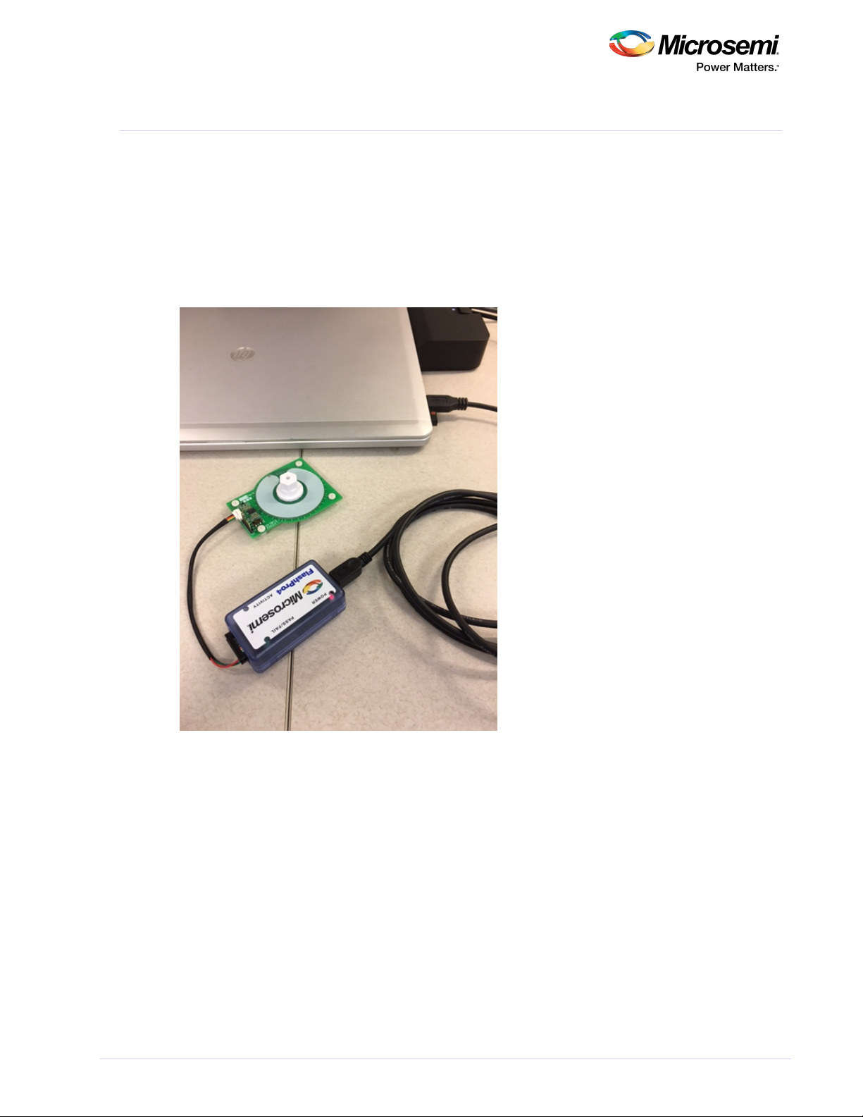
1. Connect the dongle to the computer.
2. Connect the sensor PCB to the dongle.
3. Place your target at a desired air gap.
The first three steps are shown in the following image.
Figure 1 • System Setup
4. Set up your bench system to take measurements.
Microsemi Proprietary and Confidential. LX3301A/LX3302A Auto Calibration User Guide Revision 1.0 2
Page 5
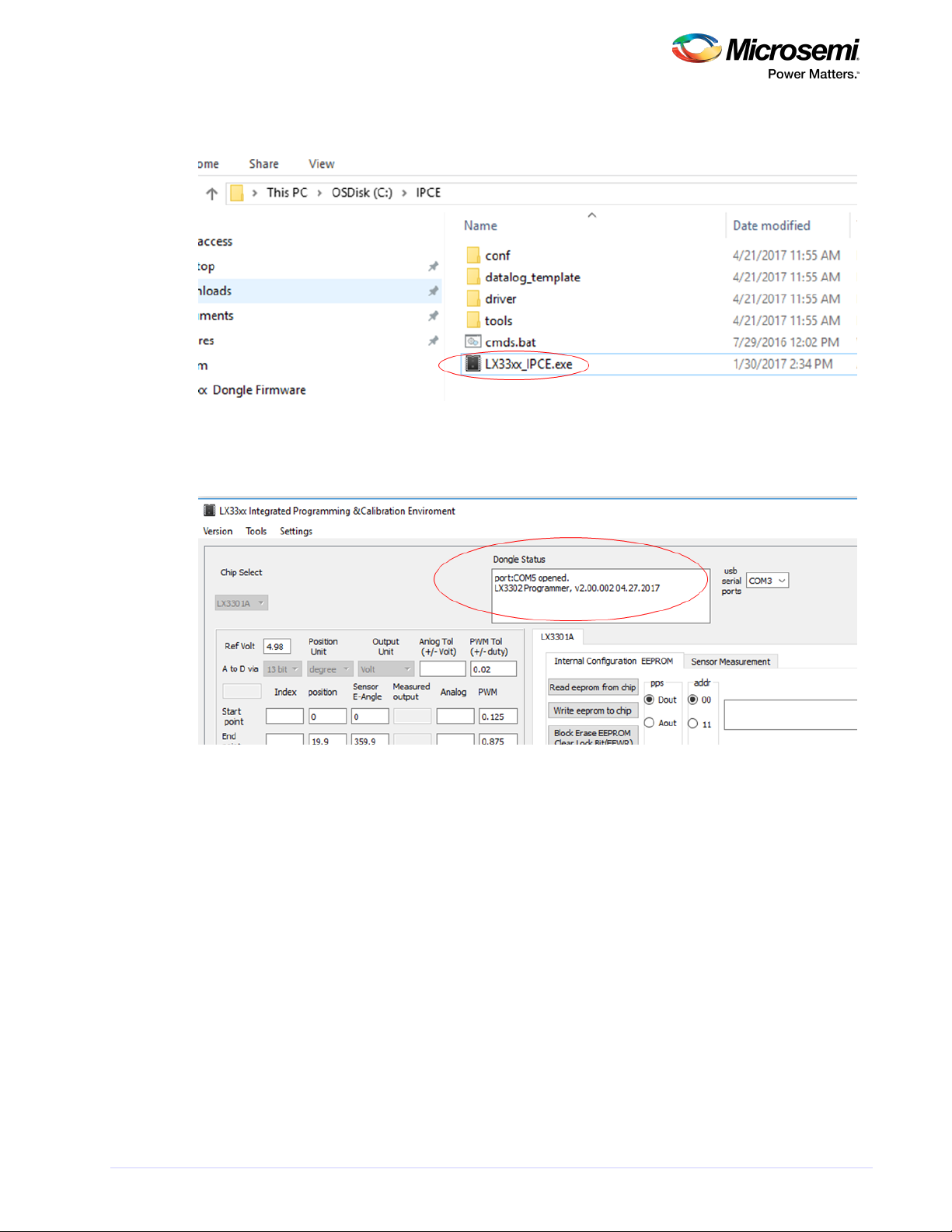
5. Launch Integrated Programming and Calibration Environment (IPCE), as shown.
Figure 2 • Launch IPCE
6. Verify that the port has opened, as shown.
Figure 3 • Verify Port Has Opened
Note: If it cannot recognize the dongle, then install the driver provided using device manager, then
unplug and replug the USB cable.
Microsemi Proprietary and Confidential. LX3301A/LX3302A Auto Calibration User Guide Revision 1.0 3
Page 6
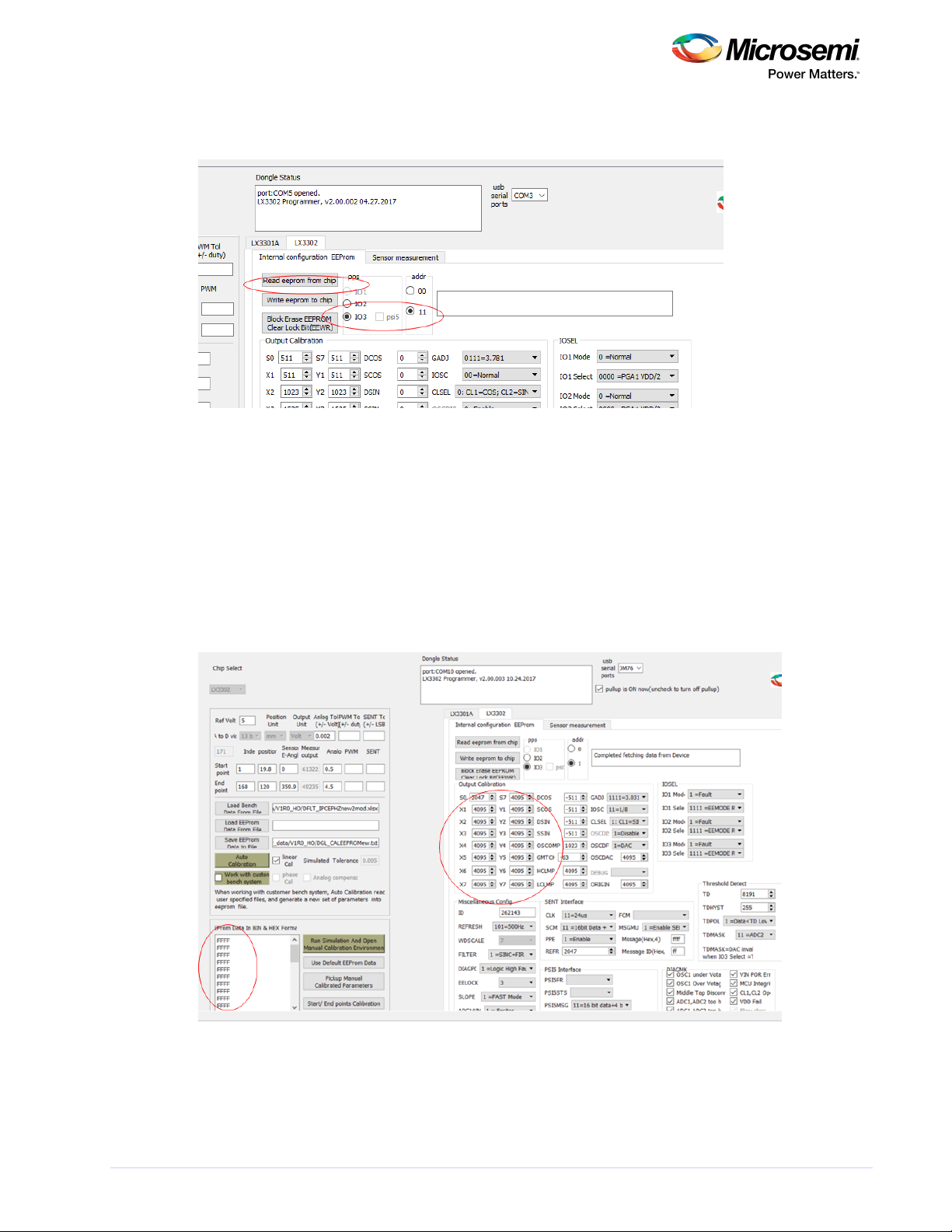
7. Read EEPROM from the chip (choose AOUT 11 for LX3301A or IO3 11 for LX3302A), as shown.
Figure 4 • Read EEPROM from Chip
If the result is the same as default parameters or previously programmed ones, then communication has
been done correctly.
If the result is as shown in the following three images, then communication has not been done correctly.
Note: Place the target with proper air gap distance if it won't read EEPROM correctly. Then, try to read
again. Adjust the target until it reads correctly.
The following image shows an example of a communication error. The sensor board is not connected or
AOUT/IO3 is stuck high. All data is FFFF.
Figure 5 • Example Communication Error
Microsemi Proprietary and Confidential. LX3301A/LX3302A Auto Calibration User Guide Revision 1.0 4
Page 7
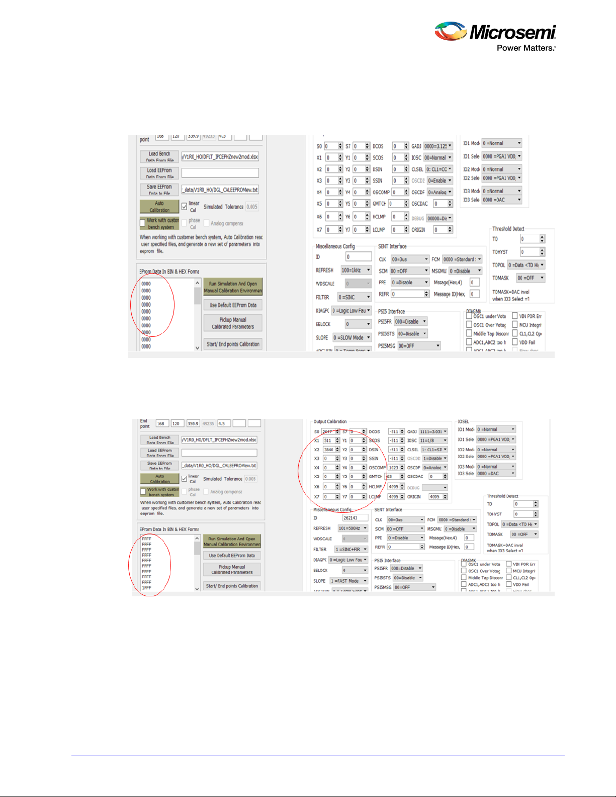
The following image shows an example in which the IC detects fault or AOUT/IO3 is stuck at 0 V. The
sensor board is not connected or AOUT/IO3 is stuck high. All data is 0000.
Place the target in the proper position or fix AOUT/IO3 shorted GND.
Figure 6 • Example of IC Detects Fault or AOUT/IO3 Stuck at 0 V
The following image shows an example of IC unpowered (VIN). VIN is not connected. Data is garbled.
Figure 7 • Example of IC Unpowered
Microsemi Proprietary and Confidential. LX3301A/LX3302A Auto Calibration User Guide Revision 1.0 5
Page 8
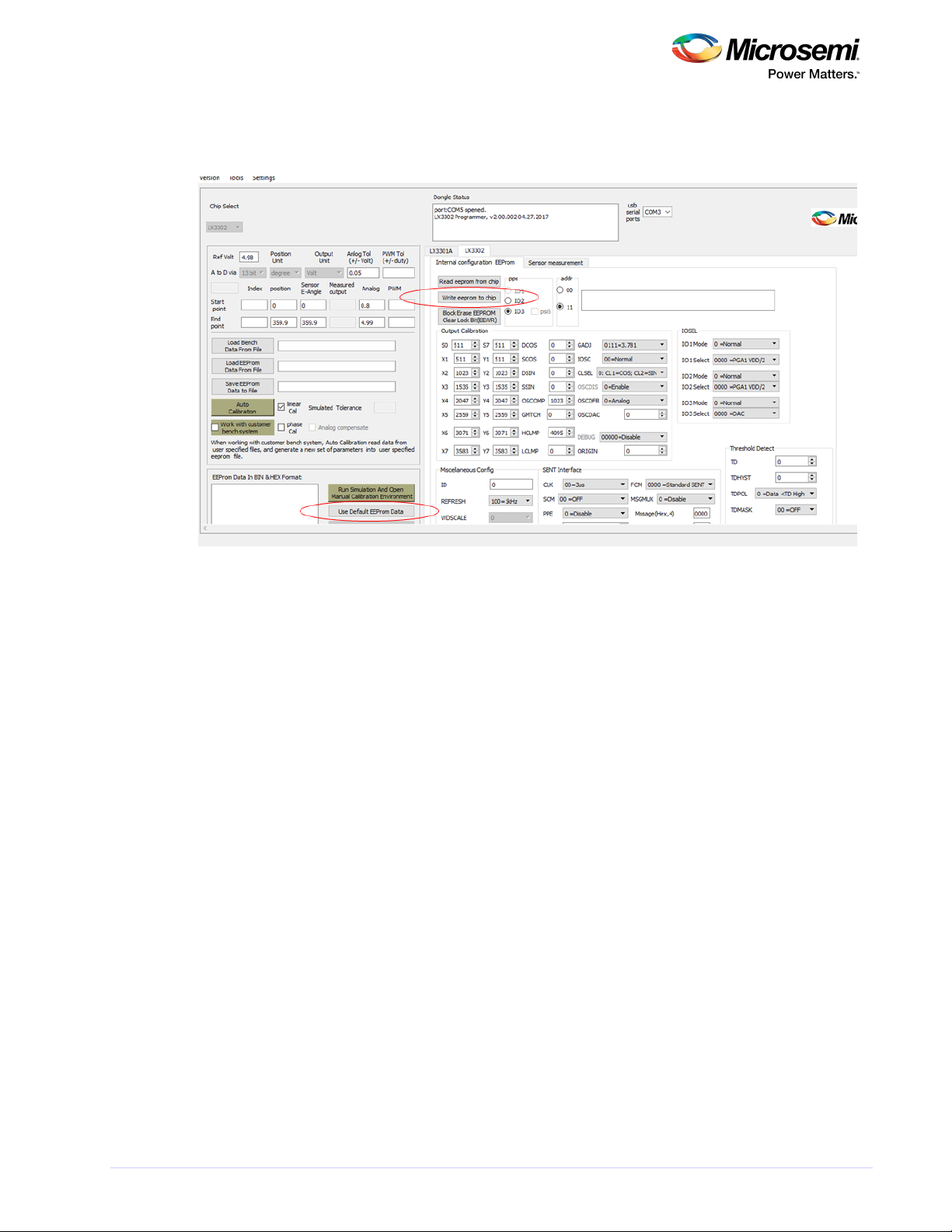
8. Use the default EEPROM data and write this default EEPROM data to the chip, as shown in the
following image.
Figure 8 • Write Default EEPROM Data to Chip
Microsemi Proprietary and Confidential. LX3301A/LX3302A Auto Calibration User Guide Revision 1.0 6
Page 9

3 Data Preparation for IPCE
The following section describes how to prepare the data for IPCE.
IPCE supports analog, PWN, and SENT data formats.
The following image shows an example of the analog data format for analog output. It provides the data
format template.
Figure 9 • Analog Data Format for Analog Output
The following image describes the data format for analog data.
Figure 10 • Data Format for Analog Data
SP position—Start point position on the data (target position). See the red arrow.
EP position—End point position on the data. See the blue arrow.
SP AOUT(V)—Start point AOUT voltage (for example, 0.5). See the green arrow.
EP AOUT(V)—End point AOUT voltage (for example, 4.5). See the purple arrow.
VIN—VIN voltage supplied to the sensor board.
A_Tolerance (V)—Allowable tolerance for auto calibration.
The following list describes data preparation using the Excel data template.
Position value must be arranged lowest to highest value (no negative slope).
SP_AOUT—Must be a low setting value.
Microsemi Proprietary and Confidential. LX3301A/LX3302A Auto Calibration User Guide Revision 1.0 7
Page 10

EP_AOUT—Must be a high setting value.
Regardless of if the slope is negative or positive of the desired curve, SP must be a low value and
EP must be a high value.
SP position—Position of SP_AOUT value.
EP position—Position of EP_AOUT value.
Example—4.5 V (3 mm) –0.5 V (20 mm) (negative slope). SP_AOUT= 0.5 V, EP_AOUT= 4.5. SP
position= 20, EP position=3.
Figure 11 • Data Format for Analog
The following image shows the data format for PWM data.
Figure 12 • Data Format for PWM Data
SP position—Start point position on the data (target position). See the red arrow.
EP position—End point position on the data. See the blue arrow.
SP PWMDuty—Start point PWM duty (for example, 0.9). See the green arrow.
EP PWMDuty—End point PWM duty (for example, 0.1). See the purple arrow.
VIN—N/A.
PWM_Tolerance (duty)—Allowable tolerance for auto calibration.
Microsemi Proprietary and Confidential. LX3301A/LX3302A Auto Calibration User Guide Revision 1.0 8
Page 11

Figure 13 • Data Format for PWM Data
3.1 LX3301A/LX3302A EEPROM Setting for Data Capture
If analog output mode is selected, use measurement equipment to collect higher-resolution data.
Use the EEPROM setting for uncalibrated data collection.
Click , then click .Use Default EEPROM Data Write eeprom to chip
Figure 14 • EEPROM Setting
3.2 How to Capture Data Using IPCE Manually
If data cannot be captured by a motorized automatic system, then it can be done manually using IPCE.A
position measurement tool is required to get an accurate position value (linear or rotary/angular).After
locating the target at a given position, then record this value.Then, collect data using the customer’s
bench test system.Replace the position/measured data into template file.
3.3 Manual Data Capture Preparation Using LX3302A
The following steps prepare to manually capture the data using the LX3302A.
1. Configure IO2 as SENT and IO3 as DAC and enable debug by choosing ADC1, as shown.
Microsemi Proprietary and Confidential. LX3301A/LX3302A Auto Calibration User Guide Revision 1.0 9
Page 12

Figure 15 • Manual Data Capture Configuration
2. In the tab, check IO2 and IO3 to see the measurements, as shown.Sensor measurement
Figure 16 • Sensor Measurements Tab
3. Press to record the data. Move the target to the next position and repeat this step until Capture Data
all desired data is captured.
Microsemi Proprietary and Confidential. LX3301A/LX3302A Auto Calibration User Guide Revision 1.0 10
Page 13

4. Press the button if data is captured by IPCE.Save Datalog
Figure 17 • Update Target Output
After completing a run with default parameter, save all the data in one of the templates shown
previously; or, if you have taken this data through the dongle, you can simply press .Save Datalog
Figure 18 • Save DataLog
Microsemi Proprietary and Confidential. LX3301A/LX3302A Auto Calibration User Guide Revision 1.0 11
Page 14

3.4 Data Validation
After data collection, check if the data is valid to use.
In Excel, plot and check that the curve is not intermittent and does not have drops.
The following is an example of invalid data.
Figure 19 • Invalid Data
Microsemi Proprietary and Confidential. LX3301A/LX3302A Auto Calibration User Guide Revision 1.0 12
Page 15

4 Calibration Using IPCE
The following section describes calibration using IPCE.
4.1 Loading Data/EEPROM into IPCE
1. In the IPCE GUI, click , as shown.Load Bench Data From File
Figure 20 • Load Bench Data From File
2. Select the data file captured and prepared as given data format (Excel).
3. When the following window appears, click .OK
Figure 21 • Success Window
3. Click , as shown.Load EEProm Data From File
Figure 22 • Load EEProm Data From File
4. Select or click . Finally, data and EEPROM parameters are eeprom data stored Read eeprom from chip
loaded into IPCE to do autocal and simulation.
Microsemi Proprietary and Confidential. LX3301A/LX3302A Auto Calibration User Guide Revision 1.0 13
Page 16

4.2 Example Data and EEPROM Parameters Loaded
The following image shows an example of loaded data and EEPROM parameters.
Figure 23 • Example Loaded Data and EEProm Para Loaded
4.3 Calibration Condition Settings
The following image shows the calibration condition settings. The example given is 35 mV. This means
that any given position on the output could be accurate within 35 mV.
IF ANALOG (DAC) output is used, measure VIN from the sensor board connector.
Analog Tol= the Autocal system will calibrate up to this accuracy.
Figure 24 • Calibration Condition Setting
Microsemi Proprietary and Confidential. LX3301A/LX3302A Auto Calibration User Guide Revision 1.0 14
Page 17

4.4 Auto Calibration
Once the bench data from the file is loaded, phase and calibration can be completed.
1. Check the box for both and .linear Cal phase Cal
2. Click .Auto Calibration
Figure 25 • Auto Calibration
Calibration is complete. The result is shown in Simulated Tolerance.
The following image shows auto calibration of phase and gain.
Figure 26 • Auto Calibration of Phase and Gain
Microsemi Proprietary and Confidential. LX3301A/LX3302A Auto Calibration User Guide Revision 1.0 15
Page 18

4.5 Auto Calibration of Phase
The following steps and image describe how to auto calibrate phase.
1. Uncheck the box for and check the box for .linear Cal phase Cal
2. Press . Then, the new values of SSIN, SCOS, and GMTCH should appear.Auto Calibration
3. Burn this into the IC by .write Eeprom to chip
Figure 27 • Auto Calibration of Phase
5. Click to open the manual calibration Run Simulation And Open Manual Calibration Environment
environment, shown in the following image.
Figure 28 • Manual Calibration Environment
Microsemi Proprietary and Confidential. LX3301A/LX3302A Auto Calibration User Guide Revision 1.0 16
Page 19

6. Check the box for to get the MaxErr number that IPCE can achieve. Select to SIM_OUT_ERROR Zoom
see error versus position. The following image shows an example simulation.
Figure 29 • Example Simulation
4.6 Save Calibrated Result into EEPROM
The following steps describe how to save the calibrated result into EEPROM.
1. When the auto calibration simulation result is acceptable, restore all test modes into normal mode.
2. Uncheck all boxes, except on DIAGMK, as shown.VIN POR Err
Figure 30 • Uncheck Boxes
3. For IO1, IO2, and IO3 Mode, select , as shown. 0 =Normal
Figure 31 • Normal Mode
Microsemi Proprietary and Confidential. LX3301A/LX3302A Auto Calibration User Guide Revision 1.0 17
Page 20

4. For DEBUG, select , as shown.00000=Disabled
Figure 32 • Debug
5. For REFRESH, select the desired rate, as shown.
Figure 33 • Refresh
6. Click .write eeprom to chip
7. Click . Then, select the proper file save location and type in the filename to Save EEProm Data to File
store (for example, SN_01_Final_eeprom).
Recapture the data with calibrated EEPROM parameters and verify the result.
Repeat the previous steps, skipping auto calibration. If the result is acceptable, then the process is
complete.
Microsemi Proprietary and Confidential. LX3301A/LX3302A Auto Calibration User Guide Revision 1.0 18
Page 21

5 Data Capture Using IPCE with Microsemi Bench Control System
(BCS)
The following section describes how to use the Microsemi bench control system (BCS) to capture data.
5.1 Alternative Way to Take Data Using Dongle Programmer
The following instructions enable the programmer dongle to take measurements.
1. Configure IO2 as SENT.
2. Configure IO3 as DAC.
3. Enable debug by choosing ADC1.
4. Select to write these parameters to EEPROM.Write eeprom to chip
5. Read EEPROM to verify these parameters.
6. Select the Sensor measurement tab to view the measurements.
5.2 Collect Measurements with Default Parameters
At this moment in calibration, measurement data needs to be collected using default parameters. Run
the bench system and collect data simultaneously. You can choose to make your own measurements
through external test equipment. Depending on what type of data you want to collect (analog or digital),
you can use the Aout and Dout pins. For LX3302A, use IO3 as the Aout and IO2 as Dout. Data taken must
be in one of the two formats, as shown in the following image, to be compatible with the auto
calibration function. At least 18 measurements are required, no maximum limit.
Figure 34 • Data Formats
Microsemi Proprietary and Confidential. LX3301A/LX3302A Auto Calibration User Guide Revision 1.0 19
Page 22

The following image shows how to set the calibration condition in the datalog file.
Figure 35 • Calibration Condition Setting
The following image shows an example datafile with a negative slope.
Figure 36 • Example Datafile with Negative Slope
Microsemi Proprietary and Confidential. LX3301A/LX3302A Auto Calibration User Guide Revision 1.0 20
Page 23

The following image show an example of post autocal.
Figure 37 • Example of Post Autocal
5.3 Save EEPROM Data to File
After you have saved the default parameters file, save the EEPROM data to file.
Save the current EEPROM parameters. You can do this by simply clicking , as Save EEProm Data to File
shown in the following image. Name this .Default eeprom parameters
Figure 38 • Save EEProm Data to File
Microsemi Proprietary and Confidential. LX3301A/LX3302A Auto Calibration User Guide Revision 1.0 21
Page 24

Microsemi Corporate Headquarters
One Enterprise, Aliso Viejo,
CA 92656 USA
Within the USA: +1 (800) 713-4113
Outside the USA: +1 (949) 380-6100
Fax: +1 (949) 215-4996
Email: sales.support@microsemi.com
www.microsemi.com
© 2018 Microsemi Corporation. All rights reserved. Microsemi and the
Microsemi logo are trademarks of Microsemi Corporation. All other
trademarks and service marks are the property of their respective owners.
Microsemi makes no warranty, representation, or guarantee regarding the information contained herein or the suitability of its products and s ervices
for any particular purpose, nor does Microsemi assume a ny liability whatsoever arising out of the app lication or use of any product or circuit. The
products sold hereunder and an y other products sold by Microsemi have been s ubject to limited testing and should not be us ed in conjunction with
mission-critical equipment or applications. Any performance specifications are believed to be reliable but are not verified, and Buyer must condu ct and
complete all performance and other testing of the products, alone and together with, or installed in , any end-products. Buyer shall not rely on any data
and per formance specifications or para meters provided by Microsemi. It is the Buyer's responsibility to ind ependently determine suitability of any
products and to test and verify the same. The information provided by Microsemi hereunder is provided "as is, where is" and with all faults, and the
entire risk associated with such information is entirely with the Buyer. Microsemi does not grant, explicitly or implicitly, to any party any patent rights,
licenses, or any other IP rights, whether with regard to such information itself or anything described by such information. Information provided in this
document is proprietar y to Microsemi, and Micr osemi reserves the right to make any changes to the information in this document or to any products
and services at any time without notice.
Microsemi C orporation (Nasdaq: MSCC) offers a compre hensive portfolio of semi conductor and sy stem solutions f or aerospace & defense,
communications, data center and industrial markets. Products include high-performance and radiation-ha rdened a nalog mi xed-signal integrated
circuits, FPGAs, So Cs and ASICs; power managemen t products; timing and synchr onization devices and precise time solutions, setting the world's
standard for time; voice processing devices; RF solutions; discrete components; enterprise storage and communication solutions; security technologies
and scalable anti-ta mper products; Ethernet solutions; Power-over-Ethernet ICs and midspans; as well as custom des ign capabilities and services.
Microsemi is headquartered in Aliso Viejo, California, and has approximately 4,800 employees globally. Learn more at www.microsemi.com.
MSCC-0236-UG-01000-1.0-0518
Microsemi Proprietary and Confidential. LX3301A/LX3302A Auto Calibration User Guide Revision 1.0 22
 Loading...