

Page 1
ATS-6501 T-Flex
ATS-6501B T-Flex
ATS-6501B SAASM T-Flex
GPS Time & Frequency Standard
Users Guide
Software Version 5.2.X
Release V
Jan 2017
Page 2

Page 3

DOC 6501_Release V
ATS-6501 Users Guide
Revision History
Revision Description Date Approved
A Initial release 02/10/09 KM
B Command updates 05/23/09 GAR
C Add 4395A-5, NASA 36 10/02/09 GAR
D Added support contact information 11/10/09 GAR
E Add 4372A, DC power correction 2/24/10 GAR
F Add C of C 3/29/10 GAR
G Added 4393A TIC Card, tagps, other updates 6/17/10 GAR
H Add 1 MHz module. Emphasize need to save user settings.
Add diag log selections. Change software update
procedure
J Add SAASM version 01/26/11 GAR
K Two-Way over Fiber 06/06/11 GAR
L OS Upgrade. Command/status changes. Modified GPS
Tracking Alarms. Modified alarm structure for latching
and non-latching alarm types.
M Added SNMP Functionality. Updated help menu
Added configuration not readable alarm.
Changed to status reference:frequency:external
N Introduction of the 4395B-(1,5,10) and 4385B
Correct command for NTP status.
M Added SNMP Functionality. Updated help menu.
Added configuration not readable alarm.
Changed to status reference:frequency:external
O Added the ability to recover time without an external GNSS
reference. Added Timescale commands, settings, and
status. Added System Configuration (syscfg) Files
P Added support for 4396A/4397A 2MHz Card
Fixed issues with GPS logging on the SAASM Receiver.
Microsemi acquisition.
Q Added operations recommendation when using an external
reference
R Added support for 4394A-ECL Card 3/10/14 WF
S Added support for 4391 Card
Leap-Second info for setting time manually
T NTP Specs, SNMP Function updates, Deterministic PLL,
6300 Series Chassis Monitoring (SMCP), 4376A RS-422
PPS Card, 4383A DC Input card
T, Rev 1 4374A T1 Card 2/18/2015 KM
U SNMP/NTP Authentication, RADIUS, User Accounts,
SSH Keys. Steer Sources, 4394A Specs., Syscfg
V 4337A Card , SMCP updates 01/12/2017 WF
12/14/10 GAR
11/08/11 KM
04/18/12 WF
1/25/13 WF
04/18/12 WF
9/6/2013 KM
12/31/2013 KM
1/20/14 GR
5/27/14 KM
2/5/2015 KM
10/10/2016 KM
i
Page 4

ATS-6501 Users Guide
DOC 6501_Release V
Table of Contents
1 General Information ......................................................................................................... 1
1.1 Introduction .......................................................................................................... 1
1.2 Ordering Information ........................................................................................... 1
2 Installation ........................................................................................................................ 4
2.1 Powering on the ATS-6501 .................................................................................. 4
2.2 Communicating with the ATS-6501 .................................................................... 5
2.2.1 DHCP ............................................................................................................ 5
2.2.2 Static IP Addresses ....................................................................................... 5
2.2.2.1
2.2.2.2
2.2.3 Setting a Static IP Address ............................................................................ 6
2.2.4 Firewall Settings ........................................................................................... 7
2.2.5 USB Ports ...................................................................................................... 8
2.2.6 RADIUS Authentication ............................................................................... 8
2.3 Antenna Installation ............................................................................................. 9
2.3.1 Antenna Location .......................................................................................... 9
2.3.2 Setting the Antenna Voltage ....................................................................... 11
2.3.3 Outdoor Antenna Grounding ...................................................................... 12
2.3.4 Antenna Mask Angle .................................................................................. 12
2.3.5 Positioning Modes ...................................................................................... 13
2.3.5.1
2.3.5.2
2.3.5.3
2.4 ATS-6501 Installation ........................................................................................ 16
2.4.1 Power Supplies ............................................................................................ 17
2.4.2 Input/Output Cards ...................................................................................... 17
2.4.2.1 4394A (PPS/DC IRIG) ................................................................................ 17
2.4.2.2 4376A RS-422 PPS ...................................................................................... 19
2.4.2.3 4394A-ECL (PPS-ECL) ............................................................................... 21
2.4.2.4 4391 Code Generator ................................................................................... 22
2.4.2.5 4395A-10 / 4395B-10 10MHz Card ............................................................ 29
2.4.2.6 4395A-5 / 4395B-5 5MHz Card .................................................................. 29
2.4.2.7 4395A-1 / 4395B-1 1MHz Card .................................................................. 30
2.4.2.8 4387A, 4387A-6V, and 4387A-1V (Modulated IRIG/NASA36) ............... 30
2.4.2.9 4396A/4397A 2MHz Output Card ............................................................... 32
2.4.2.10 4394A T1 (1.544MHz) Output Card .......................................................... 32
2.4.2.11 4372A-T Fiber Output Card (Two-Way) .................................................... 33
2.4.2.12 4393A Time Interval Counter (TIC) Card .................................................. 34
2.4.2.13 4383A IRIG Input Card .............................................................................. 35
2.4.2.14 4337A Modulated IRIG with Epoch Support ............................................. 36
2.5 Antenna Delay Calibration ................................................................................. 37
2.6 On Time Point (OTP) ......................................................................................... 38
2.7 Using an External Frequency Reference ............................................................ 39
Network ..................................................................................................... 5
Console Cable ........................................................................................... 5
Dynamic Position Mode .......................................................................... 13
Auto Position Mode ................................................................................ 13
Manual Position Mode ............................................................................ 15
ii
Page 5

ATS-6501 Users Guide
DOC 6501_Release V
2.7.1 Reference Type ........................................................................................... 39
2.7.2 hp5071A Communications ......................................................................... 40
2.7.3 Unmonitored Clocks ................................................................................... 40
2.7.4 Selecting the External Reference ................................................................ 40
2.8 Using the Time Scale Reference ........................................................................ 41
2.9 Setting the System Time Manually .................................................................... 45
2.9.1 Force Time .................................................................................................. 45
2.9.2 Deterministic Phase Lock Loop (DPLL) .................................................... 45
2.9.3 External Reference ...................................................................................... 48
2.9.4 Disable the GPS Tracking Alarms .............................................................. 48
2.10
User Configuration Files ................................................................................ 48
2.10.1 Factory / Default User Configuration Files ................................................ 48
2.10.2 Diff Command ............................................................................................ 50
2.10.3 FTP and Real-Time (rt) Configuration Files .............................................. 50
2.10.4 System Configuration Files (Syscfg) .......................................................... 52
2.10.5 Node Configuration File (node.cfg) ............................................................ 53
3 Operations ...................................................................................................................... 55
3.1 Front Panel ......................................................................................................... 55
3.1.1 Power Supply Indicators .................................................................................. 55
3.1.2 Alarm Indicator ........................................................................................... 55
3.1.3 Oscillator Locked (Osc Lock) Indicator ..................................................... 56
3.1.4 GPS Tracking Indicator .............................................................................. 56
3.1.4 NTP Locked Indicator ................................................................................. 57
3.1.5. Outputs Enabled Indicator .......................................................................... 57
3.1.6. KEY ACTIVE Indicator (SAASM) ............................................................ 57
3.1.7. ZEROIZE Button (SAASM) ....................................................................... 58
3.1.8. CRYPTO KEY Programming Connector (SAASM) ................................. 58
3.1.9. Fans ............................................................................................................. 58
3.1.10.
3.1.11.
Flash Card ............................................................................................... 58
Display Button ......................................................................................... 58
3.2 Rear Panel .......................................................................................................... 59
3.3 Software ............................................................................................................. 60
3.3.1 Current Version ........................................................................................... 60
3.3.2 Software Updates ........................................................................................ 60
3.3.2.1
3.3.2.2
Flash Card Replacement .......................................................................... 61
Remote Software Update ........................................................................ 61
3.3.3 GPS Firmware Updates ............................................................................... 63
3.3.4 Declassifying the System ............................................................................ 63
3.4 User Interfaces .................................................................................................... 63
3.4.1 Operating System ........................................................................................ 63
3.4.2 Telnet .......................................................................................................... 63
3.4.3.1
3.4.3.2
Real Time Data Port (1135) .................................................................... 64
Command Port (1700) ............................................................................. 64
3.4.3.3 Diagnostic Port (1800) ................................................................................. 67
3.4.3.4
3.4.3.5
Status Port (1900) .................................................................................... 68
Average TIC Data Port (2100) ................................................................ 68
iii
Page 6

ATS-6501 Users Guide
3.4.3.6
Raw TIC Data Port (2101) ...................................................................... 69
DOC 6501_Release V
3.4.4 File Transfer Protocol (FTP) ....................................................................... 70
3.4.5 Network Time Protocol (NTP) ................................................................... 70
3.4.5.1
3.4.5.2
3.4.5.3
NTP Authentication ................................................................................. 70
NTP Server .............................................................................................. 71
NTP Clients ............................................................................................. 73
3.4.6 Simple Network Management Protocol (SNMP) ....................................... 73
3.4.6.1
3.4.6.2
3.4.6.3
3.4.6.4
3.4.6.5
Management Information Base (MIB) .................................................... 73
SNMP2 .................................................................................................... 73
SNMP3 .................................................................................................... 73
Testing SNMP3 ....................................................................................... 74
SNMP Traps ............................................................................................ 75
3.4.7 Secure Shell (SSH) Authentication ............................................................. 75
3.4.7.1
3.4.7.2
Creating a SSH New Key ........................................................................ 75
Transferring a SSH Key .......................................................................... 75
3.5 Local User Accounts .......................................................................................... 75
3.6 Status Command ................................................................................................ 76
3.7 GPS Data Logging (Not available on SAASM Type I) ..................................... 77
3.7.1 FTP Data Logging ....................................................................................... 77
3.7.2 Real Time Data Logging ............................................................................. 80
3.8 WAAS Satellites (Not available in SAASM version) ........................................ 81
3.9. System Verification ............................................................................................ 82
4 Theory of Operations ...................................................................................................... 96
4.1 Generation of Timing Signals ............................................................................ 96
4.2 GPS ..................................................................................................................... 96
4.3 Deterministic PLL (6501B only) ........................................................................ 96
4.4 Output Signals .................................................................................................... 97
4.5 GPS Data Collection (Not available in SAASM Type 1) .................................. 97
4.6 Startup Sequence ................................................................................................ 98
5 Maintenance ................................................................................................................. 100
5.1 Internal Inspection ................................................................................................ 100
5.2 Antenna and Antenna Cable Inspection ................................................................ 100
5.3 Fan Filter ............................................................................................................... 101
6. Troubleshooting ............................................................................................................ 102
6.1 Front Panel Indications ..................................................................................... 102
6.2 Alarm Light ...................................................................................................... 102
6.2.1 Power Supplies .......................................................................................... 103
6.2.2 Outputs Enabled ........................................................................................ 104
6.2.3 GPS Performance ...................................................................................... 105
6.2.3.1
6.2.3.2
Poor GPS Receiver Performance .......................................................... 106
GPS Not Tracking ................................................................................. 107
6.2.4 Internal Clocks .......................................................................................... 108
6.2.5 External Reference .................................................................................... 109
6.2.6 NTP Server ................................................................................................ 112
6.2.7. PTD Value is Noisy .................................................................................. 112
6.2.8 Over Temperature and Fans ...................................................................... 112
iv
Page 7

ATS-6501 Users Guide
DOC 6501_Release V
6.2.9 PPS Outputs .............................................................................................. 113
6.2.10 IRIG Outputs ................................................................................................ 114
6.2.11 NASA36 Outputs ......................................................................................... 115
6.2.12 TIC Measurements ....................................................................................... 116
6.2.13 4391 Code Generator ................................................................................... 116
6.2.14 Software Update Failure .............................................................................. 117
6.2.15 Configuration Not Readable ........................................................................ 117
6.3 Communication Problems ................................................................................ 117
6.3.1 LAN .......................................................................................................... 117
6.3.2 USB-to-Serial Adapter (94000-115200) (Command Port) ....................... 117
6.3.3 External Reference Adapter (94001-5071A) ............................................ 118
6.4 Syslog Command ............................................................................................. 118
6.5 System Configuration Issues (syscfg) .............................................................. 119
6.6 Troubleshooting Summary ............................................................................... 119
Appendix A System Specifications .............................................................................................. 121
Appendix B Status Command Fields ........................................................................................... 129
Appendix C Status Port (1900) Example ..................................................................................... 135
Appendix D Detailed Command Information .............................................................................. 147
Appendix E System Recovery Without GNSS ............................................................................ 193
Appendix F System Monitoring and Control Protocol (SMCP) .................................................. 196
F.1 Description ....................................................................................................... 196
F.2 Configuring SMCP ........................................................................................... 197
F.3 NodeIDs ........................................................................................................... 200
F.4 Troubleshooting ............................................................................................... 203
F.5 Node_directive Command ................................................................................ 204
F.6 PPS Steer Source .............................................................................................. 205
F.7 IRIG Steer Source ............................................................................................ 206
Appendix G System Configuration (syscfg) ................................................................................ 208
Appendix H Julian Date Calendars .............................................................................................. 212
Appendix I Certificate of Compliance ......................................................................................... 214
Figures
Figure 1 Antenna Location ............................................................................................... 10
Figure 2 Antenna Cable .................................................................................................... 11
Figure 3 Rear Panel Output Card Locations ..................................................................... 17
Figure 4 Input/Output Cards ............................................................................................. 17
Figure 5 Timing System Diagram ..................................................................................... 38
Figure 6 External Frequency Reference ........................................................................... 39
Figure 7 ATS-6501 Front Panel ........................................................................................ 55
Figure 8 ATS-6501 SAASM Front Panel ......................................................................... 55
Figure 9 ATS-6501 Rear Panel ......................................................................................... 59
Figure 10 ATS-6501 SAASM Rear Panel ........................................................................ 59
Figure 11 ATS 6501 Rear Panel Connections .................................................................. 60
Figure 12 Flash Card ......................................................................................................... 61
Figure 13 Upstream Fiber Packet ................................................................................... 196
v
Page 8

ATS-6501 Users Guide
Tables
DOC 6501_Release V
Table 1 Power Supply Indicator Status ............................................................................. 55
Table 2 Alarm Indicator .................................................................................................... 56
Table 3 Oscillator Locked Indicator ................................................................................. 56
Table 4 GPS Tracking Indicator ....................................................................................... 57
Table 5 NTP Locked Indicator ......................................................................................... 57
Table 6 Outputs Enabled Indicator ................................................................................... 57
Table 7 Key Indicator ....................................................................................................... 57
Table 8 System Command List ......................................................................................... 67
Table 9 Maintenance Schedule ....................................................................................... 100
Table 10 Troubleshooting Summary .............................................................................. 120
Table 11 Parent Node Types .......................................................................................... 201
Table 12 Child Node Types ........................................................................................... 202
Table 13 2000 Series Chassis Node Types .................................................................... 203
Table 14 3000 Series Chassis Node Types .................................................................... 203
Table 15 6300 Series Chassis Node Types .................................................................... 203
Table 12 Node Directives .............................................................................................. 204
vi
Page 9

ATS-6501 Users Guide
DOC 6501_Release V
1 General Information
1.1 Introduction
The ATS-6501 Tflex is a state-of-the-art GPS Disciplined time and frequency reference. It
utilizes an internal rubidium (Rb) atomic clock and low noise synthesizer (LNS) in conjunction
with GPS measurements to provide outputs that are characterized by the short-term stability of
the atomic clock and the long-term stability of the GPS constellation. Additionally, it provides
the user with the capability to enhance the frequency stability and holdover performance of the
unit by using an external cesium (Cs) clock as the reference. This provides a scalable architecture
that allows users to fulfill a wide range of current and future requirements with a single unit. The
ATS-6501 is suitable for a variety of precise time and frequency applications.
The 1 Pulse per Second (1 PPS) accuracy and frequency stability of the ATS-6501 is further
enhanced by using a dual-frequency (L1/L2) GPS receiver. The dual-frequency receiver applies
corrections to the GPS timing signals that remove a significant portion of the errors due to
ionospheric delay. The measurements can also be made available to users for the purpose of
modeling the total electron content (TEC) of the ionosphere.
The SAASM version utilizes the next generation security architecture provided by the key data
processor (KDP) allowing unclassified-when-keyed operation, black key ability, and other
features available only with SAASM technology.
In applications where reliability is a must the ATS-6501 is capable of operating from an AC (100
– 240VAC, 50-60 Hz) or DC Power -48 VDC (SELV type) (-18 to -60 VDC) source and comes
with two fully redundant power supplies. The unit is capable of operating from a single supply in
the event one of the two power supplies fails.
The ATS-6511 is a fiber distribution system that derives its references and stability from at least
one ATS-6501. The ATS-6511 has two fiber I/O connections that allow for two-way time
transfer between the two systems. This capability allows the ATS-6511 outputs to be set on time
in relation to the ATS-6501 providing the reference signals and also provides for precise
calibration through the two-way time transfer. A 4372A-T module can be ordered and installed
in an ATS-6501 to supply the fiber signals to an ATS-6511. The fiber connection includes all
timing signals to provide the same capability and performance of the ATS-6501 in the ATS-6511.
A TSC-4340 distribution amplifier can be connected to a 4372A-T output to provide up to 8 more
outputs to ATS-6511s. The 4372A-T module includes input capability to monitor the status of
each ATS-6511 connected either directly to the 4372A-T module or through a TSC-4340
distribution amplifier.
1.2 Ordering Information
ATS 6501B (Tflex): Standard dual frequency GPS time and frequency standard. Dual AC input
supplies included. Requires external frequency reference or internal Rubidium reference and
includes two 1 PPS/DC IRIG, one 10 MHz, and one AM IRIG output module. A dual frequency
GPS antenna is included with unit.
ATS 6501B-xx-S00 (SAASM Tflex): Dual frequency SAASM GPS time and frequency
standard. Dual AC input supplies included. Requires external frequency reference or internal
1
Page 10

DOC 6501_Release V
ATS-6501 Users Guide
Rubidium reference and includes two 1 PPS/DC IRIG, one 10 MHz, and one AM IRIG output
module. A dual frequency GPS antenna is included with unit.
Option D (DC Power Input): Provides DC input (-48 VDC (SELV type) (-18 to -60 VDC))
capability instead of AC for one of the supplies. The second power supply is still AC.
Option D2 (Dual DC Power Input): Provides dual DC input (-48 VDC (SELV type) (-18 to -60
VDC)) capability instead of AC.
Option F (Front Panel Memory Card): Provides access to the unit’s non-volatile memory via the
front panel. This option allows users to perform a complete software upgrade in the field without
returning the unit to Microsemi. Additionally, the unit can be declassified by simply removing
the flash card from the system.
Option R (Internal Rb Reference): Integrates an internal Rubidium (Rb) frequency reference as
part of the unit. This allows the unit to operate without using an external frequency reference as
well as steer the internal reference based upon the clock offset and GPS measurements.
Option –S00 (SAASM Unit): Replaces the Standard L1/L2 GPS Receiver with the SAASM
version. The unit will also have the internal Rb as well as the front panel flash.
Input/Output Cards: The ATS-6501 has a wide selection of input/output cards available:
1. 4376A RS-422 1PPS Card, 4 PPS Output Card
2. 4391A Code Generator Card
3. 4395A-10 Four 10 MHz Sinewave Outputs
4. 4395B-10 Four Low Phase Noise 10 MHz Sinewave Outputs
5. 4395A-5 Four 5 MHz Sinewave Outputs
6. 4395B-5 Four Low Phase Noise 5 MHz Sinewave Outputs
7. 4395A-1 Four 1 MHz Sinwave Outputs
8. 4395B-1 Four Low Phase Noise 1 MHz Sinewave Outputs
9. 4394A: Programmable PPS and DC IRIG Module. Users can define the signal types
and operating parameters. Default set up is two 1PPS Outputs (Ports 1 and 2) and
two DC IRIG Outputs (Ports 3 and 4) (Default Timecode = B000)
10. 4394A-ECL Two Programmable differential PPS-ECL Outputs
11. 4387A Four Modulated IRIG Outputs (Default Timecode = B120) or NASA36.
12. 4387A-1V Four 1V Modulated IRIG Outputs (Default Timecode = B120) or
NASA36
2
Page 11

DOC 6501_Release V
ATS-6501 Users Guide
13. 4387A-6V Four 6V Modulated IRIG Outputs (Default Timecode = B120) or
NASA36
14. 4396A/4397A Four 2.048MHz (E1) outputs that comply with ITU-T Rec. G.703
15. 4372A-T Four input/output single mode fiber optic module for supplying signals to a
TSC-4340 or ATS-6511
16. 4393A Four Channel TIC Card. Users can measure the 1PPS of up to four different
devices relative to the internal clock and obtain these measurement results in real
time.
17. 4383A IRIG Input Card. Users can set the system time manually using an IRIG Time
Source. Ports 1 and 2 support DC IRIG and Ports 3 and 4 support AM IRIG.
Options:
94000-115200 USB Console Cable: Allows users to connect to the system Command Port
via a serial cable. Formerly P/N OP001
94001-5071A USB External Reference Communication Cable: Provides a serial
communications port to an external frequency reference (i.e. 5071A). Formerly P/N OP002
TSC-4340AS-8S: 1 U fiber expansion chassis with single mode input and 8 single mode
outputs.
TSC-4340AM-8M: 1 U fiber expansion chassis with one multimode mode input and 8 multimode outputs.
Notes:
1. The correct Microsemi part number is constructed by appending the desired options to the base model in
alphabetical order. None of the options are mutually exclusive so users can select as many options as
desired.
Example Part Number: ATS-6501-DFR
Description: Tflex with 1 AC input and 1 DC input option, front panel memory option, and internal
rubidium clock reference option.
2. Antenna cables sold separately.
3. All units include an L1/L2 antenna, network time protocol (NTP), 94000-115200 (RS232 console
cable), Ethernet control, and data logging capabilities.
4. Contact Microsemi (www.microsemi.com) for current pricing and availability.
5. 94000-115200 and 94001-5071A are DTE devices; this may require the use of a null modem serial
cable.
3
Page 12

ATS-6501 Users Guide
DOC 6501_Release V
2 Installation
The ATS-6501 provides a number of features which may require additional setup and this section
provides a guideline for the basic setup. After completing this section, the ATS-6501 will
produce timing outputs to the coarse calibration accuracies specified in Appendix A. The ATS6501 is designed to be quickly and easily integrated with other system components. Just a few
steps are required in setting up the system so that it will begin producing accurate timing outputs.
In order to set the system up, users will need to power up the system and set up communications
in order to have access to the system command port.
2.1 Powering on the ATS-6501
Apply power to the system by supplying input power to at least one of the two power supplies.
When power is applied to the ATS-6501 the front panel will go through a self-test and then the
ATS-6501 will begin booting up.
Note: If power is applied to both power supplies the Status Indicator on the front panel of both
power supplies should be green. If power is applied to only one of the two supplies the power
supply without input power should have a red Status Indicator and the units Alarm Indicator
should be red.
Note: The ATS-6501 front panel Power-On Self-Test (POST) will occur even if the front panel
software flash is removed.
A. The Date/Time display will sequentially test each segment on each individual position
within the display. On the SAASM receiver version, the KEYED LED will blink quickly
to indicate self-test, then either turn off or green to indicate the receiver’s Key status.
B. One at a time, each position of the display will display the number 8 starting from the far
left and working to the right.
C. Each LED below the Date/Time Display (Alarm, Oscillator Locked, GPS Tracking, NTP
Locked, & Outputs Enabled) will be turned on one at a time starting from the left to right.
As each LED is tested it will be green, then red, and then turn off with the exception of
the GPS Tracking indicator, this indicator will turn red, then green, then off.
D. The Date/Time display will then display “-9876543210” on the front panel.
E. Lastly the Date/Time display will have a “-” in the center of each position in the display.
F. When the unit starts the application, the Oscillator Lock, GPS Tracking, and NTP Locked
indicators will turn red momentarily then go out.
G. While the ATS-6501 is booting up and waiting for the internal oscillator to lock the LED
indicators on the front panel below the Date/Time display should be off and the bars in
the display after the POST will move to the top, then center, then bottom and then go out.
This display will repeat as long as the unit is not tracking GPS.
Caution: The default antenna supply voltage is ZERO. If the antenna requires power from the
ATS-6501 to operate the system will stay in this mode until the antenna is properly configured.
This prevents the system from potentially damaging any antennas until the antenna supply voltage
is set properly by the end user.
As the ATS-6501 warms up, the Oscillator Lock indicator should come on within 5 minutes after
the system is turned on. The Alarm light may remain on until the Outputs are enabled. This is
normal and does not indicate there is a problem with the unit.
4
Page 13

ATS-6501 Users Guide
DOC 6501_Release V
2.2 Communicating with the ATS-6501
Operators are capable of communicating with the system through a LAN connection or via one of
the USB Ports when using ATS 6501 OP001 USB to Serial cable to access the command port.
2.2.1 DHCP
The ATS-6501 runs DHCP by default and will therefore automatically be assigned an IP address
if it is connected to a network with a DHCP server. The ATS-6501 will display the current IP
address assigned to the unit in the Date/Time display after pressing and releasing the Display
pushbutton on the front panel. Users can use this IP Address to access the systems command
port.
Note: If the LAN Cable is not connected or the unit does not obtain an IP Address from a DHCP
Server an IP Address is not assigned and the front panel display button will not display an IP
address for the system. Once the LAN cable is connected to the unit it will automatically attempt
to obtain an IP address from a DHCP Server. If this does not work you may need to power cycle
the unit.
2.2.2 Static IP Addresses
If you require a Static IP Address there are two options to set the network information in the
system.
2.2.2.1 Network
If the network has a DCHP Server you can obtain the IP Address (ip addr) by pressing and
releasing the Display pushbutton on the front panel. Telnet into the system using “telnet ip addr
1700”. Once the “ATS-6501>” prompt is displayed run the network_config command to
manually configure the IP address for the unit. See Section (2.2.3).
If the network does not have a DHCP Server, press and hold the front panel display pushbutton
for ~10 seconds until the display shows the IP Address of 192.168.0.1. This temporarily sets the
IP Address of the unit. Telnet into the system using “telnet 192.168.0.1 1700”. Once the “ATS6501>” prompt is displayed use the network_config command to manually configure the IP
address for the unit. (See section 2.2.3).
Note: If the LAN Cable is removed and reconnected the unit will attempt to obtain an IP Address
from the DHCP Server. If the default static IP Address (192.168.0.1) was set it may get reset.
Press the Display Button on the front panel again to make sure the IP Address is still set. If not,
press and hold the button until the default static IP Address is set again.
2.2.2.2 Console Cable
This feature allows local users to set the unit up without having to access the system via the
network. Connect a terminal to one of the USB ports on the rear panel using the USB to Serial
adapter cable (94000-115200). Changes can be made using any terminal program (e.g.,
HyperTerm, TeraTerm) from the serial port of a computer/terminal. The communication settings
are 115200 Baud, No Parity, 8 Data Bits, and 1 Stop Bit. Once connectivity is established the
user will see the ATS-6501> command prompt. Execute the network_config command to set the
IP Address, Netmask, Broadcast IP, and/or Default Gateway for the system if you are using a
static IP Address. See Section (2.2.3).
5
Page 14

DOC 6501_Release V
ATS-6501 Users Guide
Note: We recommend that the USB-to-Serial Adapter (94000-115200) is installed in one of the
two USB ports when the system is powered on. If not, you may need to power the system down,
plug the cable in and re-apply power. The USB/Serial Cables are programmed to provide users
access to the command port (94000-115200) or to communicate with a 5071A Cesium Clock
(94001-5071A). These cables are NOT interchangeable.
Caution: By default pressing and holding the Display pushbutton on the front panel for ~10
seconds will reset the IP address to the default of 192.168.0.1. The default IP address will display
on the front panel after it is set. If the button is held down too long and the IP Address is set to
the default by mistake, you may be able to clear this by pulling the LAN connection on the rear
panel and plugging the connector back in. If not, power-cycle the unit to restore the proper
network settings. This front panel IP reset feature can be disabled using the frontpanel_button
command. Users are cautioned that the reset feature is ON by default and must be turned off if
this is not the desired behavior.
2.2.3 Setting a Static IP Address
Use the following steps to set the IP Address on the ATS-6501.
A. Telnet into the system telnet ip addr 1700 or connect to the unit via the OP001 Command
Port Cable and the ATS-6501> prompt should appear.
B. Use the network_config command and options to set the system to the desired network
settings.
network_config --mode <DHCP|static> --ip <ip addr> --mask <mask> --broadcast <broadcast> -gateway <gateway>]
[Example]
network_config --mode static --ip 192.168.1.50 --mask 255.255.255.0 --broadcast 192.168.1.255
--gateway 192.168.1.1
C. These network settings will take effect immediately. Users should see the following:
<working> ………..
D. Users connected via the network will need to reconnect to the system using the newly
assigned static IP Address. Users do not need to save these changes; they are
automatically stored on the system. The ATS-6501 will start up with the new settings
each time it is rebooted or power cycled.
E. Users can also view the current network settings using the network command. This will
display the current user settings.
ATS-6501>network
[mode] static
[static]
[broadcast] 192.168.150.255
[default_gateway] 192.168.150.1
[ip] 192.168.150.61
[netmask] 255.255.255.0
[OK] 2013-08-05T14:23:28Z
Once timed out, the connection will drop.
6
Page 15

DOC 6501_Release V
ATS-6501 Users Guide
2.2.4 Firewall Settings
The system IP firewall has a default “allow all” policy. To enable the firewall, the customer
needs to create a firewall rules file on the product file system named /mod/etc/firewall.rules.
There are example firewall rules files on the product in the directory /usr/tsc/site/firewall.
Example rules files may be copied to the correct location and edited on the product using ‘vi’.
Once the rules file is setup, reboot the unit.
Note that misconfiguration of the firewall can lock out network access to the product. If that
occurs, the firewall may be disabled by using the USB command port adapter, and executing the
command firewall --disable. This removes the current firewall rules and resets it to immediately
allow all traffic exposing the device.
The firewall is the standard FreeBSD IPFW. Full documentation on the firewall configuration
may be found here: http://www.freebsd.org/doc/en/books/handbook/firewalls-ipfw.html
The suggested hardened firewall rules are:
#!/bin/sh
cmd='/sbin/ipfw -q add'
/sbin/ipfw -q flush
#
# This example file demonstrates how to:
# . allow ssh (22) access from everywhere
# . allow ntp (123) access from everywhere
# . allow snmp (161) access from everywhere
#
#ensure the device can talk to itself.
$cmd pass all from any to any via lo0
#enable "stateful" firewall functionality
#this is required for TCP and UDP rules to associate
#a "state" (connection) with each rule
#
#without this, two-rules would need to be created
#for allowing access to each "port"
#for example:
# . pass tcp from somewhere to me dst-port 12345
# . pass tcp from me to somewhere src-port 12345
$cmd check-state
#allow the device to be a DHCP client
$cmd pass udp from me to any src-port 68 dst-port 67
$cmd pass udp from any to me src-port 67 dst-port 68
#allow the device to be a DNS client
$cmd pass udp from me to any dst-port 53 keep-state
# allow ICMP
$cmd pass icmp from any to any
#######################
#allow SSH from anywhere
$cmd pass tcp from any to me dst-port 22 keep-state
7
Page 16

DOC 6501_Release V
ATS-6501 Users Guide
#allow ntp from anywhere
$cmd pass udp from any to me dst-port 123 keep-state
#allow snmp from anywhere
$cmd pass udp from any to me dst-port 161 keep-state
#$cmd pass tcp from any to me dst-port 161 keep-state
#$cmd pass udp from any to me dst-port 10161 keep-state
#$cmd pass tcp from any to me dst-port 10161 keep-state
# allow outgoing
$cmd pass ip from me to any keep-state
#deny all policy
$cmd drop ip from any to any
NOTE: This example file is loaded on each system in file:
/usr/tsc/site/firewall/allow_ssh_ntp_snmp.rules
2.2.5 USB Ports
The USB ports on the rear panel allow:
• Users to access the command port (94000-115200). See section 2.2.2.2. Users can
set the IP Address on the box following the instructions on section 2.2.3.B-C. The
system will automatically connect to the command port and provide the ATS-6501>
command prompt.
• The ATS-6501 to communicate with a 5071A Cesium Clock (94001-5071A). See
section 2.6.
Note: Microsemi recommends if you are going to use these cables they should be plugged into
the unit when it is powered on. If not, power the unit down, connect the desired cable(s) and
power the unit back up.
2.2.6 RADIUS Authentication
A radius server can be used to allow remote authentication. To configure, edit the
/etc/radius.conf file with the RADIUS server address and the shared password setup on the
Radius Server.
# $TSC$
#
# Note: Be sure to configure /etc/nsswitch.conf, /etc/pam.d/sshd
#
# Also be sure to add "gateway_user" to /etc/master.passwd (using the vipw command)
#
# gateway_user:*:1001:1001::0:0:Timing Solutions Corporation:/usr/tsc:/usr/tsc/bin/gateway
#
# RADIUS client config. The fields are
#
# Service type
# Server host
# Shared secret
# Timeout (optional)
# Retries (optional)
8
Page 17

DOC 6501_Release V
ATS-6501 Users Guide
# Dead time (optional)
# Bind address (optional)
#
#auth 192.0.2.100 shared_secret
#auth my_radius_server.example.com other.shared.secret
auth 123.123.123.123 password123
There are only 2 supported RADIUS user types: ‘admin’ and ‘non-admin.’ These can be set on
the RADIUS server when setting up each user and their passwords. See the example below for 2
users. In raddb/clients.conf file on the RADIUS server, ‘bob’ will have admin privileges while
‘ted’ does not. The ‘Filter-Id’ attribute passes those privileges.
# A user with admin privileges
bob Cleartext-Password := "hello"
Filter-Id := "admin",
Reply-Message := "Hello, %{User-Name}"
# A non-admin user
ted Cleartext-Password := "goodbye"
Reply-Message := "Hello, %{User-Name}"
Note: If you plan to set up local users, see section 3.5 before proceeding.
2.3 Antenna Installation
Installing the antenna properly requires careful planning. The antenna location itself must be
selected based solely on the ability to reliably receive the GPS Signal. This should be one of the
primary factors in selecting the installation location of this unit depending on the length of the
antenna cable.
Note: The antenna cable should have less than 10 dB of loss at 1.5 GHz. If this is not possible
due to the cable type or length of cable then additional in-line amplifiers will be need to be
installed or you will need a cable type with less loss.
The antenna included with the ATS-6501 has a mounting screw on the bottom. The screw allows
the antenna to be easily and securely mounted on a 5/8” coarsely threaded rod. Threaded rods are
available at most hardware stores and will need to be mounted securely to the side of a building
or other stationary object. Once the rod is properly secured it will provide a stable mount for the
antenna.
2.3.1 Antenna Location
This unit is typically mounted in a standard 19” equipment rack but the unit may also be operated
from a bench top. No matter which location is chosen, the installation location should be selected
keeping in mind that access to a suitable antenna location will be necessary for proper operation.
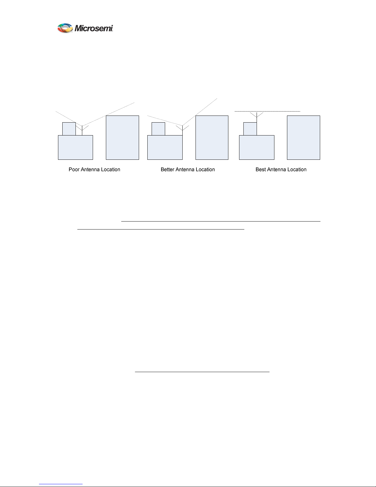
A. Placement of the GPS antenna is extremely important. It should be placed so that it has
clear view of as much sky as possible. Any obstructions such as antennas, large metal
objects, or buildings will limit the performance of the ATS-6501. The GPS antenna
should have an unobstructed line of sight to the sky. See Figure 1.
B. In selecting a location for the antenna, its proximity to the ATS-6501 should also be
considered. Ideally, the antenna will be close enough to the ATS-6501 so that there will
be a minimal loss through the antenna cable.
9
Page 18
100
ATS-6501 Users Guide
WARNING: An outside antenna system should not be located in the vicinity of
overhead power lines or other electric light or power circuits, or where it can fall into
such power lines or circuits. When installing an outside antenna system, extreme care
should be taken to keep from touching such power lines or circuits as contact with them
might be fatal.
Figure 1
C. Once a suitable antenna location has been identified, it is necessary to ensure that the
GPS signal that reaches the ATS-6501 is of suitable quality. The unit requires a
minimum of 15dB gain from the antenna gain combined with the amount of loss in the
antenna cable. The antenna included with the ATS-6501 has 25dB of gain so the total
cable losses in the system must not exceed 10 dB at 1.5 GHz. If you are using a different
antenna please ensure the antenna gain combined with the cable loss will provide
sufficient signal strength for the ATS-6501.
D. If the location of the antenna dictates that a longer cable must be used then a line
amplifier will need to be inserted into the signal path or you will need to run an antenna
cable with less loss. A line amplifier is a device used to amplify the GPS signal to
overcome the losses resulting from longer cable runs. In selecting a line amplifier it is
necessary to make sure that it provides an adequate amount of gain and that it operates
from 1200MHz to 1600MHz.
E. The amount of gain required from a line amplifier can be calculated by knowing the total
loss of the antenna cables being used. The signal loss due to a cable varies depending
upon the frequency of the signal. For the purposes of GPS antennas the cable loss should
be calculated at 1500MHz. The manufacturer of the cable being used should be able to
provide an estimate of the cable loss at 1500MHz. Once the cable loss is known it can be
inserted into Equation 2-1 to calculate the required gain of the line amplifier
)(_ −=
dBGainMIN
Antenna Location
DOC 6501_Release V
)(_*)100/(_
ftLengthCableftdBLossCable
Eq. 2-1.
12
F. The MIN_Gain value in Equation 2-1 serves as the minimum gain required from the line
amplifier being used. It is possible to use amplifiers with a slightly higher gain than the
minimum value but it will not improve the performance of the system. Using amplifiers
with significantly higher gain values can also cause degradation of the GPS signal
because it overdrives the input of the GPS receiver.
10
Page 19
DOC 6501_Release V
ATS-6501 Users Guide
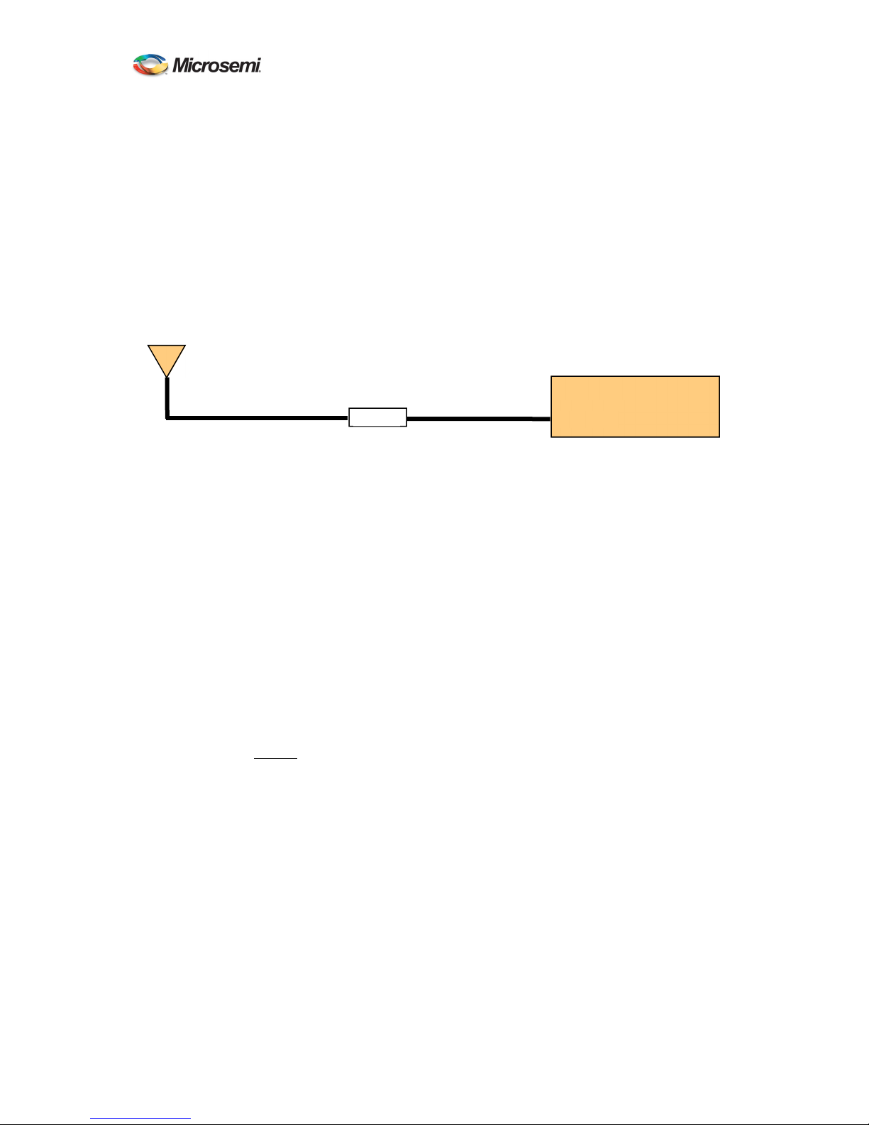
G. Placement of the line amplifier is also a concern in a properly designed system. Placing
the amplifier too far from the antenna may cause unexpected degradation in the GPS
signal and the performance will remain poor. The best place for the amplifier is typically
half way between the antenna and ATS-6501. This allows the line amplifier to benefit
from any surge protection that may be installed near the antenna but is still close enough
to the antenna so as not to degrade the signal significantly. Figure 2 shows the block
diagram of a typical installation that requires a longer antenna cable. Another
consideration when installing the line amplifier is how it will receive power. Some
amplifiers are powered using a DC bias on the antenna cable and others are power from
AC adapters directly. Please contact Microsemi if you require assistance in selecting the
right amplifier for your application.
ATS 6501
Line Amp
ANTENNA
Figure 2 Antenna Cable
The antenna mount should be secured to a stable structure such as a building, antenna
mast, or other suitable mounting platform.
H. The antenna is designed to withstand rain, snow, and dust. When selecting the mounting
location for the antenna try to find a location that will not become buried in snow and/or
covered by foliage. Keep the top surface of the antenna clean and brush off any ice and
snow, to ensure your antenna performs optimally. In addition, ensure the connector
remains clean and dry.
2.3.2 Setting the Antenna Voltage
The ATS-6501 is capable of providing antenna power (0, 5, 12VDC) by DC biasing the antenna
cable but this can cause damage to an antenna if the wrong voltage is applied. Prior to connecting
an antenna to the unit, ensure the antenna voltage is set properly. The ATS-6501 is shipped from
the factory with the default antenna voltage of 0 volts. If this is not the desired configuration then
follow the steps below to set the proper antenna voltage.
A. Telnet into the system command port telnet ip addr 1700 or connect via the USB Port and
the command prompt should appear.
B. At the command prompt, type settings gps and press enter, this will display the user
configurable GPS settings for the unit to see verify the current voltage being supplied to
the antenna
ATS-6501>settings gps
[antenna_delay] 2.277000000000000e-07
[antenna_voltage] 1.200000000000000e+01
[datum] wgs84
[mask_angle] 1.000000000000000e+01
11
Page 20

DOC 6501_Release V
ATS-6501 Users Guide
[positioning]
[auto_hours] 1.200000000000000e+01
[manual_position]
[altitude] 1.963225000000000e+02
[latitude] 3.992277661000000e+01
[longitude] -7.758567306000000e+01
[mode] auto
[tracking_timeout] 1800
[OK] 2013-08-05T14:28:57Z
C. To change the value, type antenna_voltage and the desired value (0, 5, or 12) and press
enter. The system should respond with “OK”.
ATS-6501>antenna_voltage 12
[OK] 2013-08-05T14:30:16Z
Note: If you enter an incorrect value you will get the following error message:
ATS-6501>antenna_voltage 3
Usage: antenna_voltage <0 | 5 | 12>
[ERROR] 2013-08-05T14:30:53Z
D. You can verify the setting is correct by typing settings gps:antenna_voltage and pressing
enter, this will display the updated user configurable settings.
0 VDC 0.0000000000000000e+00
5 VDC 5.0000000000000000e+00
12VDC 1.2000000000000000e+01
The antenna voltage setting can also be verified using a voltmeter. To verify the antenna
voltage, apply the probes to the ANTENNA connector on the rear panel. The center
conductor should be at a higher potential than the ATS-6501 chassis. This voltage
reading indicates the voltage being provided to the antenna. If no voltage is present then
the antenna is not being powered by the ATS-6501.
E. If this setting is correct type save to save the current user default configuration on the
system to ensure the system provides the proper antenna voltage after a reboot or power
cycle.
2.3.3 Outdoor Antenna Grounding
If an outside antenna is connected to the ATS-6501, be sure the antenna is grounded so as to
provide some protection against voltage surges and built-up static charges. Article 810 of the
National Electrical Code, ANSI/NFPA 70 provides information with regard to proper grounding
of the mast and supporting structure, grounding of the lead-in wire to an antenna discharge unit,
size of grounding connectors, location of antenna discharge unit, connection to grounding
electrodes, and requirements for the grounding electrode.
2.3.4 Antenna Mask Angle
Adjustment of the antenna mask angle may be necessary for installations with severe multi-path
problems. The mask angle of the antenna refers to the elevation angle above the horizon at which
all satellites above it are tracked. It may be possible to track satellites below the mask angle but
the data is intentionally omitted because it is unreliable. Installations with severe multi-path
12
Page 21

DOC 6501_Release V
ATS-6501 Users Guide
problems may find that they get better timing performance out of the ATS-6501 when using a
higher mask angle. To set the mask angle access the system via the command port and use the
mask_angle command to set the desired mask angle for the receiver. Mask angle value is in
degrees.
ATS-6501>mask_angle 10
[OK] 2013-08-05T15:05:12Z
You can verify the current value of the mask angle by sending the settings gps:mask_angle
command.
ATS-6501>settings gps:mask_angle
1.000000000000000e+01
[OK] 2013-08-05T15:04:43Z
If this setting is correct type save to save the current user default configuration on the system to
ensure the system uses the proper mask angle after a reboot or power cycle.
2.3.5 Positioning Modes
The ATS-6501 offers three different modes for determining the antenna position and determining
receiver operation, dynamic, auto, and manual.
2.3.5.1 Dynamic Position Mode
The Dynamic mode is typically used for systems located on mobile platforms.
Note: The system default mode is dynamic. Users at static locations should change this to auto
or manual based on the information provided below.
2.3.5.2 Auto Position Mode
The Auto mode is recommended for static locations where the antenna location has not been
surveyed. When using the Auto mode the ATS-6501 will automatically determine the location of
its antenna. It does this by averaging its calculated position solutions over a period specified by
the auto_hours parameter. The factory default for the position period is 12 hours. It is
recommended that the auto positioning period should be set to at least 4 hours. Once the
position_period expires the ATS-6501 will enter the fixed position mode (status
gps:position:fixed). Fixing the antenna position reduces the noise of the GPS measurements and
increases the frequency stability of the timing outputs.
To set the positioning mode to auto use the position_mode command on the command port.
ATS-6501>position_mode auto
[OK] 2013-08-05T15:26:06Z
To set the positioning period, use the position_period command. If not specified the value will be
in hours. Users can set this value to minutes using m after the value.
ATS-6501>position_period 12
[OK] 2013-08-05T15:26:06Z
13
Page 22

DOC 6501_Release V
ATS-6501 Users Guide
Select the proper datum (WGS84 (default) or NAD83) using the datum command.
ATS-6501>datum wgs84
[OK] 2013-08-05T15:28:14Z
To verify these use the settings gps command to check the current settings.
ATS-6501>settings gps
[antenna_delay] 2.650000000000000e-07
[antenna_voltage] 1.200000000000000e+01
[datum] wgs84
[mask_angle] 1.000000000000000e+01
[positioning]
[auto_hours] 1.200000000000000e+01
[manual_position]
[altitude] 1.963545000000000e+02
[latitude] 3.992275796000000e+01
[longitude] -7.758566956000000e+01
[mode] auto
[tracking_timeout] 1800
[OK] 2013-08-05T15:27:19Z
If these settings are correct type save to save the current user default configuration on the system
to ensure the system uses the positioning mode and period after a reboot or power cycle.
Note: If the unit is rebooted, power cycled, or the application is restarted with the positioning
mode set to auto, the system will go through the process of determining its antenna position based
on the position period (auto_hours). Once that period expires the system will again set itself
fixed and use the new determined solution as the fixed position. It will do this each time this
occurs. The [ptd] or UTC offset value reported by the system will be noisier during the auto
position period and will become significantly quieter when the antenna position is fixed.
In addition to automatically determining its antenna location, the ATS-6501 generates a RINEX
(Receiver INdependent EXchange) format observation file (not presently provided on the
SAASM Version). This file format is a standard used by the GPS community and provides all the
necessary GPS measurements for determining the antenna location. The file can be retrieved
from the system by using ftp (login: ftp, password: ftp) to log in and retrieve the file. The file
will be in the “rinex” subdirectory and will have a “.[yy]o” extension where [yy] represents the
last two digits of the current year. Many online processing centers are available (e.g.,
http://www.ngs.noaa.gov/OPUS, http://sopac.ucsd.edu/cgi-bin/SCOUT.cgi) and will process the
observation file free of charge. Doing this improves the position estimate of the antenna and is
recommended for precise time recovery. After this is complete it is possible to set the position
mode to manual using the coordinates provided by these services.
Note: The receiver has a countdown timer to show the amount of time left (position_period)
while in the auto positioning mode. Once this timer counts to zero the RINEX file will be
generated, the receivers position (status gps:position:fixed) will be true and the [time_remaining]
field will no longer be present in the status message.
ATS-6501>status gps:auto_positioning
[time_remaining] 10 hours, 51 minutes
14
Page 23

DOC 6501_Release V
ATS-6501 Users Guide
[OK] 2013-08-05T15:32:05Z
ATS-6501>status gps:position
[alt] 1.965699000000000e+02
[fixed] false
lat] 3.992275579961000e+01
[lon] -7.758567122127999e+01
[OK] 2013-08-05T15:32:33Z
2.3.5.3 Manual Position Mode
If the location of the antenna is known then the Manual mode should be used. This mode uses the
information provided by the datum, latitude, longitude, and altitude parameters to fix the antenna
position at startup.
Note: This bypasses the auto positioning period and the ATS-6501 will not generate a RINEX
observation file. This mode of operation is recommended ONLY if the antenna position is
known. Once you set any of these three parameters (lat, lon, or alt) the ATS-6501 will
automatically go into manual mode.
Caution: If the operator enters the manual position incorrectly the system will indicate it is
tracking satellites in the status output, however the system may show the gps status as “not
tracking” both in the status results and the front panel. To correct this problem ensure the
position is entered correctly, if this does not work, set the unit to the auto position mode and resurvey the antenna position.
ATS-6501>status gps:satellite:number
9
[OK] 2013-08-05T15:36:14Z
ATS-6501>status gps:mode:desc
tracking
[OK] 2013-08-05T15:37:27Z
To manually set the antenna position, use the following steps:
A. Select the proper datum (WGS84 (default) or NAD83) using the datum command.
ATS-6501>datum wgs84
[OK] 2013-08-05T15:42:42Z
B. Set the latitude for the antenna using the latitude command.
ATS-6501>latitude 38.46627893094
or
ATS-6501>latitude 38.46627893094N
Note: Default is [N]orth. If you are in the southern hemisphere make sure there is an
[S]outh after the latitude or a (-) before the latitude.
ATS-6501>latitude -38.46627893094
or
ATS-6501>latitude 38.46627893094S
15
Page 24

DOC 6501_Release V
ATS-6501 Users Guide
C. Set the longitude for the antenna using the longitude command.
ATS-6501>longitude 77.44086542274004
or
ATS-6501>longitude 77.44086542274004E
Note: Default is [E]ast. If you are in the Western hemisphere make sure there is an
[W]est after the latitude or a (-) before the latitude.
ATS-6501>longitude -77.44086542274004
or
ATS-6501>longitude 77.44086542274004W
D. Set the altitude for the antenna using the “altitude” command. Default value is ellipsoid
height meters. Users can specify the height in feet by using F after the value.
ATS-6501>altitude 51.573999999999998
or
ATS-6501>altitude 169.206037003 F
E. Verify the current settings are correct using the settings gps command or narrow it down
further with the settings gps:positioning:manual_position and settings gps:datum
commands.
ATS-6501>settings gps:positioning:manual_position
[altitude] 5.1573999999999998e+01
[latitude] 3.8466278930940000e+01
[longitude] -7.7440865422740004e+01
ATS-6501>settings gps:datum
wgs84
[OK] 2013-08-05T15:43:31Z
The operator also has the option of setting the manual mode and entering all three parameters on
the same command line using the fix_position (current | lat, lon, alt) command.
ATS-6501> fix_position 38.46627893094 -77.44086542274004 51.573999999999998
Warning: If the operator uses this command and does not provide any of the arguments the unit
will set its position based on the current system status (status gps:position) value. Doing this may
cause accuracy issues because of position errors.
If these settings are correct type save to save the current position on the system to ensure the
system uses the manual positioning mode after a reboot or power cycle.
2.4 ATS-6501 Installation
The ATS-6501 is ready for installation into a standard 19" (48.3 cm) rack using either slides or
shelves and will take up 1U of rack space. The C-300-S Series rack slides from General Devices
or equivalent slides are recommended.
CAUTION: Use the screws provided with the unit to mount the rails to the side of the chassis.
If longer screws are used, you could damage the power supplies or prevent them from being
removed from the chassis.
16
Page 25

ATS-6501 Users Guide
DOC 6501_Release V
2.4.1 Power Supplies
The ATS-6501 operates with two power supplies capable of operating on different power sources.
The 4385A (AC Power Supply) and 4386A (DC Power Supply) are available. The ATS-6501 is
capable of operating on one power supply in the event the other fails or its input source fails.
Power Supply #1 is on the left and Power Supply #2 is on the right. See Appendix A for the
specifications on the Power Supplies.
2.4.2 Input/Output Cards
The ATS-6501 will operate with five different types of output cards and one input card. The
cards can be operated in any of the six slots. The unit will automatically detect and configure the
system based on the card(s) installed. The card slots are identified by slot number so the operator
is capable of identifying the cards physical location in the chassis. The view below is from the
rear of the unit from left to right.
Slot 1 Slot 3 Slot 5
Slot 2 Slot 4 Slot 6
Figure 3
Each input/output card has four connectors with the port number identified as shown below in
Figure 4. See Appendix A for the specifications of each card.
Rear Panel Output Card Locations
Figure 4 Input/Output Cards
2.4.2.1 4394A (PPS/DC IRIG)
The factory default for this module provides two 1PPS outputs and two DC IRIG (B000) Outputs.
Outputs 1 and 2 are 1PPS and Outputs 3 and 4 are DC IRIG.
The output types are user selectable/programmable. Users can change the signal types (PPS/DC
IRIG), the PPS signal parameters, and the IRIG signal types on individual output ports.
• PPS: Valid PPS settings are 1, 10, 100, 1K, 10K, 100K, 1M, and 10M PPS. To set
the PPS signal parameters use the pps command:
ATS-6501> pps [slot#] [port#] [pulse period] [pulse width]
The following example sets the PPS on Slot 1, Port 2 to 1MPPS and the pulse width to
500 ns (1/2 the duty cycle).
ATS-6501>pps 1 2 1e-6 5e-7
17
Page 26

DOC 6501_Release V
ATS-6501 Users Guide
[OK] 2013-08-05T15:52:31Z
The following rules apply:
1. PERIOD - period of pulse in seconds(max of 1, min of 1e-7)
2. WIDTH - pulse width in seconds (minimum of 5e-8)
3. For PPS Rates where the duty cycle is 10 µs or greater the pulse_width must be a
multiple of 10 µs, at least 10 µs wide, and at most half the duty cycle of the
pulse_period.
4. For PPS rates where half the duty cycle is less than 10 µs, the pulse_width must be
exactly one-half the pulse_period. (See example above.)
The system will generate an error message if the values are not correct or entered
improperly.
Usage: <slot#> <port#> <pulse period> <pulse width>
[ERROR] 2013-08-05T15:53:07Z
To verify the settings use the settings hardware:slots:N command (where N=Slot #) to
obtain the current settings for a particular card.
ATS-6501> settings hardware:slots:1
[tsc4373]
[ports]
[1]
[pps_period] 1.000000000000000e+00
[pps_width] 1.000000000000000e-04
[type] pps
[2]
[pps_period] 1.000000000000000e+00
[pps_width] 5.000000000000000e-01
[type] pps
[3]
[format] A
[signal_word] 3
[type] irig
[4]
[format] B
[signal_word] 0
[type] irig
[OK] 2013-08-05T15:51:30Z
• IRIG: Valid DC IRIG Codes are A (000,003,007), B (000,003,007), D002, E002,
G002, and H002. Default is B000. To set the IRIG Code for the individual ports use the
irig command:
ATS-6501> irig [slot#] [port#] [Code A-H] [Code Format <NNN>]
The following example sets the IRIG for Slot 1, Port 3 to A 003.
ATS-6501>irig 1 3 A 003
[OK] 2013-08-05T16:02:16Z
18
Page 27

DOC 6501_Release V
ATS-6501 Users Guide
The system will generate an error message if the operator attempts to enter an
unsupported or invalid code.
To verify the settings use the settings hardware:slots:N command (where N=Slot #) to
obtain the current settings for a particular card.
ATS-6501> settings hardware:slots:1
[tsc4373]
[ports]
[1]
[pps_period] 1.000000000000000e+00
[pps_width] 1.000000000000000e-04
[type] pps
[2]
[pps_period] 1.000000000000000e-06
[pps_width] 5.000000000000000e-07
[type] pps
[3]
[format] A
[signal_word] 3
[type] irig
[4]
[format] B
[signal_word] 0
[type] irig
[OK] 2013-08-05T16:02:45Z
Note: The system will drop the leading Zeros in the signal_word.
To verify the card is working properly use the status hardware:outputs:slots:N command
(where N=Slot #) to obtain the current settings for a particular card.
ATS-6501>status hardware:outputs:slots:1
[ports]
[1]
[status] good
[2]
[status] good
[3]
[status] good
[4]
[status] good
[power] enabled
[type] 4394A
[OK] 2013-08-05T16:03:59Z
Warning: The user configuration for the specific output formats are stored on the
system itself. Replacement modules will automatically be configured with the correct
output format as long as the replacement card is installed in the same slot. Moving the
output module to a different slot causes the system to configure the module with the
default output format(s) until that card slot is properly configured by the user.
2.4.2.2 4376A RS-422 PPS
The factory default for this module provides four 1PPS outputs. Users can change the PPS signal
parameters, on individual signal outputs.
19
Page 28

DOC 6501_Release V
ATS-6501 Users Guide
Valid PPS settings are 1, 10, 100, 1K, 10K, 100K, and 1M PPS. To set the PPS signal parameters
use the pps command:
ATS-6501> pps [slot#] [port#] [pulse period] [pulse width]
The following example sets the PPS on Slot 1, Port 2 to 1MPPS and the pulse width to 500 ns
(1/2 the duty cycle).
ATS-6501>pps 1 2 1e-6 5e-7
[OK] 2013-08-05T15:52:31Z
The following rules apply:
1. PERIOD - period of pulse in seconds(max of 1, min of 1e-6)
2. WIDTH - pulse width in seconds (minimum of 5e-7)
3. For PPS Rates where the duty cycle is 10 µs or greater the pulse_width must be a
multiple of 10 µs, at least 10 µs wide, and at most half the duty cycle of the
pulse_period.
4. For PPS rates where half the duty cycle is less than 10 µs, the pulse_width must be
exactly one-half the pulse_period. (See example above.)
The system will generate an error message if the values are not correct or entered improperly.
Usage: <slot#> <port#> <pulse period> <pulse width>
[ERROR] 2013-08-05T15:53:07Z
To verify the settings use the settings hardware:slots:N command (where N=Slot #) to obtain the
current settings for a particular card.
ATS-6501>settings hardware:slots:5
[tsc4373]
[ports]
[1]
[pps_period] 1.000000000000000e+00
[pps_width] 1.000000000000000e-04
[type] pps
[2]
[pps_period] 1.000000000000000e+00
[pps_width] 1.000000000000000e-04
[type] pps
[3]
[format] B
[pps_period] 1.000000000000000e+00
[pps_width] 1.000000000000000e-04
[signal_word] 0
[type] pps
[4]
[format] B
[pps_period] 1.000000000000000e+00
[pps_width] 1.000000000000000e-04
[signal_word] 0
[type] pps
[OK] 2015-02-05T20:36:
20
Page 29

DOC 6501_Release V
ATS-6501 Users Guide
To verify the card is working properly use the status hardware:outputs:slots:N command (where
N=Slot #) to obtain the current settings for a particular card.
ATS-6501>status hardware:outputs:slots:5
[ports]
[1]
[status] good
[2]
[status] good
[3]
[status] good
[4]
[status] good
[power] enabled
[type] 4376A
[OK] 2015-02-05T20:27:05Z
2.4.2.3 4394A-ECL (PPS-ECL)
The factory default for this module provides two 1PPS outputs
The output types are user selectable/programmable. Users can change the PPS signal parameters.
Valid PPS settings are 1, 10, 100, 1K, 10K, 100K, and 1M PPS. To set the PPS signal parameters
use the pps command:
ATS-6501> pps [slot#] [port#] [pulse period] [pulse width]
The following example sets the PPS on Slot 1, Port 2 to 1PPS and the pulse width to 10us.
ATS-6501>pps 1 2 1 1e-5
[OK] 2013-08-05T15:52:31Z
The following rules apply:
1. PERIOD - period of pulse in seconds(max of 1, min of 1e-6)
2. WIDTH - pulse width in seconds (minimum of 5e-7)
3. For PPS Rates where the duty cycle is 10 µs or greater the pulse_width must be a
multiple of 10 µ s, at least 10 µ s wide, and at most half the duty cycle of the
pulse_period.
4. For PPS rates where half the duty cycle is less than 10 µs, the pulse_width must be
exactly one-half the pulse_period.
The system will generate an error message if the values are not correct or entered improperly.
Usage: <slot#> <port#> <pulse period> <pulse width>
[ERROR] 2013-08-05T15:53:07Z
To verify the settings use the settings hardware:slots:N command (where N=Slot #) to obtain the
current settings for a particular card.
ATS-6501> settings hardware:slots:1
[tsc4373]
[ports]
[1]
21
Page 30

DOC 6501_Release V
ATS-6501 Users Guide
[pps_period] 1.000000000000000e+00
[pps_width] 1.000000000000000e-04
[type] pps
[2]
[pps_period] 1.000000000000000e+00
[pps_width] 1.000000000000000e-05
[type] pps
[3]
[format] A
[signal_word] 3
[type] irig
[4]
[format] B
[signal_word] 0
[type] irig
[OK] 2013-08-05T15:51:30Z
To verify the settings use the status hardware:outputs:slots:N command (where N=Slot #) to
obtain the current settings for a particular card.
ATS-6501> status hardware:output:slots:1
[tsc4373]
[ports]
[1]
[status] good
[2]
[status] good
[3]
[status] n/a
[4]
[status] n/a
[power] enabled
[type] 4394A-ECL
[OK] 2013-08-05T15:51:30Z
Warning: The user configurations for the specific output formats are stored on the system itself.
Replacement modules will automatically be configured with the correct output format as long as
the replacement card is installed in the same slot. Moving the output module to a different slot
causes the system to configure the module with the default output format(s) until that card slot is
properly configured by the user.
2.4.2.4 4391 Code Generator
The 4391 Code Generator is capable of generating user defined bit streams with a known
relationship to UTC. The code generation segment uses the local UTC estimate and a usergenerated data file and produces a bit stream (derived from the user-generated file) whose first bit
is aligned to within 1 ns of the local UTC estimate.
The user must set up the card for the proper clock, memory block, port, and stream settings for
the system to operate within the end user environment. By default the output is a 4MHz square
wave. Ports 1 and 2 are 4V 0-pk into 50 and Ports 3 and 4 are 2.8V 0-pk into 50. All 4 ports
are in phase.
The outputs are user programmable based on the commands described below.
22
Page 31

DOC 6501_Release V
ATS-6501 Users Guide
List: This command allows users to obtain a list of bit files on the system. These files are
managed by the user. By default the system does not have any bit files. When checking to see if
there are any files use the bitcode_list command. If no files are available the system will report
this otherwise the operator will get a file listing.
ATS-6501>bitcode_list
No files found
ATS-6501>bitcode_list
Byte Size Name
--------- --- 125000 125k_hdrtrl.bin
1000000 1m_othdr.bin
1000000 1m_othdrtrl.bin
18 legacyhdrbe.bin
18 legacyhdrle.bin
The operator can also search using wildcards to obtain a more specific list of the files loaded onto
the system.
ATS-6501>bitcode_list 1m*
Byte Size Name
--------- --- 1000000 1m_othdr.bin
1000000 1m_othdrtrl.bin
[OK] 2014-05-01T12:10:14Z
The bitcode files are managed using FTP user=bitcode, password=bitcode. The ‘bitcode’ FTP
user’s home directory is /data/bitcode, which is the only area of the file system accessible to the
‘bitcode’ FTP user. Files in this directory may be selected for download to 4391A output cards
using the bitcode_memblock command. Files with an extension of “.txt” are treated as ASCII
formatted bitcode files unless otherwise specified by the operator. All other files shall be treated
as binary formatted bit code files unless otherwise specified by the operator. The Legacy format
supports the files used with the TSC-2152B.
Clock: This command configures one or both of the bit generator clocks on a 4391A output card.
Syntax
ATS-6501> bitcode_clock --bitrate BITRATE --delay DELAY --enable <1|0> SLOT [CLOCK]
o bitrate: Bit rate to which the specified bit generator clock is to be set. BITRATE must be
an integer between 1 and 8e6. Exponential notation is valid as long as the result is an
integer in the specified range. If not specified, the bit rate shall remain unchanged. If the
specified bit rate is not an integer between 1 and 8e6 the following error message shall be
displayed: “Bit rate must be an integer or an exponential that evaluates to an integer
between 1 and 8e6”
o delay: Number of seconds by which the specified bit generator clock is to be delayed
from the system on-time point. DELAY shall be treated as a signed floating point
number and must be between -0.5 and +0.5. If not specified, the delay shall remain
unchanged. If the specified delay is not a value between -0.5 and +0.5 the following error
message shall be displayed: “Delay must be a value between -0.5 and +0.5”
23
Page 32

DOC 6501_Release V
ATS-6501 Users Guide
o enable: Enable (true) or disable (false) the specified bit generator clock. If not specified,
the enable state shall remain unchanged. If the specified enable state is not “true” or
“false” the following error message shall be displayed: “Enable must be true or false”
o SLOT: Slot number of the 4391A output card for which a bit generator clock is to be
configured. SLOT must be an integer between 1 and 6.
o CLOCK: Bit generator clock number to which the command shall apply. CLOCK must
be 1 or 2. If not specified, the command shall apply to both clocks.
To set the Clock parameters use the bitcode_clock command and specify the bitrate (1 –
8000000), the delay (+/- 0.5 seconds), the slot # (1-6), and the clock number (1 or 2). Users can
enable/disable the clock using the --enable 0 (off) or 1 (on).
The following example sets the bitrate for clock 2 on Slot 5 to 4000000.
ATS-6501>bitcode_clock --bitrate 4000000 --delay 0 --enable 1 5 2
To verify the settings use the settings hardware:slots:N:tsc4391:clocks command (where N=Slot
#) to obtain the current clock settings for the 4391 card.
ATS-6501>settings hardware:slots:5:tsc4391:clocks
[1]
[bit_rate] 8000000
[delay] 0.000000000000000e+00
[enabled] true
[2]
[bit_rate] 4000000
[delay] 0.000000000000000e+00
[enabled] true
[OK] 2014-04-29T15:50:07Z
Memory Block: This command shall assign a memory block to one of the 4 8-megabit memory
blocks of a 4391A output card. The application software will manage the file I/O, download,
firmware validation, and retry (if necessary). To set the card parameters use the
bitcode_memblock command and specify the file (or no file), and the format, and the bitcount.
Enabling or disabling a port on a 4391A output card is a separate function from enabling or
disabling the bit generation on the 4391A card. When a port on a 4391A output card is disabled
or when all outputs are globally disabled, the output signal of the port is electrically isolated from
the bit generator output and is set to a constant zero value. When a port on a 4391A output card
is enabled, the output reflects the current value of the assigned data source. Bit generation is
enabled and disabled by enabling or disabling the code stream engines. When changing the
parameters of an enabled bit generator clock, the software shall disable the clock, make the
specified changes, and re-enable the clock when appropriate. Memory block download may
occur only if the block is not associated with enabled code generator stream.
Syntax
bitcode_memblock --file FILE --nofile --format <binary|ascii|legacy> --bitcount BITCOUNT SLOT BLOCK
24
Page 33

DOC 6501_Release V
ATS-6501 Users Guide
o file: Name of the bit code file to download to the specified memory block. If FILE is an
empty string the memory block shall be marked unused and all other option values shall
be ignored. If not specified and the --nofile option is not specified, the bit code file
assigned to the memory block shall remain unchanged. This option may not be specified
with the --nofile option.
o nofile: Marks the specified memory block as unused and causes all other option values to
be ignored. This option may not be specified with the --file option.
o format: Data format of the bit code file. If not specified and the --file and --nofile
options are not specified, the format shall remain unchanged. If not specified and the -file option is specified, the file name extension shall be used to determine the format.
o bitcount: Number of data bits to download to the specified memory block. If greater
than the number of data bits in the file, the data block shall be padded with zero bits. If
not specified and the --file and --nofile options are not specified, the bit count shall
remain unchanged. If not specified and the --file option is specified, the bit count shall be
set to the number of data bits in the file.
o SLOT: Slot number of the 4391A output card onto which the bit code file is to be
downloaded. SLOT must be an integer between 1 and 6.
o BLOCK: Memory block into which the bit code file is to be downloaded. BLOCK must
be an integer between 1 and 4.
Bit Code File Formats
• Binary Format: Binary format bit code files shall be treated as an array of data bits.
The data bits shall be ordered from the least significant bit of the first byte in the file to
the most significant bit of the final byte in the file.
• ASCII Format: ASCII format bit code files shall be treated as an array of 8-bit
characters. The character ‘0’ (ASCII 48, 0x30) shall be considered a data bit with value
zero. The character ‘1’ (ASCII 49, 0x31) shall be considered a data bit with value one.
All other characters shall be discarded. The data bits shall be ordered from the first byte
in the file to the last byte in the file, with discarded characters excluded. The application
software shall convert the data bits to a binary format before downloading the data to a
4391A output card.
• Legacy Format: Legacy format bit code files shall have the format emitted by the
‘tsc2152data’ data conversion program. Bytes 0 - 3 shall contain the magic number
0xdb24bd42 in little endian or big endian format. Bytes 4 - 7 shall contain the number of
bytes in the comment field, interpreted with the same endian format as the 4 bytes of the
magic number field. The data bits shall be ordered from the least significant bit of the
first byte after the comment field to the most significant bit of the final byte in the file.
The file header shall be removed before downloading the data to a 4391A output card.
• Data Truncation and Padding: An operator shall have the ability to truncate a
sequence of data bits at any point when downloading the data to a 4391A output card, and
25
Page 34

DOC 6501_Release V
ATS-6501 Users Guide
shall have the ability to pad a sequence of data bits with zero bits by specifying a bit
count larger than the number of data bits in the file.
The following example loads binary file with an 8,000,000 bit count to slot 5, block 1.
ATS-6501>bitcode_memblock --file 1m_othdrtrl.bin --format binary --bitcount 8000000 5 1
[OK] 2014-04-29T16:17:53Z
To verify the settings use the settings hardware:slots:5:tsc4391:memblocks command (where
N=Slot #) to obtain the current information on the memory blocks for the 4391 card.
ATS-6501>settings hardware:slots:5:tsc4391:memblocks
[1]
[bit_count] 8000000
[file_format] binary
[file_name] 1m_othdrtrl.bin
[2]
[bit_count] 0
[file_format] binary
[file_name]
[3]
[bit_count] 0
[file_format] binary
[file_name]
[4]
[bit_count] 0
[file_format] binary
[file_name]
[OK] 2014-04-29T23:18:13Z
Streams: This command shall configure one or more bit generator streams on a 4391A output
card.
To set the Stream parameters use the bitcode_stream command and specify the clock (1 | 2), the
data (block (memory block #) | square), the slot # (1-6), and a comma delimited stream list. Users
can enable/disable the stream using the --enable 0 (off) or 1 (on).
Syntax
ATS-6501> bitcode_stream --clock CLOCK --data <BLOCK|square> --enable <true|false> SLOT
[STREAMLIST]
o clock: Bit generator clock number to assign to the specified stream(s). CLOCK must be
1 or 2. If not specified the assigned clock number(s) shall remain unchanged.
o data: Data source to assign to the specified stream(s). If SOURCE is an integer between
1 and 4, the specified memory block shall be assigned as the data source. If SOURCE is
the text string “square”, the FPGA’s square wave generator shall be assigned as the data
source. If not specified, the assigned data source shall remain unchanged. If the
specified data source is not an integer between 1 and 4 or the text string “square” the
following error message shall be displayed: “Data must be ‘square’ or a block number
between 1 and 4”.
26
Page 35

DOC 6501_Release V
ATS-6501 Users Guide
o enable: Enable or disable the specified bit generator stream. If not specified, the enable
state shall remain unchanged. If the specified enable state is not “true” or “false” the
following error message shall be displayed: “Enable must be true or false”.
o SLOT: Slot number of the 4391A output card for which a bit generator clock is to be
configured. SLOT must be an integer between 1 and 6.
o STREAMLIST: Stream(s) to configure. STREAMLIST must be a comma-delimited list
of streams, each of which is an integer between 1 and 4. If not specified, the command
shall apply to all bit code streams on the 4391A output card. If only 1 stream is specified,
no comma is necessary. If the stream list is not a comma-delimited list of integers
between 1 and 4 the following error message shall be displayed: “Streamlist must be a
comma-delimited list of integers between 1 and 4”.
The following example sets streams 2 and 4 to clock 2 using data type square on slot 5.
ATS-6501>bitcode_stream --clock 2 --data square --enable 1 5 2,4
[OK] 2014-04-29T16:17:53Z
The following example has slot 5, stream 3 running on clock 1 and sending the data from memory
block 1.
ATS-6501>bitcode_stream --clock 1 --data 1 --enable true 5 3
[OK] 2014-04-29T23:23:58Z
To verify the settings use the settings hardware:slots:N:tsc4391:streams command (where
N=Slot #) to obtain the current streams settings for the 4391 card.
ATS-6501>settings hardware:slots:5:tsc4391:streams
[1]
[clock] 1
[data_source] square
[enabled] true
[memblock] 1
[2]
[clock] 2
[data_source] square
[enabled] true
[memblock] 2
[3]
[clock] 1
[data_source] memory
[enabled] true
[memblock] 1
[4]
[clock] 2
[data_source] square
[enabled] true
[memblock] 4
[OK] 2014-04-29T23:32:04Z
The following example turns slot 5 stream 3 off.
ATS-6501>bitcode_stream --enable false 5 3
27
Page 36

DOC 6501_Release V
ATS-6501 Users Guide
[OK] 2014-04-29T23:33:48Z
To verify the settings use the settings hardware:slots:N:tsc4391:streams:3 command (where
N=Slot #) to obtain the current streams settings for port 3 on the 4391 card.
ATS-6501>settings hardware:slots:5:tsc4391:streams:3
[clock] 1
[data_source] memory
[enabled] false
[memblock] 1
[OK] 2014-04-29T23:35:54Z
Port: This command shall configure one or more of the ports on the specified 4391A output
card.
To set the Port parameters use the bitcode_port command and specify the stream (1-4) and the
blanking type. Users can enable/disable the stream using the --enable false (off) or true (on).
Syntax
bitcode_port --stream STREAM --blanking <none|zeroes|ones> --enable <true|false> SLOT [PORTLIST]
o stream: Bit generation stream to assign to the specified port(s). If not specified, the
assigned stream shall remain unchanged. If the specified stream is not an integer between
1 and 4, the following error message shall be displayed: “Stream must be an integer
between 1 and 4”.
o blanking: Blanking mode for the specified port(s). Must be “none”, “zeroes”, or “ones”.
If not specified, the blanking mode shall remain unchanged. If not specified, the enable
state(s) shall remain unchanged. If the specified blanking mode is not “none”, “zeroes”,
or “ones”, the following error message shall be displayed: “Blanking must be ‘none’,
‘zeroes’, or ‘ones’”
o enable: Enables or disables the specified port(s). If disabled, an output is electrically
isolated from its associated bit generator output. If the specified enable state is not “true”
or “false” the following error message shall be displayed: “Enable must be true or false”
o SLOT: Slot number of the 4391A output card to be configured. SLOT must be an
integer between 1 and 6.
o PORTLIST: Port number(s) to configure. PORTLIST must be a comma-delimited list of
ports, each of which is an integer between 1 and 4. If not specified, the command shall
apply to all ports on the 4391A output card. If only 1 port is specified, no comma is
necessary. If the port list is not a comma-delimited list of integers between 1 and 4 the
following error message shall be displayed: “Port list must be a comma-delimited list of
integers between 1 and 4”
The following example assigns stream 3 to ports 1 and 3 on the card in slot 5.
ATS-6501>bitcode_port --stream 3 --blanking none --enable true 5 1,3
28
Page 37

DOC 6501_Release V
ATS-6501 Users Guide
[OK] 2014-04-29T23:44:47Z
To verify the settings use the settings hardware:slots:N:tsc4391:ports command (where N=Slot
#) to obtain the current streams settings for the 4391 card.
ATS-6501>settings hardware:slots:5:tsc4391:ports
[1]
[blanking] none
[enabled] true
[stream] 3
[2]
[blanking] none
[enabled] true
[stream] 2
[3]
[blanking] none
[enabled] true
[stream] 3
[4]
[blanking] none
[enabled] true
[stream] 4
[OK] 2014-04-29T23:45:58Z
2.4.2.5 4395A-10 / 4395B-10 10MHz Card
No programming is required for these modules. These modules will also work in any of the 6
card slots. To verify these cards are working properly use the status hardware:outputs:slots:N
command (N = slot number) to obtain the current status for a particular card.
ATS-6501>status hardware:outputs:slots:3
[ports]
[1]
[status] good
[2]
[status] good
[3]
[status] good
[4]
[status] good
[power] enabled
[type] 4395A-10
[OK] 2013-08-05T16:06:29Z
2.4.2.6 4395A-5 / 4395B-5 5MHz Card
No programming is required for these modules. These modules will also work in any of the 6
card slots. To verify these cards are working properly use the status hardware:outputs:slots:N
command (N = slot number) to obtain the current status for a particular card.
ATS-6501>status hardware:outputs:slots:4
[ports]
[1]
[status] good
[2]
[status] good
29
Page 38

DOC 6501_Release V
ATS-6501 Users Guide
[3]
[status] good
[4]
[status] good
[power] enabled
[type] 4395B-5
[OK] 2013-08-05T16:37:43Z
2.4.2.7 4395A-1 / 4395B-1 1MHz Card
No programming is required for these modules. These modules will also work in any of the 6
card slots. To verify these cards are working properly use the status hardware:outputs:slots:N
command (N = slot number) to obtain the current status for a particular card.
ATS-6501>status hardware:outputs:slots:5
[ports]
[1]
[status] good
[2]
[status] good
[3]
[status] good
[4]
[status] good
[power] enabled
[type] 4395B-1
[OK] 2013-08-05T16:37:43Z
2.4.2.8 4387A, 4387A-6V, and 4387A-1V (Modulated IRIG/NASA36)
This module provides four Amplitude Modulated (AM) IRIG Outputs or the NASA36 Serial
Time Code. Valid AM IRIG Codes are A (130, 133, 137), B (120, 123, 127), E (111, 112, 121),
G (141, 142, 147), and H (111, 112, 121, 122, 127). The default time code is B120. The 4387A6V module provides 6 Vpp output signals.
• IRIG: To set the IRIG Code for the individual ports use the irig command:
ATS-6501> irig [slot#] [port#] [Code A-H] [Code Format <NNN>] [epoch]
The following example sets the IRIG Code for Slot 5, Port 3 to G 141 and the epoch off
(epoch is off by default). The epoch option is not required to properly execute this
command and can be left off the command line.
ATS-6501>irig 5 3 G 141 0
OK
[OK] 2013-08-05T16:35:12Z
The system will generate an error message if the operator attempts to enter an
unsupported or invalid code.
To verify the settings use the settings hardware:slots:N command (where N=Slot #) to
obtain the current settings for a particular card.
ATS-6501>settings hardware:slots:5
[tsc4387]
30
Page 39

DOC 6501_Release V
ATS-6501 Users Guide
[ports]
[1]
[epoch_127] false
[format] B
[signal_word] 120
[type] irig
[2]
[epoch_127] false
[format] B
[signal_word] 120
[type] irig
[3]
[epoch_127] false
[format] G
[signal_word] 141
[type] irig
[4]
[epoch_127] false
[format] B
[signal_word] 120
[type] irig
[OK] 2013-08-05T16:40:12Z
• NASA36: To set the NASA 36 Code for the individual ports use the nasa36
command:
ATS-6501> nasa36 [slot#] [port#]
The following example sets the Time Code for Slot 5, Port 3 to NASA 36.
ATS-6501>nasa36 5 3
OK
[OK] 2013-08-05T16:41:25Z
The system will generate an error message if the operator attempts to enter an
unsupported or invalid code.
To verify the settings use the settings hardware:slots:N command (where N=Slot #) to
obtain the current settings for a particular card.
ATS-6501> settings hardware:slots:5
[tsc4387]
[ports]
[1]
[epoch_127] false
[format] B
[signal_word] 120
[type] irig
[2]
[epoch_127] false
[format] B
[signal_word] 120
[type] irig
[3]
[epoch_127] false
[format] B
[signal_word] 127
[type] nasa36
31
Page 40

DOC 6501_Release V
ATS-6501 Users Guide
[4]
[epoch_127] false
[format] B
[signal_word] 120
[type] irig
Warning: The user configuration for the specific output formats are stored on the system itself.
Replacement modules will automatically be configured with the correct output format as long as
the replacement card is installed in the same slot. Moving the output module to a different slot
causes the system to configure the module with the default output format(s) until that card slot is
properly configured by the user.
2.4.2.9 4396A/4397A 2MHz Output Card
No programming is required for these modules. These modules will also work in any of the 6
card slots. To verify these cards are working properly use the status hardware:outputs:slots:N
command (N = slot number) to obtain the current status for a particular card.
ATS-6501>status hardware:outputs:slots:3
[ports]
[1]
[status] good
[2]
[status] good
[3]
[status] good
[4]
[status] good
[power] enabled
[type] 4397A
[OK] 2013-08-05T16:06:29Z
2.4.2.10 4394A T1 (1.544MHz) Output Card
The 4374A module produces a 1.544 Mbps T1 (DS-1) compatible output. Each port can
independently be set to one of four output configuration options:
Mode 0: B8ZS, ESF packets (Default)
Mode 1: 1.544 MHz Square Wave
Mode 2: B8ZS, D4 packets, All 1's
Mode 3: B8ZS, D4 packets
In order to configure a specific output port format use the t1 command to specify the slot, port
and format.
Usage: t1 SLOT PORT MODE
SLOT slot number of card
PORT port number of output
MODE output mode number
Configuration of a specific output is stored on the system itself so that replacement modules will
automatically be configured with the correct output format. However, moving the output module
to a different slot causes the system to configure the module with the default output format until
reconfigured by the user.
32
Page 41

DOC 6501_Release V
ATS-6501 Users Guide
To verify the output card settings use the settings hardware:slots:N command where N is the slot
# where the 4374A card is installed.
ATS-6501>settings hardware:slots:3
[tsc4374]
[ports]
[1]
[enabled] true
[mode] 0
[2]
[enabled] true
[mode] 1
[3]
[enabled] true
[mode] 2
[4]
[enabled] true
[mode] 3
[OK] 2016-10-03T17:01:52Z
To verify these cards are working properly use the status hardware:outputs:slots:N command (N
= slot number) to obtain the current status for a particular card.
ATS-6501>status hardware:outputs:slots:3
[ports]
[1]
[status] good
[2]
[status] good
[3]
[status] good
[4]
[status] good
[power] enabled
[type] 4374A
[OK] 2016-10-03T16:57:24Z
2.4.2.11 4372A-T Fiber Output Card (Two-Way)
No programming is required for this module. This module will work in any of the 6 card slots.
To verify the card is working properly use the status hardware:outputs:slots:N command (N=Slot
#) to obtain the current status for a particular card.
ATS-6501>status hardware:outputs:slots:5
[comm_errors]
[4340A] 0
[6511]
[local] 0
[remote] 0
[ports]
[1]
[fiber_status]
[local_tdc] 1.541568627500000e-08
[packet_number] 2486
[remote_device] 6511
[serial_number] 163920
[input_status]
33
Page 42

DOC 6501_Release V
ATS-6501 Users Guide
[signal_detect] true
[tx_fault] false
[xcvr_present] true
[status] good
[2]
[fiber_status]
[local_tdc] 1.463137254900000e-08
[packet_number] 0
[remote_device] 6511
[serial_number] 163916
[input_status]
[signal_detect] true
[tx_fault] false
[xcvr_present] true
[status] good
[3]
[input_status]
[signal_detect] false
[tx_fault] false
[xcvr_present] true
[status] good
[4]
[fiber_status]
[local_tdc] 1.443529411800000e-08
[packet_number] 2
[remote_device] 6511
[serial_number] 154825
[input_status]
[signal_detect] true
[tx_fault] false
[xcvr_present] true
[status] good
[power] enabled
[type] 4372A-T
[OK] 2013-08-05T16:31:14Z
Note: Two-way over fiber is not supported prior to Version 4 of the software; if you are running
an earlier version of the software on the ATS-6501 and you install at 4372A-T card the system
will display an alarm condition. The hardware status will show the slot has a 4372A-T card
installed and the card has a “hardware error” and the downstream devices on that card will not be
able to sync to that fiber input.
2.4.2.12 4393A Time Interval Counter (TIC) Card
This module has four input ports that can be used to measure the time interval between the
internal 1PPS and up to four external sources and will work in any of the 6 card slots. The default
averaging period for the measurements is 10 seconds and can be adjusted using the ptdavg
command. Valid settings are 1, 10, 20, 60, 300 seconds. This setting is global and applies to all
of the TIC Cards installed in the ATS-6501.
ptdavg 20
OK
[OK] 2013-08-05T16:42:56Z
To verify the averaging interval use the settings ptd_port command
ATS-6501>settings ptd_port
[averaging_interval] 20
34
Page 43

DOC 6501_Release V
ATS-6501 Users Guide
[OK] 2013-08-05T16:49:56Z
To verify the card is working properly use the status hardware:outputs:slots:N command (N=Slot
#) to obtain the current status for a particular card.
ATS-6501>status hardware:outputs:slots:4
[ports]
[1]
[status] good
[2]
[status] good
[3]
[status] good
[4]
[status] good
[power] enabled
[type] 4393A
[OK] 2013-08-05T16:53:04Z
2.4.2.13 4383A IRIG Input Card
This module has four input ports that can be used to recover time from an IRIG time source.
Ports 1 and 2 support DC IRIG (Default B007) and Ports 3 and 4 support AM IRIG (Default
B127). By default Port #1 is active, to select another source or IRIG format use the irig_input
command. If the IRIG Source does not provide the year as part of the time code message (i.e.
B000/B120) the user can specify the year with the command.
ATS-6501>irig_input [slot#] [port#] [irig type] [year]
To verify the system settings use settings hardware:slots:N where N = the slot # where the card is
installed.
6501A_61>settings hardware:slots:6
[tsc4383]
[port]
[1]
[enabled] true
[format] B007
[2]
[enabled] false
[format] B007
[3]
[enabled] false
[format] B127
[4]
[enabled] false
[format] B127
To verify the card is working properly use the status hardware:outputs:slots:N command (N=Slot
#) to obtain the current status for a particular card. The selected IRIG Source will report as good,
the other ports will show as disabled.
6501A_61>status hardware:outputs:slots:6
[ports]
[1]
35
Page 44

DOC 6501_Release V
ATS-6501 Users Guide
[status] good
[2]
[status] disabled
[3]
[status] disabled
[4]
[status] disabled
[power] enabled
[type] 4383A
[OK] 2015-02-03T18:09:24Z
2.4.2.14 4337A Modulated IRIG with Epoch Support
This module provides four Amplitude Modulated (AM) IRIG Outputs tied to a user defined
epoch, UTC or GPS (default = UTC). Valid AM IRIG Codes are A (130, 133, 137), B (120, 123,
127), E (111, 112, 121), G (141, 142, 147), and H (111, 112, 121, 122, 127). The default time
code is B120.
• IRIG: To set the IRIG Code for the individual ports use the irig command:
ATS-6580> irig [slot#] [port#] [Code A-H] [Code Format <NNN>] [epoch]
The following example sets the IRIG Code for Slot 3, Port 3 to G 141 and the epoch to
UTC. The epoch option is not required to properly execute this command and can be left
off the command line.
ATS-6580>irig 3 3 G 141 utc
OK
[OK] 2013-08-05T16:35:12Z
The system will generate an error message if the operator attempts to enter an unsupported or
invalid code.
Note: The system currently supports the UTC or GPS Epochs. The IRIG Code and format can
vary by port however the system only supports one epoch per card. If the epoch is set to GPS the
card will output GPS Time (UTC – Current # of Leapseconds + 19).
To verify the settings use the settings hardware:slots:N command (where N=Slot #) to obtain the
current settings for a particular card.
ATS-6580>settings hardware:slots:3
[tsc4337]
[ports]
[1]
[epoch] gps
[format] B
[signal_word] 120
[type] irig
[2]
[epoch] gps
[format] B
[signal_word] 120
[type] irig
[3]
[epoch] gps
[format] G
[signal_word] 141
[type] irig
36
Page 45

=
ATS-6501 Users Guide
[4]
[epoch] gps
[format] B
[signal_word] 120
[type] irig
Warning: The user configuration for the specific output formats are stored on the system itself.
Replacement modules will automatically be configured with the correct output format as long as
the replacement card is installed in the same slot. Moving the output module to a different slot
causes the system to configure
DOC 6501_Release V
2.5 Antenna Delay Calibration
Utilizing the ATS-6501 as a precise time recovery system requires a complete calibration of the
ATS-6501 and distribution system. Cables and distribution equipment external to the ATS-6501
affect the calibration of the overall system and will result in an offset from UTC(USNO). This
section assumes the on-time-point (OTP) of the system is the rear panel outputs on the ATS-6501.
This may not be the desired location for the OTP; users should refer to section 2.6 for information
on changing the location of the OTP for the system.
For applications requiring the highest level of accuracy, the ATS-6501 should be calibrated at
Microsemi. This process involves installing the user’s antenna and antenna cable at the factory
and comparing the PPS outputs to a system which has a known offset to UTC(USNO). Once the
calibration is complete, the antenna delay value is provided to the customer when the unit is
delivered to the user. The PPS outputs will be accurate to the precise calibration levels specified
in Appendix A as long as the user installs the antenna at a surveyed location. If a surveyed
antenna location is not available, the ATS-6501 can be used to survey the location. See Section
2.3.5 on determining the antenna position.
A coarse calibration of the ATS-6501 is accomplished by accounting for the individual system
delays and combining them to determine the overall delay of the system. This method is
generally less accurate because the individual delays in the system are estimated and may not be
entirely accurate. Equation 2-2 gives the general formula for performing a coarse calibration of
the ATS-6501.
)(sec_ATS_6501
ondsDelay =
metersCableAntennaofLength
ondmetersVelocitySignal
The Signal_Velocity refers to the velocity of the GPS signal as it travels through the antenna
cable. This information can be obtained from the manufacturer of the cable. It is typically
specified as a percentage of the speed of light and it is up to the user to calculate the actual
Signal_Velocity. Calculation of the Signal_Velocity is shown in Equation 2-3. It is calculated
using the speed of light and the Velocity_of_Propagation given by the cable manufacturer. If the
Velocity_of_Propagation is not available or the accuracy of the PPS signal is not important to the
application then 0.85 may be used as a typical value.
Once the ATS-6501 delay has been calculated, it must be entered into the system using the
antenna_delay command. The example below is using a delay value of 118.5ns. Once the
)(___
)sec/(_
pagation_ProofVelocityondmetersVelocitySignal _*299792458)sec/(_
Eq. 2-3
Eq. 2-2
37
Page 46

Figure
5 Timing System Diagram
Delay 1 = Delay 2 = Delay 3 = Delay 4 =
DOC 6501_Release V
ATS-6501 Users Guide
antenna delay value has been properly set use the save command to save the current delay to
ensure the system uses the correct delay value after a reboot or power cycle. Users can verify the
value was set properly by using the settings gps:antenna_delay command and reviewing the
settings.
Note: The new delay value will take effect immediately and could cause an alarm if the delay
value forces the UTC(UNSO) offset to be larger than 100 ns. The system will steer the internal
clock to remove the antenna delay, if the alarm light came on it will go out once the UTC Value is
within 100 ns. The ATS-6501 outputs will now be accurate to the coarse calibration accuracy
specified in Appendix A.
ATS-6501>antenna_delay 1.185E-7
[OK] 2013-08-05T16:43:29Z
ATS-6501>settings gps:antenna_delay
1.185000000000000e-07
[OK] 2013-08-05T16:55:38Z
2.6 On Time Point (OTP)
The OTP of a system is defined as the point at which the timing signals coincide with
UTC(USNO). Typical systems use distribution amplifiers and cabling to distribute timing signals
from a single source to multiple users. This distribution network will delay the timing signals and
affect their accuracy. For this reason it is important to select an appropriate OTP so that the
desired timing signals are accurate when they reach the user.
This section describes calibration of the ATS-6501 assuming that the OTP of the system is the
rear panel of the ATS-6501. This is not generally a convenient location for the OTP of the
system because there will be a delay associated with the distribution of the signals to the user.
Figure 5 illustrates how to move the OTP of the system from the rear panel of the ATS-6501 to
the user inputs. In moving the OTP of the system it is imperative that the distribution delays from
the ATS-6501 to each of the users is equal. This will ensure that all users receive accurate timing
signals.
ATS 6501
PPS Output 1
PPS Output 2
PPS Output 3
PPS Output 4
Once the delay of the distribution network is known the OTP of the system can be shifted from
the output of the ATS-6501 to the input of user equipment. Equation 2-4 is used to calculate the
antenna_delay value that should be entered into the system to adjust the OTP. The
Distribution_Delay is the measured delay of the timing distribution network as shown in Figure
5. The ATS_6501_Delay is the delay calculated in Equation 2-2 or the calibrated delay given by
Microsemi.
OLD OTP
Delay 1
Delay 2
Delay 3
Delay 4
NEW OTP
User 1
User 2
User 3
User 4
Distribution_Delay
38
Page 47

+
=
DOC 6501_Release V
ATS-6501 Users Guide
(seconds)_(seconds)ATS6501_LAYANTENNA_DE DelayonDistributiDelay
Eq. 2-4
2.7 Using an External Frequency Reference
Users may decide to provide an EXTERNAL frequency reference to the ATS-6501. The external
frequency reference may be monitored by the ATS-6501 via a RS232 connection through either
of the USB Connectors on the rear of the unit (94001-5071A). The Microsemi 5071A is currently
the only model supported; users should contact Microsemi about the possibility of utilizing other
clocks. The 5071A communications settings on the 5071A must be set to 9600 Baud, No Parity,
8 Data Bits, and 1 Stop Bit (9600,N,8,1) and a null modem serial cable will be required.
WARNING: Prior to setting the reference to external ensure the 10MHz signal from the
reference is connected to the 10MHz IN connector on the rear of the ATS-6501. If not, the ATS6501 outputs may not remain within specifications and it could take up to several hours for the
system to begin providing outputs within their specifications.
ATS-6501
10 MHz In
USB
USB
To
Serial
10 MHz
Null Modem
Cable
Port 1/2
RS-232
(DTE)
5071
External reference
Figure 6 External Frequency Reference
Current status can be determined using the status reference:frequency:external command.
ATS-6501>status reference:frequency:external
[communications] N/A
[locked] true
[signal] present
[OK] 2013-08-05T17:17:08Z
signal missing 10MHz reference signal is not present. Do NOT select the reference
type as External.
cannot communicate 10MHz reference signal is present but the system is unable to
communicate with the 5071A
locked 10MHz reference signal is present and the system is able to
communicate with the 5071A
not monitored 10MHz reference signal is present. The system will not attempt to
communicate with the external reference.
2.7.1 Reference Type
The ATS-6501 is capable of using the following references:
• Cesium
• High Performance 5071A (hp5071a)
• Maser
To set the type of reference use the reference_type command and enter the correct clock type,
once complete type save to save the settings. The reference type should be set up based on the
type of clock and if you plan to monitor the h5701a.
39
Page 48

DOC 6501_Release V
ATS-6501 Users Guide
2.7.2 hp5071A Communications
If users are operating with a High Performance 5071A they can set the system up so the ATS6501 is communicating with (monitoring) the 5071A select hp5071a (default)
ATS-6501>reference_type hp5071a
[OK] 2013-08-05T16:51:17Z
Note: Make sure the USB-to-Serial Converter (94001-5071A) is installed on one of the two USB
ports when the system is powered on (See Figure 6). If not, power the system down, plug the
cable in and re-apply power. The USB/Serial Cables are programmed to communicate with an
external reference (ATS 94000-115200) or to provide users access to the command port (94000-
115200). These cables are NOT interchangeable.
Caution: If the system is unable to communicate with the external reference and the
reference_type is hp5071A the Alarm light will come on and the Osc Lock light will go out and
remain this way after you switch to the external reference. Make sure you select the proper
reference_type before switching to external.
2.7.3 Unmonitored Clocks
If users are operating with a High Performance 5071A or maser and they are not monitoring the
hp5071a set the reference_type to cesium or maser respectively.
ATS-6501>reference_type cesium maser
[OK] 2013-08-05T16:51:17Z
2.7.4 Selecting the External Reference
Use the status reference:frequency:external command and verify the signal is present and locked
= true before switching to the external reference.
6501A_60>status reference:frequency:external
[communications] N/A (Good if monitored, See 2.7.2)
[locked] true
[signal] present
[OK] 2016-10-04T20:58:09Z
To set the reference to external use the reference command via the command port.
ATS-6501>reference external
[OK] 2013-08-05T17:19:32Z
Note: The Alarm light will come on and the Osc Lock light will go out for a few seconds when
you switch references. The system should clear all alarm indications within a few seconds.
To verify the settings use the settings reference command to check the current settings.
ATS-6501>settings reference
[external]
[type] hp5071A cesium maser
[source] internal
40
Page 49

DOC 6501_Release V
ATS-6501 Users Guide
[steering]
[source] gps
[timescale]
[kas2]
[avgfiltermax] 0
[tsepoch] 0
[tsfiltermax] 2
[tsfilterref] N/A
[tsinterval] 3600
[tstimeconstant] 10800
[OK] 2013-08-05T17:22:04Z
If these settings are correct type save to save the proper reference and reference type in the default
user configuration file on the system to ensure the system starts up properly after a reboot or
power cycle.
Caution: Users should allow the external frequency reference to free run and should not
manually enter corrections/adjustments into the clock. The ATS-6501 characterizes the clock’s
frequency relative to GPS and manual/user adjustment of the clock frequency may cause the
ATS-6501 outputs to not meet specification following the adjustment.
WARNING: After replacing an external frequency reference, the restart --cold command must
be executed on the ATS-6501 by the operator to reset the KAS2 steering algorithm. If not, the
ATS-6501 outputs may not remain within specifications and it could take up to 9 days for the
system to provide outputs within specifications.
2.8 Using the Time Scale Reference
The timescale function can be used if a 4393 module is available and 2 or more clock’s 1 PPS
signals are input to the module. When timescale is selected the system uses the ensemble of
clocks plugged into the 4393 1 PPS measurement module as the frequency reference enhancing
timing performance and system redundancy. Clocks must be added via the 'add_clock' command
and the timescale filter reference must be set before the timescale will function.
The time scale reference setting utilizes the 1 PPS measurements from the 4393 module to create
an internal coordinated time scale (CTS) which steers the OCXO to the ensemble of clocks
connected to the 4393 module. The CTS is then steered to UTC to utilize the long term stability
of GPS. To set up the system to use the time scale as the reference, operators will need at least
two clocks to participate in the ensemble. Settings nodes are added by the user to represent each
clock in the ensemble using the add_clock command. These nodes are organized by a unique
name that is chosen by the user. The operator will have to specify the clock type which
determines most of the physical characteristics of the clock (the noise spectral densities, etc.), the
module slot and port number, and the clock status communication protocol if monitoring is
available. For instance, possible clock types might include “hp5071” and “maser”.
At a minimum adding a clock requires selection of the name, the clock type, and the module Slot
# and Port #to which the clock’s 1 PPS is connected.
add_clock Test1 --type cesium --slot 4 --port 1
add_clock Test2 --type cesium --slot 4 --port 1
Users can specify a formal identification string which is typically the clocks serial number.
41
Page 50

DOC 6501_Release V
ATS-6501 Users Guide
If the ATS-6501 is able to communicate with the clock for monitoring (i.e. type=hp5071A) the
operator will provide the communications method (serial | ip) and the physical address of the
clock (/dev/xxx) or (XXX.XXX.XXX.XXX:PORT#). Ethernet monitoring of the clock is
provided to enable use of a clock as a reference for multiple ATS 6501s. An external serial to
Ethernet converter must be used to utilize this feature. Each clock set up for monitoring will be
periodically polled to ensure the clock is functioning properly while operating with the ATS-
6501. No steering of the external clock is performed by the ATS-6501.
The next step in setting up the system is to select one of the clocks entered using the add_clock
command to be the reference for the filter by using the timescale_filterref command
timescale_filterref Test1
Example Settings for Type Cesium:
ATS-6501>settings reference:timescale
[clocks]
[Test1]
[comm]
[comm_addr] N/A
[comm_type] N/A
[id] 1365
[kas2]
[filter_member] true
[local] true
[sbeta] 2.000000000000000e-11
[smu] 1.950000000000000e+01
[sxi] 3.650000000000000e+01
[szeta] 0.000000000000000e+00
[weight_member] true
[weight_type] 0
[port] 1
[slot] 4
[type] cesium
[Test2]
[comm]
[comm_addr] N/A
[comm_type] N/A
[id] 0001
[kas2]
[filter_member] true
[local] true
[sbeta] 2.000000000000000e-11
[smu] 1.950000000000000e+01
[sxi] 3.650000000000000e+01
[szeta] 0.000000000000000e+00
[weight_member] true
[weight_type] 0
[port] 2
[slot] 4
[type] cesium
[kas2]
[avgfiltermax] 0
[tsepoch] 0
[tsfiltermax] 2
[tsfilterref] Test1
[tsinterval] 900
42
Page 51

DOC 6501_Release V
ATS-6501 Users Guide
[tstimeconstant] 900
[OK] 2013-09-04T23:40:15Z
Example Settings for Type hp5071A:
ATS-6501>settings reference:timescale
[clocks]
[Test1]
[comm]
[comm_addr] 192.168.150.103:10003
[comm_type] ip
[id] 1365
[kas2]
[filter_member] true
[local] true
[sbeta] 2.000000000000000e-11
[smu] 1.950000000000000e+01
[sxi] 3.650000000000000e+01
[szeta] 0.000000000000000e+00
[weight_member] true
[weight_type] 0
[port] 1
[slot] 4
[type] hp5071a
[Test2]
[comm]
[comm_addr] 192.168.150.104:10004
[comm_type] ip
[id] 0001
[kas2]
[filter_member] true
[local] true
[sbeta] 2.000000000000000e-11
[smu] 1.950000000000000e+01
[sxi] 3.650000000000000e+01
[szeta] 0.000000000000000e+00
[weight_member] true
[weight_type] 0
[port] 2
[slot] 4
[type] hp5071a
[kas2]
[avgfiltermax] 0
[tsepoch] 0
[tsfiltermax] 2
[tsfilterref] Test1
[tsinterval] 900
[tstimeconstant] 900
[OK] 2013-09-04T23:41:41Z
Setting the operating mode to timescale is accomplished using the reference command.
reference timescale
Operators can change clock configurations and edit clock settings using the config_clock and
edit_clock commands (refer to Appendix D for command details). Operators can also remove a
clock from the time scale using the remove_clock command.
43
Page 52

DOC 6501_Release V
ATS-6501 Users Guide
Warning: The noise parameters for each clock type are set up at the factory for best
performance. Any adjustments to these values must be performed by knowledgeable users as
changes can cause serious performance degradation.
Operators can check the status of the time scale using the settings reference:source and status
reference:frequency:timescale command.
ATS-6501>settings reference:source
timescale
[OK] 2013-09-04T23:56:46Z
Example Status for Type Cesium:
ATS-6501>status reference:frequency:timescale
[clocks]
[Test1]
[1_pps_present_slot_4_port_1] true
[communications] N/A
[id] 1365
[Test2]
[1_pps_present_slot_4_port_2] true
[communications] N/A
[id] 0001
[OK] 2013-09-04T23:54:37Z
Example Status for Type hp5071a:
ATS-6501>status reference:frequency:timescale
[clocks]
[Test1]
[1_pps_present_slot_4_port_1] true
[communications] good
[device_status]
[can_communicate] true
[electron_multiplier_voltage] 1.219000000000000e+03
[locked] true
[osc_freq_control] -3.500000000000000e-02
[power] AC
[serial_number] 3839A00621(S)
[signal_gain] 1.440000000000000e-01
[id] 1365
[Test2]
[1_pps_present_slot_4_port_2] true
[communications] good
[device_status]
[can_communicate] true
[electron_multiplier_voltage] 1.144000000000000e+03
[locked] true
[osc_freq_control] -1.413000000000000e-01
[power] AC
[serial_number] US38390769(S)
[signal_gain] 1.440000000000000e-01
[id] 0001
[OK] 2013-09-04T23:53:13Z
After the unit is set up in time scale, it will take a few hours for the steering to stabilize to where
the phase reported by status kas2 is less than a few ns. It is recommended that the unit is allowed
44
Page 53

DOC 6501_Release V
ATS-6501 Users Guide
to operate in timescale setting for at least 48 hours before changing the timescale steer interval or
time constant settings to longer times. The time constant can be increased by a factor of 10 every
48 hours until the time constant is 250000 using the timescale_steer_timeconstant command.
2.9 Setting the System Time Manually
The ATS-6501 is capable of operating without the GPS Receiver and maintains system time
through several methods
2.9.1 Force Time
The force_time command has several options and users have the flexibility of choosing the
method(s) that will work best based on installation and system architecture. Once the command
has been successfully completed NTP will lock to the new system time and the unit will enable
the outputs.
force_time default - snaps time to 01/01/2012 00:00:00.
force_time now - snaps time to the operating system's time, if possible.
force_time irig [year] - snaps time to the active irig input.
force_time <date-time> - snaps time to the specified time.
force_time <NTP server>- snaps time to that of a remote NTP server.
• Default – Sets the system time to 01 Jan 2012 00:00:00
• Now – Sets the system time to the operating systems time.
• IRIG – The system obtains the time from an IRIG Time source and sets the system time.
If the time code selected from the irig_input command does not provide the year the user
must specify the year on the command line.
• Date-Time – Allows the user to specify the date and time in the yyyy-mm-dd-hh:mm:ss
format
• NTP Server – The system obtains the time from an NTP Server and sets the system time.
Enter the IP address of the remote NTP Server.
If for any reason the system is unable to successfully set the system time it will report an error.
Note: The force_time command will not work unless the steer_source is set to manual.
2.9.2 Deterministic Phase Lock Loop (DPLL)
The ATS-6501 can recover time as well as align to an external source without having to use GPS.
The system time can be set manually or via an NTP Server. The Low Noise Synthesizer (LNS) in
system has the ability to have a deterministic phase acquisition to the LNS, to any 10 MHz
reference signal. The phase of the 10 MHz LNS output has a deterministic (nonzero, but the
same every time) phase relationship to the phase of the 10 MHz frequency reference, either the
internal Rb or external 10 MHz reference after the LNS PLL acquisition.
At a system level, this allows the ATS-6501 to use the 10 MHz external reference as the phase
reference for the system. The LNS makes phase measurements at a higher rate and with lower
noise against the 10 MHz reference input than it would otherwise be capable of doing with the
4393A Card (PPS TIC).
1. Set the ATS 6501 up as shown below:
45
Page 54

DOC 6501_Release V
ATS-6501 Users Guide
2. Using the TIC, measure the delay on the 1PPS cable between the Reference 1PPS and
4393A Card.
3. Measure the delay on the T-Flex TIC card input using a cable with a known delay and
connecting Slot 1 Port 1 (PPS Out) on the ATS-6501 to the TIC card (ex. 4393A) input.
Connect to Port 2101 and record the delay for that channel. Value should be in the low
nanoseconds.
TIC Card Delay = Port 2101 Value – Cable Delay = ____________________ns
4. Set the ATS-6501 up:
dpll_phase 0
steer_source manual
reference_type clock type
reference external
save
5. Power Cycle the ATS-6501.
a. Let the Osc Lock light come on.
b. Telnet to the ATS-6501 command port (1700).
c. Use the force_time command to set the system time.
d. Let the Outputs Enable light come on before proceeding.
6. Connect to Port 2101 and look at the measurement for the 1PPS Offset, use that value to
remove the offset. The offset should be larger than 100nSec. Smaller increments will be
ignored.
adjust_pps <value reported on port 2101>
7. Check the TIC Counter and use the value reported to set the dpll_phase value. This value
should be the inverse of the value reported on the TIC.
dpll_phase <TIC Value * (-1)>
save
46
Page 55

DOC 6501_Release V
ATS-6501 Users Guide
8. Create a node.cfg file in ‘/mod/tsc/site/’ to allow the ATS-6501 to use the TIC
measurement to set the PPS offset while using dpll. Make sure to su before editing this
file.
a. Set the
Example
-- node.cfg
-- This file was auto-generated by alarmserver sitecfgdb
---------------------------------------------------------------------------
-- dofile("/usr/tsc/site/node_types.lua")
-- Map the only numeric type that Lua understands, double, to integer where
-- necessary
ValueTreeTypes = {}
ValueTreeTypes.NodeId = "integer"
ValueTreeTypes.NodeType = "integer"
ValueTreeTypes.PollRate = {}
ValueTreeTypes.PollRate.Alarm = "integer"
ValueTreeTypes.PollRate.State = "integer"
ValueTreeTypes.PollRate.Inventory = "integer"
ValueTreeTypes.PortNumber = "integer"
ValueTreeTypes.ProtocolVersion = "integer"
Config = {}
Config.Self = {}
Config.Self.ProtocolVersion = 1
Config.Self.NodeId = 10
Config.Self.NodeType = 3
Config.Self.PollRate = {}
Config.Self.PollRate.Alarm = 30
Config.Self.PollRate.State = 30
Config.Self.PollRate.Inventory = 120
Config.Parents = {}
Config.Children = {}
Config.Measurement = {}
Config.Measurement[0] = {}
Config.Measurement[0].Name = "tic1"
Config.Measurement[0].Type = "Time"
Config.Measurement[0].Timescale = "UTC"
Config.Measurement[0].NodeId = 1
Config.Measurement[0].StreamId = 5
Config.Measurement[0].Resolution = 0.00
Config.Measurement[0].Deviation = 0.00
Config.Measurement[0].PhaseOffset = -3.1e-09 (TIC Channel Offset)
Config.Measurement[0].SendToSteering = true
Config.Measurement[0].SendToSmop = true
Config.Measurement[0].Source = {}
Config.Measurement[0].Source.Name = "Tsc4393"
Config.Measurement[0].Source.Slot = 4
Config.Measurement[0].Source.Port = 1
Config.Measurement[0].Timeout = 10
9. Verify the PPS alignment at startup:
a. Power Cycle the ATS-6501
b. Wait for the OSC Lock Light to come on
c. Connect to the command port (1700)
d. Set the steer_source to manual.
e. Use the force_time command and set the system time
f. Wait for the Outputs Enable light to come on.
PhaseOffset Value
in the node.cfg file to the TIC Card delay.
47
Page 56

DOC 6501_Release V
ATS-6501 Users Guide
g. Use the steer_source command to set steering to the value set in
Config.Measurement[0].Name = "tic1"
steer_source tic1
h. After ~15 minutes seconds the 1PPS on the TIC should read 0 +/- 150ps.
Note: This will be faster or slower depending on the reference clock type set in step 3
i. Check the 10MHz alignment on the scope and measure the offset between the two
inputs.
It is recommended to perform Step 9 each time the unit is restarted. Users will need to switch to
manual, set the time, and then switch back to the selected steer source.,
2.9.3 External Reference
When setting the time manually it is recommended users provide a 1PPS and 10MHz. Users can
select the proper clock type for the 10MHz input using the reference_type command and then
switching to reference external when the system is properly set up. Users will need to edit the
node.cfg (mod/tsc/site) file to use one or more 1PPS references from the 4393A TIC Card an
IRIG input from the 4383A IRIG Input Card as a steer source. (See Appendix F).
2.9.4 Disable the GPS Tracking Alarms
When using the system with manual time recovery users can set the system up to ignore the GPS
Tracking Alarms normally set when the system is not tracking GPS. This can be done by setting
the timeout to ZERO.
ATS-6501> gps_tracking_timeout 0
To confirm the system settings use the settings gps:tracking_timeout command.
6501A_61>settings gps:tracking_timeout
0
[OK] 2015-02-03T19:11:19Z
Warning: Setting the timeout to zero is only recommended with time sources other than GPS.
This setting will inhibit the GPS Tracking alarm even if the unit is using GPS as the time source.
2.10 User Configuration Files
The ATS-6501 provides the flexibility of operating using different user configurations. Users are
able to save these configurations for system settings and ftp | real-time data logging and recall
them when needed via the command port.
2.10.1 Factory / Default User Configuration Files
The ATS-6501 will boot up with the FACTORY configuration settings automatically and will
continue to use these settings until any changes to the configuration are made and saved as the
user default settings (default). To save the user default file simply type save and press enter.
This will save the updated configuration and the ATS-6501 will boot up (either from power on or
after a reboot/restart command) using the settings in the user default file. To see if the user
settings have been saved use the list command to obtain a list of the possible user configuration
files. If there are no user configuration files available the system will report no files.
48
Page 57

DOC 6501_Release V
ATS-6501 Users Guide
ATS-6501>list ATS-6501>list
default or no files
Note: The user default file is used at start up if it is present otherwise the unit will start up with
the factory default file. Users are encouraged to set AND save their default system settings based
on their application so the system will start up properly when powered up or after a reboot or
restart.
Users can create other configuration files. Simply make the desired changes to the system
configuration, type save and a filename to identify the configuration and press enter. The system
will save this configuration containing the new settings. To use this configuration file use the list
command to bring up a list of the possible configuration files and use the load command to have
the system load and start running with the desired user configuration settings. Use the settings
command to ensure the system is using the desired settings based on the newly loaded
configuration file.
ATS-6501>save example
[OK] 2013-08-05T17:22:04Z
ATS-6501>list
example
default
[OK] 2013-08-05T17:23:34Z
ATS-6501>load example
[OK] 2013-08-05T17:24:27Z
Note: The ATS-6501 will recognize case sensitive alphanumeric characters, -, ‘ ‘, and _. If any
other characters are used the system will inform the user that the filename is not valid and will not
save the settings.
ATS-6501>save te%^$st
Illegal Filename
[ERROR] 2013-08-05T17:29:17Z
Users can also remove any configuration files that are no longer needed on the system. Use the
list command to bring up a list of the available configuration files and use the delete <filename>
command to remove the desired file. Users must provide the filename of the file to be removed
from the system, if not the system will provide an error message reminding the user to identify
the file to be removed.
ATS-6501>delete example
OK
[OK] 2013-08-05T17:19:48Z
ATS-6501>delete
FILENAME
FILENAME Name of file
[ERROR] 2013-08-05T17:19:59Z
49
Page 58

DOC 6501_Release V
ATS-6501 Users Guide
Caution: Users can delete the user default file. If this is done and a new user default
configuration file is not saved, the system will use the factory defaults when rebooted, restarted,
or power cycled.
2.10.2 Diff Command
The ATS-6501 will track changes to the system settings that have been made and have not been
saved. Use the diff command to provide a complete list of settings that have been modified but
not saved. In the example below the ptdavg has been changed to 20 seconds but not saved. The
system will report the current setting and the saved (original) setting in the report.
ATS-6501>ptdavg 20
[OK] 2013-08-05T17:41:39Z
ATS-6501>diff
[current]
[ptd_port]
[averaging_interval] 20
[original]
[ptd_port]
[averaging_interval] 10
[OK] 2013-08-05T17:41:53Z
2.10.3 FTP and Real-Time (rt) Configuration Files
The ATS-6501 will boot up with the FACTORY ftp | rt log file settings automatically and will
continue to use these settings until any changes to the gps logging functions are made and saved
as the user default log settings (default). This will save the updated logging configuration and the
ATS-6501 will use these settings each time the system is power cycled, rebooted, or restarted. To
save the default log file settings simply type save_logs ftp or save_logs rt. To see if the user
settings have been saved use the list_logs ftp or list_logs rt command to obtain a list of the
possible configuration files. If there are no user configuration files available the system will
report no files.
ATS-6501>list_logs ftp ATS-6501>list_logs rt
default default
or if there are no log settings files,
ATS-6501>list_logs ftp
no files
Note: The ftp | rt user default files are used at start up if they are available otherwise the system
will use the factory default settings. To modify the ftp or real-time logging behavior, make the
changes needed based on your application and type save_logs ftp or save_logs rt. Users are
encouraged to set the user default ftp |rt settings based on their application so the system will
properly configure the logging after a reboot or power cycle.
Users can create other logging configuration files. Simply make the desired changes to the
logging configuration, type save_logs ftp or save_logs rt and a filename to identify the
configuration and press enter. The system will save this configuration containing the new
settings. To use this log configuration use the list_logs ftp or list_logs rt command to bring up a
list of the possible configuration files and use the load_logs ftp or load_logs rt command to have
the system load and start running with the desired configuration settings. Use the settings
50
Page 59

DOC 6501_Release V
ATS-6501 Users Guide
command to ensure the system is using the desired settings based on the newly loaded logging
configuration file.
ATS-6501>save_logs ftp example
[OK] 2010-05-25T17:32:27Z
ATS-6501>list_logs ftp
(working)
example
default
[OK] 2013-08-05T18:31:43Z
ATS-6501>load_logs ftp example
[OK] 2013-08-05T18:31:43Z
Note: The ATS-6501 will recognize case sensitive alphanumeric characters, -, ‘ ‘, and _. If any
other characters are used the system will inform the user that the filename is not valid and will not
save the settings.
ATS-6501>save_logs rt te%^$st
Illegal filename
[OK] 2013-08-05T20:52:41Z
The log files contain a header at the start of each line proceeded by a # indicating the data type for
that line of data. If the user is logging multiple data types it allows them to sort out the data
fields.
FTP:
#RANGEA,COM1_5,0,58.5,FINE,1518,243060.000,00a00008,5103,3311;20,21 …
#RXHWLEVELSA,COM1_5,0,58.5,FINE,1518,243060.000,00a00008, …
#WAAS9A,COM1_5,0,54.5,SATTIME,1518,243239.000,00a00008 …
Real-Time:
$GPGGA,200240.00,3827.9772032,N,07726.4522017,W,9,08,1.5,51.663,M,,,03,0138*14
$GPGGA,200241.00,3827.9771961,N,07726.4521871,W,9,08,1.5,51.692,M,,,03,0138*1C
$GPGGA,200242.00,3827.9771900,N,07726.4521733,W,9,08,1.5,51.703,M,,,04,0138*1F
Users can also remove any logging configuration files that are no longer needed on the system.
Use the list_log ftp|rt command to bring up a list of the available configuration files and use the
delete_logs ftp|rt <filename> command to remove the desired file. Users must provide the
filename of the file to be removed from the system, if not the system will provide an error
message reminding the user to identify the file to be removed.
ATS-6501>delete_logs ftp example
OK
[OK] 2010-05-25T17:33:43Z
ATS-6501>delete_logs ftp
<ftp | rt> FILENAME
FILENAME Name of file
[ERROR] 2013-08-05T20:55:19Z
51
Page 60

DOC 6501_Release V
ATS-6501 Users Guide
Caution: Users can delete the default file(s). If this is done and a new user default logging
configuration is not saved, the system will use the factory defaults when rebooted, restarted or
power cycled.
Use the settings gps_logging:ftp or gps_logging:rt command to ensure the system is using the
desired settings based on the newly loaded configuration file. Use the save command to save the
current system settings and this will also save the log settings and the system will use these
settings after a power cycle, restart, or reboot.
2.10.4 System Configuration Files (Syscfg)
The system is capable of allowing users to monitor and verify system configurations using the
syscfg configuration file and command. The local configuration file can be set up so critical
system parameters can be checked against user defined nominal values and when the system
settings do not match the nominal values the system provides a user defined alarm string to
describe the configuration mismatch. This applies to any data set the system generates on Port
1900. Users can define the field and the nominal value. Users are cautioned that these values
reported on Port 1900 are checked and must exactly match the value in the syscfg file. As an
example, if you are operating in the dynamic positioning mode you would not want to set a
nominal value for the altitude, latitude or longitude. You can however set the nominal value to
“dynamic” for the positioning mode to alert you if someone places the unit in the incorrect
positioning mode.
To modify the file there are three fields used to set each monitored parameter up. The first is the
address which is the exact value reported on port 1900 for the field you wish to monitor, in the
example it is monitoring the longitude for the GPS receiver. The second field is the expected
value, what are you expecting the unit to report. The last field is the error message itself; you
have the ability to set the alarm text that is reported when an alarm occurs.
# {
# "address": "status:gps:position:lon",
# "expectedValue": "-1.052389554858673e+02",
# "errorMsg": "Incorrect longitude setting"
# },
By default the system is operating in the “standalone” mode and in this mode these parameters
are not checked against the information provided on Port 1900. To enable this feature users will
need to set the nominal values in the /mod/tsc/syscfg/localcfg.py file. If no user specific
parameters are set the system will use the factory default file /usr/tsc/syscfg/syscfg_default.py.
Once the settings are entered users can turn this feature on using the syscfg command. See
Appendix D for examples.
ATS-6501>syscfg --mode system
Set Mode
[OK] 2013-09-05T23:53:17Z
Users can export the file using the --export option, download it via FTP, and edit the file in an
editor of their choice. A Linux editor is recommended to prevent the Carriage Returns/Linefeeds
from becoming an issue. Once the file has been edited users can upload the new file and then use
the --import option to bring in the new file. Once successfully imported the system will load and
begin using the imported file. See Appendix D for the detailed command information.
52
Page 61

DOC 6501_Release V
ATS-6501 Users Guide
To check the status of this feature use the settings syscfg command.
ATS-6501>settings syscfg
[mode] system
[OK] 2013-09-05T23:51:48Z
If configuration errors are detected the system will light the front panel alarm light and the alarms
command will provide an indication of the error.
ATS-6501>alarm
[alarm] syscfg -- Incorrect format in slot 6 port 2: expected=B, actual=H
[OK] 2013-09-05T23:54:07Z
ATS-6501>alarms
[syscfg]
[occurrences] 1
[set]
[what] Incorrect format in slot 6 port 2: expected=B, actual=H
[when] 2013-09-05-23:53:16.800
[OK] 2013-09-05T23:55:35Z
To get a complete list of the configuration errors use the status syscfg:errors command.
ATS-6501>status syscfg:errors
[1] Incorrect format in slot 6 port 2: expected=B, actual=H
[2] Incorrect signal word in slot 6 port 2: expected=120, actual=121
[OK] 2013-09-05T23:56:38Z
To stop using this feature use:
ATS-6501>syscfg --mode standalone
Set Mode
[OK] 2013-09-05T23:53:17Z
Once the system has been set up for the correct mode use the save command to save the current
system settings and the system will use these settings after a power cycle, restart, or reboot.
2.10.5 Node Configuration File (node.cfg)
The Node Configuration file allows users to set up measurement sources, calibrate those
measurement sources, and perform math functions on those measurements. These measurements
can be used as a source of time for the time of day, and phase/frequency for steering in the ATS-
6501. These measurements can also be passed to external users via IP Port 2150.
This configuration also allows the unit to pass alarm/status information from downstream devices
(i.e. the TSC-4340, ATS-6511, and/or distribution systems) to a monitor and control system
called the Alarmserver. This allows the operator to monitor the clocks and the entire distributions
system, even those devices that are not on the network for alarms and status.
The example below shows the header information in the node.cfg file. This information should
not be modified.
-- node.cfg
53
Page 62

DOC 6501_Release V
ATS-6501 Users Guide
-- User-facing node configuration file
-- $TSC$
---------------------------------------------------------------------------
dofile("/usr/tsc/site/node_types.lua")
--dofile("./node_types.lua")
-- Map the only numeric type that Lua understands, double, to integer where
-- necessary
--
-- DO NOT MODIFY
ValueTreeTypes = {}
ValueTreeTypes.DirectiveHistorySize = "integer"
ValueTreeTypes.NodeId = "integer"
ValueTreeTypes.NodeType = "integer"
ValueTreeTypes.PollRate = {}
ValueTreeTypes.PollRate.Alarm = "integer"
ValueTreeTypes.PollRate.State = "integer"
ValueTreeTypes.PollRate.Inventory = "integer"
ValueTreeTypes.PortNumber = "integer"
ValueTreeTypes.ProtocolVersion = "integer"
The CONFIG section of the file is used to set the nodeid which must be unique and the nodetype
(See the table in Appendix F.)
Config = {}
Config.Self = {}
Config.Self.ProtocolVersion = 1 Currently Version 1
Config.Self.NodeId = 2 Uniqe ID for each system in the architecture
Config.Self.NodeType = 1 See Table in Appendix F
Config.Self.PollRate = {}
Config.Self.PollRate.Alarm = 30 Standard Config
Config.Self.PollRate.State = 30 Standard Config
Config.Self.PollRate.Inventory = 120 Standard Config
Config.Parents = {}
Config.Children = {}
For more information on the node.cfg file and it functions see Appendix F.
54
Page 63

ATS-6501 Users Guide
DOC 6501_Release V
3 Operations
Two distinct tasks are performed by the ATS-6501 1) collection of GPS measurement data 2) the
generation of timing signals. These two tasks are entirely separate except for the fact that they
must share CPU time and data from the GPS receiver. Because the generation of timing signals
requires that events (e.g., clock steering) occur at very specific times, operational precedence is
always given to timing tasks. As a result, any operations concerning the collection and storage of
GPS data are postponed until all timing operations have been completed.
3.1 Front Panel
The ATS-6501 has several front panel indicators to provide the operator with the overall status of
the unit as well as a visual alarm indication if a problem with the hardware or the unit detects a
condition that would cause the output signals to be outside of their timing specifications. More
detailed status information can be retrieved using the status command on the Command Port.
Figure 7 ATS-6501 Front Panel
Figure 8 ATS-6501 SAASM Front Panel
3.1.1 Power Supply Indicators
Each power supply has a front panel indicator that provides the operator an instant visual
indication of the supply status. Power Supply #1 is on the left, power supply #2 is on the right as
viewed from the front.
Indicator Status
Off No power is being provided to the ATS-6501.
Green Power supply is good and is supplying power.
Red ATS-6501 has power and the module has failed, is not seated properly, or is
unplugged from the power source.
Table 1 Power Supply Indicator Status
3.1.2 Alarm Indicator
The Alarm LED will turn red when the unit is not producing timing within their specifications or
the system has suffered a major hardware failure.
Indicator Status
Off Unit has no current alarms.
Green This indicator should only turn green during the front panel POST.
Red Either power supply is missing/has failed or is without input power.
Any output module(s) is reporting a failure
55
Page 64

ATS-6501 Users Guide
Unit has not enabled outputs (after power on).
GPS not tracking for more than 30 minutes
GPS receiver hardware error
Reference clock wander exceeded 100 ns from UTC
The outputs are not locked to the reference
Over temperature (internal temperature is greater than 65 C)
The internal rubidium clock is unlocked.
If set up for an External Reference:
• System is unable to communicate with the 5071A if set up to operate
with the reference_type=hp5071a
• 10MHz input from the external reference is not detected
If syscfg in enabled, use the status syscfg:errors command to get the current list
of configuration alarms.
Table 2 Alarm Indicator
DOC 6501_Release V
3.1.3 Oscillator Locked (Osc Lock) Indicator
The Osc Locked indicator on the ATS-6501 indicates the current status of the internal or external
references. During system start up this light can take up to 5 minutes before it comes on.
Indicator Status
Off Internal Reference:
• The Internal rubidium reports that it is not functioning properly
• The OCXO cannot be steered.
External Reference:
• System is unable to communicate with the 5071A if set up to operate
with the reference_type=hp5071a
• 10MHz input from the external reference is missing
Green Internal: The rubidium reports that it is functioning properly and the OCXO is
being steered.
External: ATS-6501 is able to communicate with the external reference (if
5071A) and the 10MHz signal from the reference is available on the 10Mhz In
connector (reference_type=5071A or Cesium).
Red POST only.
Table 3 Oscillator Locked Indicator
3.1.4 GPS Tracking Indicator
The Tracking GPS light indicates whether the unit is collecting data from enough GPS satellites
to calculate a position and time solution. If the light is green then the GPS data is being used in
steering the frequency reference. If it is not lit and GPS was previously available then the
reference is being steered to the unit’s best estimate of UTC(USNO). This light should be green
during normal operations but may have occasional outages depending on the location of the GPS
antenna and quality of the installation. These outages do not significantly degrade the timing
performance of the system unless they occur for extended periods of time. If this light remains
off for more than 30 minutes then the ALARM light will illuminate to indicate a there are
tracking issues. This light will also turn off if the operator manually enters a position and makes
an error large enough such that the GPS receiver is unable to use the data.
56
Page 65

ATS-6501 Users Guide
Indicator Status
Off GPS receiver is not tracking at least four GPS satellites
Position coordinates were entered incorrectly (Manual Mode).
External Reference: This indicator will go out when the 10Mhz is lost and will
come back on after the 10Mhz has been restored.
Green The GPS receiver is in fine time mode (< 50 ns) and is tracking at least 4
satellites.
Red POST Only.
Table 4 GPS Tracking Indicator
DOC 6501_Release V
3.1.4 NTP Locked Indicator
A Network Time Protocol (NTP) server is provided for the dissemination of time to other devices
on the network. When this indicator is green the system has accurately set it’s time, the internal
NTP Server is operating, and the ATS-6501 is capable of accurately synchronizing any of the
nodes on your network that are pointing to this device as the NTP Server. If the indicator is off,
the NTP Server is not meeting specifications.
Indicator Status
Off NTP server is not providing time that meets specification.
Green NTP server is providing time that meets specification based on the GPS
Constellation or the user selected time source (force_time)
Red POST only.
Table 5 NTP Locked Indicator
Note: This indicator will go out when the unit is restarted or rebooted, this is normal.
3.1.5. Outputs Enabled Indicator
This indicator provides the operator a visual indication regarding the output modules installed in
the rear card slots on the unit. No user set up is required and the system will automatically
configure the internal monitoring based on the card installed in each slot. To determine which
module(s) is causing the alarm use the status health:output_modules command.
Indicator Status
Off Outputs not yet enabled
Green Outputs are enabled and reporting their status is good.
Red POST Only
Table 6 Outputs Enabled Indicator
3.1.6. KEY ACTIVE Indicator (SAASM)
This indicator provides the operator a visual indication regarding the status of the encryption keys
in the SAASM GPS receiver.
Indicator Status
Off No keys are loaded
Green Solid - Receiver keys are active
1 Hz Blink Rate – Key data received but not valid
5 Hz Blink Rate – Unknown state
Table 7 Key Indicator
57
Page 66

DOC 6501_Release V
ATS-6501 Users Guide
3.1.7. ZEROIZE Button (SAASM)
Pressing this button will immediately clear the keys in the GPS receiver through a direct hardware
connection to the receiver. The unit should be powered on to ensure the keys are zeroized. If the
keys were properly zeroized, the key indicator should be OFF.
3.1.8. CRYPTO KEY Programming Connector (SAASM)
The ATS-6501 supports the DS-102 common fill device key loading interface.
3.1.9. Fans
Each fan is monitored by the ATS-6501. Any issues with the fans will be reported as an issue
under the status for the fans. Fan #1 is on the left and fan #2 is on the right. To check the status
of the fans use the following commands on the command port.
ATS 6501>status hardware:fan
[1] true true indicates the fan is working
[2] true false indicates the fan is off
[OK] 2013-08-05T20:57:47Z
ATS 6501>>status health:fan
[1]
[active] false
[occurrences] 0
[2]
[active] false
[occurrences] 0
[OK] 2013-08-05T20:58:17Z
The active line will display false when the fans are functioning normally and true for one or both
fans if they are not. If a fan is having issues you will see the number of occurrences increment up
from 0 as each event occurs.
3.1.10. Flash Card
This card contains the operating system software, application, and user settings for the system.
3.1.11. Display Button
When pressed, this button will display the ATS-6501’s current IP Address if the address has been
by a DHCP Server or statically. If the system is set up to use DHCP and it was unable to obtain
an IP Address the system will set the IP Address to 0.0.0.0 and will not display an IP Address
when this button is pressed.
The second feature of this button is enabled by default. If this button is pressed for ~10 seconds it
will set the IP Address on the system to 192.168.0.1. This is a temporary setting and it will not
survive a system reboot or power cycle and may even reset if the LAN cable is pulled from the
rear panel. This feature can be disabled using the frontpanel_button command and setting the
value to 0. Once set the value can be confirmed using the settings hardware command. Make
sure to save the system settings.
ATS-6501>frontpanel_button 0
OK
58
Page 67

ATS-6501 Users Guide
ATS-6501>settings hardware
[enable_fp_button] false
DOC 6501_Release V
3.2 Rear Panel
All hardware interfaces and connectors with the exception of the Crypto Key (SAASM Model)
are located on the rear panel of the ATS-6501. The system can provide eight types of output
timing signals: 1 PPS, 10 MHz, 5MHz, 1MHz, DC IRIG, AM IRIG, NASA36, and the ATS6511 reference signals depending on which output modules are installed and the system
configuration settings. Each output module has four connectors. These outputs can be used to
directly feed other instruments or feed a distribution system that provides any number of user
outputs. The on-time-point (OTP) of the system is typically at the output of the BNC connectors
(Section 2.5) but it can be adjusted to be any point in an integrated system by accounting for
distribution delays and adjusting the antenna delay value (Section 2.6).
Figure 9 ATS-6501 Rear Panel
Figure 10 ATS-6501 SAASM Rear Panel
Under normal operations the only inputs required for operation of the ATS-6501 are at least one
power source and a GPS Antenna. GPS is the source of time (UTC) for the unit and the ATS6501 will not start up normally without it. Once at least four satellites have been acquired the
unit will continue to output timing signals even when the GPS antenna is removed. However, the
accuracy of these outputs will degrade over time.
Users can start the system up without GPS using an external reference (another ATS-6501, an
ATS-6502, or Time Interval Counter). See Appendix E.
Connection to a local area network (LAN) is supported by the ATS-6501. This allows users to
access the unit remotely and also provides error monitoring capabilities. In addition, the ATS6501 can serve as the source of network time for other systems on the network if using network
time protocol (NTP). The system can only support ~100 NTP users. The USB ports can be used
in conjunction with a USB-to-Serial conversion cable to allow users access to the command port
via a local terminal and/or allows the system to communicate with an external reference (5071A).
The GPS Antenna connector is used to connect the GPS Antenna to the system. The 10MHz IN
connector is used to provide the 10MHz signal input from an external frequency reference. See
Figure 11.
59
Page 68

DOC 6501_Release V
ATS-6501 Users Guide
Figure 11 ATS 6501 Rear Panel Connections
Note: The Fiber Optic Connection is not currently enabled and is available for expanding the
system’s capabilities in the future. This fiber optic connection was replaced with a PLGR/DAGR
interface connector on the SAASM version.
3.3 Software
3.3.1 Current Version
ATS-6501: Users can obtain the current software version via the command port using the status
unit:ver command.
ATS-6501>status unit:ver
tflex-5-2-2
[OK] 2016-08-05T21:06:30Z
CAUTION: Do NOT remove the software flash while the unit is on, it may cause an
unrecoverable error on the flash rendering the system inoperative.
GPS Receiver: Users can obtain the current GPS firmware version by sending the status
gps:model command.
ATS-6501>status gps:model
[hw_version] OEMV3G-4.01-X2T
[name] L12LV
[serial_number] DAB08410131
[sw_version] 3.701
[OK] 2013-08-05T21:07:04Z
WARNING: GPS Firmware [sw_version] 3.5 has a bug and should not be used. Contact
Microsemi if the ATS-6501 is operating with this version of the GPS Firmware.
3.3.2 Software Updates
Upgrading the software can be accomplished via two methods described below. Each release of
the software is accompanied by software release notes and, if needed, an updated manual.
60
Page 69

DOC 6501_Release V
ATS-6501 Users Guide
Note: When updating to versions newer than T-Flex-3-9-X or later from Versions 3-7-2, 3-6-3,
or earlier users will NOT be able to use the software_update command. Users will need to obtain
the software update via a new flash card from Microsemi. There are significant
software/firmware changes that necessitate this update be done by completely replacing the flash
card. Please refer to the software release notes to accomplish this update.
3.3.2.1 Flash Card Replacement
This requires removing the currently installed flash disk and installing a new one which has the
updated software. Power the system down, press and release the SD card located in the SD Card
slot on the front panel. Remove the current flash disk and replace it with the new flash. Once the
new flash is securely installed restore power to the unit. The system network and user
configuration settings are NOT saved and the system will need to be set up.
Figure 12 Flash Card
3.3.2.2 Remote Software Update
The ATS-6501 software can be updated remotely over the network. Users can download the new
software image onto the flash and run the software_update command to load the new software
onto the flash. Once the software has successfully been updated the system will automatically
reboot. The system network and user configuration files will be saved and reloaded onto the new
software image and you will not need to set the system up. To update the system with the new
software:
1. FTP into the system and log in (username: update, password: update).
2. Switch to binary transfer mode if needed, upload (put) the .iso file, and quit ftp.
localhost> ftp 192.168.1.254
Connected to 192.168.1.254.
220 tflex FTP server (Version 6.00LS) ready.
Name (192.168.1.254:localhost): update
331 Guest login ok, send your email address as password.
Password: update
230 Guest login ok, access restrictions apply.
Remote system type is UNIX.
Using binary mode to transfer files.
ftp> binary Use this command to switch to binary if needed.
200 Type set to I.
ftp> put tflex.tflex-5-2-2.iso
local: tflex.tflex-5-2-2.iso remote: tflex.tflex-5-2-2.iso
229 Entering Extended Passive Mode (|||53133|)
150 Opening BINARY mode data connection for 'tflex.tflex-5-2-2.iso'.
100% |*****************************************************************************| 9644 KB 397.51
KB/s 00:00 ETA
61
Page 70

DOC 6501_Release V
ATS-6501 Users Guide
226 Transfer complete (unique file name:tflex.tflex-5-2-2.iso).
10856448 bytes sent in 35.75Seconds 303.68Kbytes/sec.
ftp> quit
221 Goodbye.
3. Use the software_update <filename> command to update the software. When the
application launches, users should see the following information on the console as the
updater application run through the routine to update the system software.
6501_60>software_update tflex-5-2-2.iso
common_updater.sh: Invoked with command line: /updates/tflex-5-2-2.iso --noreboot
common_updater.sh: Extracting new updater from /updates/src/cpio-image.gz
common_updater.sh: New updater extracted, launching it now.
common_updater.sh: Invoked with command line: /updates/tflex-5-2-2.iso --noreboot --stage2
common_updater.sh: Stage 2 updater running
common_updater.sh: System is currently running from /dev/mmcsd0s1; applying updates to /dev/mmcsd0s2
common_updater.sh: Creating filesystem on /dev/mmcsd0s2a ..... ..... . done.
common_updater.sh: Creating filesystem on /dev/mmcsd0s2e ..... ..... . done.
common_updater.sh: Invoking product-specific pre-extract function
common_updater.sh: Preserving current syslog
common_updater.sh: Capturing data to be preserved across the update
common_updater.sh: Storing files ..... .... done.
common_updater.sh: Extracting updates from image file /updates/src/cpio-image.gz
common_updater.sh: Unpacking files ..... ..... ..... ..... ..... ..... ..... ..... ..... ..... ..... ..... ..... done.
common_updater.sh: Restoring overlay data to be preserved across the update
common_updater.sh: Unpacking files ..... .... done.
common_updater.sh: Editing new /etc/fstab to change /dev/mmcsd0s1 to /dev/mmcsd0s2
common_updater.sh: Invoking product-specific post-extract function
Sending command words: 0x03a50301 0x00000000
common_updater.sh: FPGA warmstart register has been cleared; a coldstart will occur
common_updater.sh: Cleaning up temporary files and flushing all data to disk
common_updater.sh: Setting bootable flag in partition 2
common_updater.sh: UPDATE SUCCESSFUL
Outputs disabled
Warm start successfully disabled
Rebooting...
[OK] 2013-08-05T15:17:53Z
4. Once the update is complete the system will automatically reboot. Local users will
see the front panel display lock up for ~2 minutes. After this the system will begin
launching the application and local users will see the typical boot process where the
bars repeatedly start off at the top, move to the middle, then bottom, then go out. The
application startup will take ~2 minutes. Once the oscillator lock light is on it should
take about 1 minute to begin tracking GPS and the front panel clock to come back. It
will take an additional 1.5 to 2 minutes for NTP to lock and for the outputs to be
enabled.
Note: Users can obtain the new software image and software release notes from Microsemi
ftp://ftp.timing.com/pub/ATS-6501. Refer to the software release notes for specific instructions
related to a particular revision of software. If the software update is not applied after transferring
the image to the unit and the unit is power cycled users will need to upload the .iso file again in
order to update the system software.
Warning: Users upgrading from software versions prior to Version 3.9.X will NOT be able to
use this command to update the software. This will require replacing the front panel flash card.
Caution: If the software update is not applied and the unit is power cycled users will need to
upload the .iso file again in order to update the system software. The .iso file will be wiped from
the system since it is held in volatile memory.
62
Page 71

DOC 6501_Release V
ATS-6501 Users Guide
3.3.3 GPS Firmware Updates
Updating the firmware on the GPS receiver requires that the GPS receiver be removed from the
system, updated, and reinstalled. The GPS Firmware version can be checked using the status
gps:model command.
ATS-6501>status gps:model
[hw_version] OEMV3G-4.01-X2T
[name] L12LV
[serial_number] DAB08410131
[sw_version] 3.701
[OK] 2013-08-05T21:07:04Z
3.3.4 Declassifying the System
Some users may require that the ATS-6501 be declassified before shipping the system to a new
location. Doing this involves removing all non-volatile memory from the unit. Power the system
down and press lightly on the SD Card in the slot on the front panel. This will release the SD
Card. Simply remove the flash disk from the front panel. The flash disk must be destroyed per
the user’s standard security procedures. A new flash disk can be obtained from Microsemi.
NOTE: The SAASM version must also be zerozed if the Crypto Keys are loaded into the GPS
receiver. Power on the unit, ensure the KEY STATUS LED flashes at a 5 Hz rate for one second
to ensure the GPS receiver monitor and status LED are working properly. If the Key Status LED
is solid green, press the zeroize button and ensure the KEY STATUS LED turns off indicating
there are no longer keys in the GPS receiver.
3.4 User Interfaces
Software interfaces on the ATS-6501 are limited in their ability to provide users with real-time
control. Adjusting some system parameters during operation of the ATS-6501 can seriously
impact the timing performance of the unit and therefore the ability to adjust these parameters is
limited by the software. Once properly installed, the ATS-6501 serves as a stand-alone device
which requires little to no interaction. Remote error monitoring capabilities are provided as a
means to ensure that the unit is powered and operating properly.
3.4.1 Operating System
The ATS-6501 operates a modified version of FreeBSD. FreeBSD is a Berkeley derivative of the
UNIX operating system and largely equivalent to other UNIX operating systems.
3.4.2 Telnet
One advantage of accessing the ATS-6501 via telnet is that multiple telnet sessions may be active
at once. It is recommended that users connect directly to the desired port based on the function(s)
they are going to perform.
• 1135 Real Time Logging
• 1700 Command
• 1800 Diagnostics
• 1900 Status
• 2100 Average TIC Data (4393A Card)
• 2101 Raw TIC Data (4393A Card)
63
Page 72

Note:
ATS-6501 Users Guide
DOC 6501_Release V
3.4.3.1 Real Time Data Port (1135)
Certain applications require that GPS data be retrieved in a timely manner. For this purpose, Port
1135 may be configured to provide real-time data output. Users can specify which logs are
output and users may request any of the ASCII logs specified in the user manual for the Novatel
OEMV receiver (http://www.novatel.com/support/docupdates.htm#oemv). See the log command.
3.4.3.2 Command Port (1700)
System commands can be issued to the ATS-6501 via the command port. These commands
provide a limited set of operations to be used for remote control of the system. Typically, a
remote monitoring station may record an error that indicates user intervention is required. The
remote monitoring station would then be able to access the command port via the Ethernet and
issue the commands required for recovering from the error. The following list provides a short
description of each command.
Note: All commands are in lowercase and the commands are case sensitive.
Command Description
Basic Commands
help, h or ? <command> Display help for a command or list all commands. Proper format
quit Closes the command connection and terminates the telnet
Status Commands
show Shows the current system factory (config), user configuration
status Shows the values of all runtime status variables
alarm Shows the current alarm state
alarms Shows active alarms
config Shows unit configuration parameters
network Show network interface configuration.
syslog Dump the system log file.
diag Adjust diagnostic logging levels.
diag_port Switch to the diagnostic port (1800).
ptdavg_port Switches the command port display to port 2100 to view the
ptdraw_port Switches the command port display to port 2101 to view the raw
status_port Switch to the status port (1900)
Settings
settings Shows the current user control/configuration settings.
diff Displays any difference between the current system settings and
load Restore system configuration settings from a file on the disk
save Save current configuration settings to disk. save <filename>.
is to proceed the command with help, h, or ? help <command>
connection.
(settings), network (network), and system status (status) values.
This command is the equivalent of sending these 4 commands at
the same time.
These settings do
not apply if the mode=DHCP.
average measurement results.
measurements every second.
the saved user configuration file.
Default = <default>
64
Page 73

DOC 6501_Release V
ATS-6501 Users Guide
list List available user configuration files available on disk. If there
are no files listed the ATS-6501 is using the factory default
settings.
delete Deletes specified user system configuration files.
Manual Time Setting
Commands
force time Manually set the time and enable outputs when GNSS is not
available
adjust_time Manually adjust the time in 1 second increments when in manual
time mode
adjust_pps Manually adjust the sub-second time of the system when in
manual time mode.
steer_frequency Manually change the frequency of the instrument's outputs.
steer_phase Manually change the phase of the instrument's outputs
GPS Commands
latitude Sets latitude, Default [N], option [S] or [-].
longitude Set longitude. longitude <degrees> [E](default) or [W]
altitude Set Antenna altitude Default units = [m]meters, optional [ft] feet
fix_position Sets a static location based on current GPS determined position
location or it allows the operator to enter the latitude, longitude,
and altitude. [current] or [<latitude> <longitude> <altitude>].
Default = Current.
position_period Set GPS auto-positioning period. position_period <period>
[h]ours(default) or [m]inutes.
position_mode Set GPS position mode. position_mode [auto|manual|dynamic]
antenna_delay Sets GPS antenna delay in seconds.
antenna_voltage Set GPS antenna voltage (0,5,12)
mask_angle Set mask angle. mask_angle <degrees>
datum Set GPS datum, Default = wgs84, option nad83
gps_tracking_timeout Set GPS tracking lost timeout in seconds.
Logging Commands
log_interval Sets the GPS logging interval for ftp files, in minutes
log_interval <interval in minutes> [1-1400]
log_number Sets the maximum number of GPS ftp log files. log_files
<number>
log_compression Enable or disable GZIP compression for the ftp log files. 0=Off
1=On
log_filename Set name pattern of log files log_filename <user|timestamp>
Timestamp – files are named based on the date/time they were
created with an optional suffix. User – Users supplies file prefix
name, Unique ID, and suffix for the filename.
log (ftp|rt) [type]. Add a GPS log. User must specify if the log is for ftp or real time
(rt) logs, and the log type desired from the Novatel receiver.
unlog (ftp | rt) [type] Clear specified GPS logs. unlog (rt|ftp) [type]
Default = all logs.
log_enable (ftp|rt) Enable or disable GPS logging, Specify ftp or real time (rt) then
off|on. 0=Off, 1=On
65
Page 74

DOC 6501_Release V
ATS-6501 Users Guide
list_logs (ftp|rt). Lists the user gps logging settings for the ftp or real-time (rt)
configuration files. If there are no files listed the ATS-6501 is
using the factory default settings.
save_logs (ftp|rt). Save GPS logging settings to disk. logs_save (rt|ftp) <filename>.
Default = <default>.
load_logs (ftp|rt). Restore the ftp or rt user logging configuration settings from
file(s) on the disk
delete_logs (ftp|rt) Deletes specified user ftp|rt logging configuration files.
Reference Commands
reference Indicates which frequency reference to use (internal | external |
timescale)
reference_type Indicates which frequency reference is providing the external
reference input (cesium | hp5071a | maser)
steer_source Sets the phase measurement source (gps | manual)
Hardware Output
Commands
irig Allows the operator to set the IRIG codes on the 4394A (DC
IRIG) and 4387A (AM IRIG) Cards.
irig_input Allows the operator to set the IRIG input codes on the 4383A
IRIG input Card.
jam_sync Synchronizes the system 1 PPS to the reference input.
pps Allows the operator to set the PPS parameters on the 4394A and
4394A-ECL Cards.
nasa36 Allows the operator to enable the Nasa36 time code on the
selected 4387A (AM IRIG) card port.
t1 Allows the operator to select one of four operating modes on the
4274A (T1) card ports.
Clock Commands
add_clock Add a clock to the timescale
config_clock Change settings of a timescale clock
edit_clock Change the kas2 settings of a timescale clock
remove_clock Remove a clock from the timescale
CTS to UTC Timescale
Settings
timescale_steer_interval Change the timescale steer interval.
timescale_steer_epoch Change the timescale steer epoch.
timescale_steer_timeconstant Change the timescale time constant.
timescale_filtermax Change the timescale filter averaging time (units of time-
constants).
timescale_filterref Change which clock serves as the filter reference for the
Coordinated Time Scale (CTS).
Bit Code Commands
bitcode_list List bit code file names and sizes
bitcode_clock Configure a code generator module clock
bitcode_memblock Assign a file to a code generator module memory block
bitcode_port Configure a code generator module port
bitcode_stream Configure a code generator module stream
System Commands
66
Page 75

DOC 6501_Release V
ATS-6501 Users Guide
clear_alarms Clears latched alarm events.
firewall Configures system firewall.
frontpanel_button Enables(1) or disables (0) the front panel button from resetting
the units IP address if held in for ~10Seconds.
hostname Allows user to change domain / hostnames.
network_config Set up network settings. [--mode DHCP|static] [--ip <ip>] [--
mask <netmask>] [--broadcast <broadcast>] [--gateway
<gateway>]
prompt Allows the operator to change the command prompt for the
current session or make the changes part of the system default
settings.
ptdavg Allows the user to set the averaging interval (in seconds) for the
TIC cards installed in the unit. Valid intervals are 1, 10, 20, 60
and 300 seconds.
reboot Reboots the ATS-6501
restart Restarts the application without rebooting the system
software_update Execute the software update routine.
syscfg System Configuration commands
Other Commands
avgfiltermax Change the average filter max
remote_ntp_offset Returns the offset in seconds between Tflex time and that of an
external NTP server
Table 8 System Command List
Access to the ATS-6501 command port is available via telnet (Port 1700) and through the USB
Ports located on the back of the unit via the 94000-115200 Console Cable. The ATS-6501 is a
DTE device utilizing the RS232 communication protocol. Settings for the port are 115,200 baud,
8 data bits, 1 stop bit, no parity, and no flow control. It is sometimes necessary to access the
system via the USB port because the ATS-6501 may not be accessible via the network until the IP
Address has been set.
3.4.3.3 Diagnostic Port (1800)
The ATS-6501 provides an IP port to aid in diagnosing system errors. Each of the subsystems
within the ATS-6501 provides diagnostic output that can aid in identifying system errors. It is
typically not necessary for users to access the diagnostic port because all system errors are
reported on the front panel (Alarm Light), in the alarms list (status alarm) and/or can be
recovered using the syslog command.
Diagnostic messages are only displayed on the diagnostic port. If users wish to save the messages
provided by the diagnostic port then the output of this port must be saved to a file. It is
recommended that diagnostic messages be saved only to remote systems and not locally on the
ATS-6501. Storing files locally may cause the file system to exceed its storage capacity and the
ATS-6501 will no longer operate.
The options for the diagnostic outputs include error, info, or debug messages from the subsystems listed below. To determine the current settings telnet into the command port and use the
settings diaglog command.
ATS-6501>settings diaglog
67
Page 76

DOC 6501_Release V
ATS-6501 Users Guide
[clock] info
[cpld4370] info
[gps] info
[kas2] info
[lnsrawstate] info
[software] info
[tagps] info
[timecode] info
[tsc4370] info
[tsgather] info
[warmstart] info
[OK] 2013-08-07T20:35:22Z
To change the settings use the diag command then specify which subsystem you would like to
change (gps, kas2, clock, tagps, timecode, tsc4370), then specify which message types (error,
info, or debug) you would like to see for that subsystem. Example – if you want to look at the
debug messages for the GPS use the diag gps debug command. You can verify this by using the
settings diaglog command.
ATS-6501>diag gps debug
[OK] 2013-08-07T20:36:07Z
ATS-6501>settings diaglog
[clock] info
[cpld4370] info
[gps] debug
[kas2] info
[lnsrawstate] info
[software] info
[tagps] info
[timecode] info
[tsc4370] info
[tsgather] info
[warmstart] info
[OK] 2013-08-07T20:36:24Z
Users can modify these settings as needed and are able to save these settings to the default start
up if desired by typing save. These settings can also be saved to a different configuration file if
desired by typing save and providing a configuration filename.
tagps
is included to enable
customer data collection for Time Augmented GPS.
3.4.3.4 Status Port (1900)
This port provides users with real time system status updates. As the fields that are displayed
using the config, settings, status, and network commands are updated internally they are
forwarded to this port in real time. Users wanting to display system parameters, measurements,
and/or alarms in real time are able to use the data provided by the status port to update their
displays in real time. See Appendix C for an example of the data provided by the status port.
3.4.3.5 Average TIC Data Port (2100)
This port provides users with average measurement results from each of the 4393A TIC Cards
installed in the ATS-6501. The measurements will only be available for the port(s) on the card(s)
68
Page 77

DOC 6501_Release V
ATS-6501 Users Guide
that detect a 1PPS input. The measurements will automatically be output once the averaging is
complete based on the settings ptd_port value.
Ch0 - Ch41 (20 event average): 7.964 ns 1276616379 S 594583 uS; sd: 0.053169 ns
Ch0 - Ch42 (20 event average): 8.444 ns 1276616379 S 596166 uS; sd: 0.045333 ns
Ch0 - Ch43 (20 event average): 15.995 ns 1276616379 S 597470 uS; sd: 0.053169 ns
Ch0 - Ch44 (20 event average): 15.695 ns 1276616379 S 598818 uS; sd: 0.035163 ns
Ch0 - Ch41 (20 event average): 7.938 ns 1276616399 S 594336 uS; sd: 0.042749 ns
Ch0 - Ch42 (20 event average): 8.418 ns 1276616399 S 595947 uS; sd: 0.052346 ns
Ch0 - Ch43 (20 event average): 15.995 ns 1276616399 S 597289 uS; sd: 0.053169 ns
Ch0 - Ch44 (20 event average): 15.712 ns 1276616399 S 598651 uS; sd: 0.067684 ns
The data fields are described below:
• Ch0: 6501 internal 1PPS
• ChXY: X = Slot #, Y = Port #.
• (NN event averaging): Number of averages used to compute the results.
Note: Typically the value of the settings ptd_port. This value may be different for a set
of measurements once the outputs are enabled, the user changes the averaging value, or
the port is connected or disconnected during the measurement period.
• NN.NNN ns: Measurement results.
• XXXXXXXXXX S: The second (from 1 Jan 1970) when the average was computed.
• NNNNNNN uS: The fractional second the average was computed. This value plus the
number of seconds provides the time stamp when the average was computed.
• sd: X.XXXXXX ns: Standard deviation of the measurement.
3.4.3.6 Raw TIC Data Port (2101)
This port provides users with raw measurement results from each of the 4393A TIC Cards
installed in the ATS-6501. The measurements will only be available for the port(s) on the card(s)
that detect a 1PPS input. The measurements will automatically be output once per second.
Ch0 - Ch43 (1 event average): 16.042 ns 1276616720 S 134860 uS; sd: 0.000000 ns
Ch0 - Ch44 (1 event average): 15.698 ns 1276616720 S 171247 uS; sd: 0.000000 ns
Ch0 - Ch41 (1 event average): 7.917 ns 1276616720 S 234528 uS; sd: 0.000000 ns
Ch0 - Ch42 (1 event average): 8.469 ns 1276616720 S 272801 uS; sd: 0.000000 ns
Ch0 - Ch41 (1 event average): 7.917 ns 1276616721 S 131575 uS; sd: 0.000000 ns
Ch0 - Ch42 (1 event average): 8.367 ns 1276616721 S 147795 uS; sd: 0.000000 ns
Ch0 - Ch43 (1 event average): 16.042 ns 1276616721 S 161232 uS; sd: 0.000000 ns
Ch0 - Ch44 (1 event average): 15.698 ns 1276616721 S 193148 uS; sd: 0.000000 ns
The data fields are described below:
• Ch0: 6501 internal 1PPS
• ChXY: X = Slot #, Y = Port #.
• (NN event averaging): Should always display 1 event average.
• NN.NNN ns: Measurement results.
• XXXXXXXXXX S: The second (from 1 Jan 1970) when the average was computed.
• NNNNNNN uS: The fractional second the average was computed. This value plus the
number of seconds provides the time stamp when the average was computed.
• sd: 0.00000 ns: Standard deviation should always be ZERO.
69
Page 78

DOC 6501_Release V
ATS-6501 Users Guide
3.4.4 File Transfer Protocol (FTP)
Allows users to:
• Obtain the FTP log files and the RINEX files. The gps log files are available in the ftp
user’s home directory and the rinex files are available in the rinex subdirectory. User
name and password = ftp. The ftp user has read and write access for the GPS log files
and the ftp user can delete the GPS log files as needed. The ftp user can get to the
RINEX files using the change directory command (cd rinex) and has read permissions but
is unable delete the files in the rinex subdirectory.
• Upload a new software version (.iso) and use the software_update command to update
the system software. User name and password = update.
• Manage the bitcode files. User name and password = bitcode.
• Manage the systems mibs files (See section 3.4.6.)
3.4.5 Network Time Protocol (NTP)
Network Time Protocol (NTP) is provided for the dissemination of time to other devices on the
network. The NTP structure classifies devices based upon levels referred to as stratums.
Stratum-1 indicates a clock that is obtaining time from a reference clock. The ATS-6501 NTP
server is a stratum 1 server. To check the status of the internal NTP Server telnet into port 1700
and use the status reference:ntp command. locked = true indicates the system is providing
accurate time, false indicates it is not. The source should indicate that it is using the internal
reference clock. The ATS-6501 is capable of supporting ~100 NTP Clients.
ATS-6501>status reference:ntp
[locked] true
[source] internal refclock
[OK] 2013-08-07T20:38:40Z
3.4.5.1 NTP Authentication
This ATS-6501 supports NTPv4 authentication using a shared key. It also supports NTP Auto
Key authentication but its use is not recommended due to known security vulnerabilities in the
auto key mechanism.
To set up the authentication a keyfile must be placed on both the NTP client and NTP server
(ATS-6501). To generate a random ntp.keys file:
• Navigate to directory to store the ntp key:
• Run the key generator:
This generates a file with the key and then links that file to the ntp.keys file.
lrwxr-xr-x 1 root tsc 33 Oct 6 19:37 ntp.keys -> ntpkey_MD5key_(hostname).3684771467
-rw-r----- 1 root tsc 1064 Oct 6 19:37 ntpkey_MD5key_(hostname).3684771467
The example ntp.keys file below shows a typical symmetric keys file. Each line of the file
contains three fields, first an integer between 1 and 65534, inclusive, representing the key
ntp-keygen –M
cd /etc/ntp
70
Page 79

DOC 6501_Release V
ATS-6501 Users Guide
identifier used in the server and peer configuration commands. Next is the key type for the
message digest algorithm, which in in this case is for the MD5 message digest algorithm. If
compatibility with FIPS 140-2 is required, the key type must be either SHA or SHA1. The key
type can be changed using an ASCII text editor.
An MD5 key consists of a printable ASCII string less than or equal to 16 characters and
terminated by whitespace or a # character. The SHA1 key consists of a hex-encoded ASCII
string of 40 characters.
more /etc/ntp/ntp.keys
# ntpkey_MD5key_6501B_62.3684771467
# Thu Oct 6 19:37:47 2016
1 MD5 J0aA!;qO9?6B`Y4O@0z( # MD5 key
2 MD5 i,~KD0\C{|(lz,1;`j5T # MD5 key
3 MD5 nSXy^+(hS|(agn'xLuhi # MD5 key
4 MD5 YiccY0NFL~>A*,YaSZ1F # MD5 key
5 MD5 _dG?l(U8GiP'm$_v".X@ # MD5 key
6 MD5 y2ff^%_t-w&\-d^%ue6v # MD5 key
7 MD5 Y)(`z(hr>nk;ZotT=)sT # MD5 key
8 MD5 w}9A$\a`Iiz(q{U*z\VD # MD5 key
9 MD5 E:>3b]n%k=>'cC|Sf)Ix # MD5 key
10 MD5 hV_fZQ|Fr]})lq{GDHW3 # MD5 key
11 SHA1 5b0b5f803e8666e25109d372306194cc6c098fbb # SHA1 key
12 SHA1 c9cc0db97e14153a5996b387d00ad3c3f3200658 # SHA1 key
13 SHA1 5a82ff1f9f10f90c55afe02cc23c0f140b0f820f # SHA1 key
14 SHA1 25db69fff5a89a644f170b605bc35ce6faef9624 # SHA1 key
15 SHA1 010a71ad5d3a0f286927df6a02324c27417702be # SHA1 key
16 SHA1 8f0b9906bd1318c9f4cfd3799fcf260fdd451c4f # SHA1 key
17 SHA1 fd92f8261305d869335afa536133d28cc4b778e5 # SHA1 key
18 SHA1 36b12bbed0b4d5d2a610e4e778d1e13d3a216910 # SHA1 key
19 SHA1 2bac8b2e21af996fc2c5023c9e1f5ffdc63a6ad2 # SHA1 key
20 SHA1 50cc8f2997848c44a10968317e9f986f8b05abfc # SHA1 key
Select the desired key type and line as the key # for the next two steps.
3.4.5.2 NTP Server
To have an ATS-6501 use the keys and serve as a trusted ntp source, modify the ntp.conf file.
• Log into the unit (tsc/tsc)
• Switch to root (su)
• Make the file system writeable (
• Edit the /etc/ntp/conf file and add/edit the following:
o
keys /etc/ntp/ntp.keys
o
trustedkey (line # from above)
• Save the file
• Restart ntpd by rebooting the system.
You can test the unauthenticated NTP connections with the ntpdate command:
ntpdate -q -d <ip address of host>
6501B_62# ntpdate -q -d 192.168.150.60
6 Oct 19:47:47 ntpdate[3708]: ntpdate 4.2.8p4@1.3265-o Wed Jun 29 22:51:49 UTC 2016 (1)
Looking for host 192.168.150.60 and service ntp
host found : 192.168.150.60
mount –uw /)
71
Page 80

DOC 6501_Release V
ATS-6501 Users Guide
transmit(192.168.150.60)
receive(192.168.150.60)
transmit(192.168.150.60)
receive(192.168.150.60)
transmit(192.168.150.60)
receive(192.168.150.60)
transmit(192.168.150.60)
receive(192.168.150.60)
server 192.168.150.60, port 123
stratum 1, precision -15, leap 00, trust 000
refid [GPS], delay 0.02676, dispersion 0.00026
transmitted 4, in filter 4
reference time: dba128e8.0ff79c97 Thu, Oct 6 2016 19:47:52.062
originate timestamp: dba128e9.6dbbc6c8 Thu, Oct 6 2016 19:47:53.428
transmit timestamp: dba128e9.6d647cd3 Thu, Oct 6 2016 19:47:53.427
filter delay: 0.02800 0.02676 0.02815 0.02695
0.00000 0.00000 0.00000 0.00000
filter offset: 0.000493 -0.00003 -0.00065 -0.00015
0.000000 0.000000 0.000000 0.000000
delay 0.02676, dispersion 0.00026
offset -0.000037
6 Oct 19:47:53 ntpdate[3708]: adjust time server 192.168.150.60 offset -0.000037 sec
Or…
ntpdate -q 192.168.150.62
server 192.168.150.62, stratum 1, offset -0.005400, delay 0.02625
6 Oct 20:11:51 ntpdate[23979]: adjust time server 192.168.150.62 offset -0.005400 sec
You can test the shared key authentication with ntpdate and by specifying a keyfile and the key#
in that keyfile (-a 1 in this example):
ntpdate -q –a 1 -k <key-file-name> -d <ip address of host>
ntpdate -q -a 9 -k ./62_ntp.keys -d 192.168.150.62
6 Oct 21:37:42 ntpdate[24200]: ntpdate 4.2.6p5@1.2349-o Tue Apr 14 08:08:40 UTC 2015 (1)
Looking for host 192.168.150.62 and service ntp
host found : 192.168.150.62
transmit(192.168.150.62)
receive(192.168.150.62)
receive: authentication passed
transmit(192.168.150.62)
receive(192.168.150.62)
receive: authentication passed
transmit(192.168.150.62)
receive(192.168.150.62)
receive: authentication passed
transmit(192.168.150.62)
receive(192.168.150.62)
receive: authentication passed
server 192.168.150.62, port 123
stratum 1, precision -15, leap 00, trust 000
refid [GPS], delay 0.02640, dispersion 0.00002
transmitted 4, in filter 4
reference time: dba142a2.0ae9a0e5 Thu, Oct 6 2016 21:37:38.042
originate timestamp: dba142ac.de045423 Thu, Oct 6 2016 21:37:48.867
transmit timestamp: dba142ac.df23e340 Thu, Oct 6 2016 21:37:48.871
filter delay: 0.02684 0.02641 0.02650 0.02640
0.00000 0.00000 0.00000 0.00000
72
Page 81

DOC 6501_Release V
ATS-6501 Users Guide
filter offset: -0.00580 -0.00558 -0.00555 -0.00559
0.000000 0.000000 0.000000 0.000000
delay 0.02640, dispersion 0.00002
offset -0.005596
6 Oct 21:37:48 ntpdate[24200]: adjust time server 192.168.150.62 offset -0.005596 sec
For more information, consult the FreeBSD man page for ntp.conf(5).
3.4.5.3 NTP Clients
To allow authorization between the server and client, copy the ntp.keys file to the desired clients
and add the following two lines to their /etc/ntp.conf file.
• keys /etc/ntp/ntp.keys
• trustedkey (1 ... 65534) (Same # as above in 3.4.5.2)
NOTE: By default all keys are trusted. The "trustedkey" line is mandatory on both the client and
the server.
3.4.6 Simple Network Management Protocol (SNMP)
The ATS-6501 includes an SNMP agent to provide external monitoring of system status via a
Network Management System (NMS)
information with a SNMP NMS responsible for monitoring the status of multiple devices. When
polled by the NMS the ATS-6501 retrieves the desired system information and provides it to the
NMS
.
. SNMP is a protocol used by devices to share system
3.4.6.1 Management Information Base (MIB)
The MIB files describe the structure of the management data of a device subsystem and are stored
on the ATS-6501 in the MIBS subdirectory of the FTP directory. They can be retrieved from the
unit via a FTP client (username: ftp, password: ftp).
3.4.6.2 SNMP2
The system supports SNMP Version 2c by default and the community string (-c) is tsc. The
Version 2 agent provides the ability to get status but does not provide SNMP trap or set
capability.
3.4.6.3 SNMP3
To enable SNMPv3, a read/write user must be created and then added to /mod/etc/snmp.conf.
SNMPv3 users are separate from the system users and new snmpv3 user with the appropriate
permissions must be created. The snmp agent must not be running for this step, you can stop the
snmpd process with service snmpd stop command.
service snmpd stop
Stopping snmpd.
Waiting for PIDS: 610.
net-snmp-config --create-snmpv3-user -a "my_password" myuser
NOTE: The SNMPv3 passphrases must be at least 8 characters long
73
Page 82

DOC 6501_Release V
ATS-6501 Users Guide
This command creates the user "myuser" with a password of "my_password" (and uses MD5 and
DES for protection). The ‘net-snmp-config’ script will also add a line to your snmpd.conf file to
let that user have read/write access to the agent. You may want to change this in your
snmpd.conf file (see the snmpd.conf manual page). Run net-snmp-config --help for more
information about it.
Start the agent and test your setup:
service snmpd start or /usr/local/sbin/snmpd or you can reboot the unit
Note: Wait a few seconds. It will start running in the background and return you to the shell
command prompt.
The tflex unit is configured to work in unidirectional ‘read-only’ mode. There are ‘gets’ and
‘traps’, but no sets. At this time the unit does not support transport layer secure SNMP. At this
time the unit does not support transport layer secure SNMP.
For hardened units, SNMPv2 should be disabled since there is no authentication needed to access
the SNMP information. The community group ‘tsc’ should be removed or commented out from
the /mod/etc/snmpd.conf file. Simply add a # in front of the
rocommunity tsc
line to comment
out the user group ‘tsc,’ thus disabling SNMPv2 access.
3.4.6.4 Testing SNMP3
The MIB files are loaded on the system and can be retrieved from the ATS-6501 using FTP. FTP
to the unit using user/password ftp, cd to mibs and get the file for the unit you are uing.
$ ftp 192.168.150.60
Connected to 192.168.150.60:21.
220 6511A_60 FTP server (Version 6.00LS) ready.
Name (192.168.150.60:21:km): ftp
331 Guest login ok, send your email address as password.
Password:
230 Guest login ok, access restrictions apply.
Remote system type is UNIX.
Using binary mode to transfer files.
ftp> cd mibs
250 CWD command successful.
ftp> ls
200 PORT command successful.
150 Opening ASCII mode data connection for '/bin/ls'.
total 2714
-rw-r--r-- 1 1001 1001 1251 Jul 21 19:36 ATS-6501-COMMON.mib
-rw-r--r-- 1 0 1001 223729 Jul 21 22:13 ATS-6501.mib 6501A
-rw-r--r-- 1 0 1001 226085 Jul 21 22:13 ATS-6501B.mib 6501B
-rw-r--r-- 1 0 1001 241870 Jul 21 22:13 ATS-6501BS.mib 6501B SAASM
-rw-r--r-- 1 0 1001 241869 Jul 21 22:13 ATS-6501SA.mib
-rw-r--r-- 1 0 1001 203803 Jul 21 22:13 ATS-6501XA.mib
-rw-r--r-- 1 0 1001 203804 Jul 21 22:13 ATS-6501XB.mib
-rw-r--r-- 1 1001 1001 1251 Jul 21 19:36 ATS-6511-COMMON.mib
-rw-r--r-- 1 0 1001 217199 Jul 21 22:13 ATS-6511.mib
-rw-r--r-- 1 0 1001 235285 Jul 21 22:13 ATS-6511B.mib
-rw-r--r-- 1 0 1001 237673 Jul 21 22:13 ATS-6511BR.mib
-rw-r--r-- 1 0 1001 235285 Jul 21 22:13 ATS-6511C.mib
-rw-r--r-- 1 0 1001 237673 Jul 21 22:13 ATS-6511CR.mib
-rw-r--r-- 1 0 1001 4379 Jul 21 22:13 TSC-COMMON.mib
74
Page 83

DOC 6501_Release V
ATS-6501 Users Guide
226 Transfer complete.
ftp>
Use the following command on the ATS-6501:
snmpwalk -v 3 -u myuser -l authNoPriv -a MD5 -A my_password localhost .1.3.6.1.4.1.6914.6501
Where 6501 = Model info from the file list.
3.4.6.5 SNMP Traps
To set the trap destination(s), modify the /mod/etc/snmpd.conf file with the following line:
informsink 192.0.2.101 public
NOTE: 192.0.2.101 in the above example should be changed to the managing device’s IP
address. The manager receives traps on UDP port 162.
3.4.7 Secure Shell (SSH) Authentication
SSH Authentication using SSH keys is enabled by default.
3.4.7.1 Creating a SSH New Key
To use a key that is different than the default key file loaded on the system generate a new key:
Become root:
Generate a new key:
Follow the steps in 3.4.8.2 to load the desired key (new or default) onto the remote server.
su
ssh-keygen -t rsa
3.4.7.2 Transferring a SSH Key
The SSH keys are located in the /root/.ssh directory. To allow a client to connect to this unit:
Use the scp command to copy the public key file (/root/.ssh/id_rsa.pub) to your account on the
remote server/host. To do so, enter the following command:
scp root/.ssh/id_rsa.pub user@hostname
Paste the contents of this key file into the authorized_keys in ~/.ssh/ directory on the remote
server:
cat $HOME/.ssh/id_rsa.pub >> $HOME/.ssh/authorized_keys
3.5 Local User Accounts
By default the unit has unauthenticated access to all of the management ports. The default user
name and password for telnet login is tsc. The unit has two standard freeBSD tools (pw and
psswd) for adding, removing, and editing users and their groups. Please note the file system is
mounted as read-only. You must first make the file system writable before invoking these
commands.
mount -uw /
mount –r /
Makes the drive writable.
Makes the drive read only (or use
reboot
).
75
Page 84

DOC 6501_Release V
ATS-6501 Users Guide
pw
– Create, edit, delete users and groups
passwd
– Change a password
Example:
Create a user ‘’myself”
Create a password for the user ‘’myself”
pw adduser myself
passwd myself
See the freebsd documentation for more examples on how to use these commands:
https://www.freebsd.org/doc/handbook/users-synopsis.html#users-modifying-utilities
NOTE: If already setup for remote authentication, such as a RADIUS server (See Section 2.2.6),
you must update /etc/nsswitch.conf file to allow local users:
Step 1: Edit the /etc/nsswitch.conf file. Uncomment the two lines for "Local authentication
only":
passwd: files
group: files
Step 2: Comment out these two lines:
#passwd: files gateway_passwd
#group: files gateway_groups
Step 3: Create and configure users using the pw command
Step 4: Return the /etc/nsswitch file back to its original state
3.6 Status Command
The ATS-6501 provides overall system status, health, and measurement results via the status
command available on the command port (1700). For more detailed information and a
description of the fields refer to Appendix B.
Status provides a sequence of field names to distinguish various devices and information from
one another. Each information field has a unique ID. Users can display the entire set of data
fields using the status command. It is possible to further refine the data requested by adding
additional information fields to the command line. For example, if the user simply wanted to get
the information on this system type status unit.
ATS-6501>status unit
[network]
[MAC] 00:30:96:00:01:02
[broadcast] 192.168.0.255
[default_gateway] 192.168.0.1
[ip] 192.168.0.60
[netmask] 255.255.255.0
[serial_number] SP00265
[start] 2013-08-05-14:21
[uptime] 2 days, 6 hours, 18 minutes
[ver] tflex-5-1-0
[OK] 2013-08-07T20:40:45Z
76
Page 85

DOC 6501_Release V
ATS-6501 Users Guide
Users can further refine the requested data fields by adding the desired information line to the
field to look for specific data. If the user wanted to look for the system uptime, the user would
simply add a “:” then the sub-category under unit. Additional subcategories can be added to the
command line, separated with the “:”.
ATS 6501>>status unit:uptime
3 days, 4 hours, 42 minutes
[OK] 2013-08-07T20:41:43Z
ATS-6501>status health:fan:1
[active] false
[occurrences] 0
[OK] 2013-08-07T20:41:57Z
3.7 GPS Data Logging (Not available on SAASM Type I)
Certain applications require that GPS data be retrieved in a timely manner. There are two
available options for this purpose.
• FTP Data Logging
• Real Time Data
3.7.1 FTP Data Logging
Data can be recorded and stored on the ATS-6501 and can be retrieved via a FTP client
(username: ftp, password: ftp). The logs that are stored are determined by the user and can be one
of any of the ASCII logs specified in the Novatel OEMV user manual. To set up data logging
users will need to follow the steps outlined below to set up the type of data to be logged, log file
intervals, maximum number of log files to store, set up the filename schema, set the file
compression on or off, and then turn the logging on. Users can also verify the data logging
configuration settings.
The OEMV user manual is at: (http://www.novatel.com/support/docupdates.htm#oemv)
A. Access the system via the command port.
B. Use the log ftp <novalog> command to set up they data type to be sent over the data port.
The novalog text on the command line specifies which data type to forward over this
port. Some examples are provided below.
ATS-6501> log ftp timea ontime 1
ionutca onchanged // log IONO & UTC data
rawalma onchanged // log almanac on startup
rangea ontime 60 // L1/L2 observations @ 60 seconds
C. Set the interval for the log file to the desired value using the log_interval command. Log
interval value is in minutes and can be between 1 and 30 minutes. Default is 15 minutes.
ATS-6501>log_interval 15
[OK] 2013-08-07T20:43:00Z
77
Page 86

DOC 6501_Release V
ATS-6501 Users Guide
D. Set the maximum number of log files for the system to hold in memory using the
log_number command. If the logs in the storage directory exceed the maximum number
of logs then the oldest log will be deleted to ensure that there is room for new logs.
Default is 100 log files.
ATS-6501>log_number 4
OK
[OK] 2013-08-07T20:53:31Z
Note: Your data retrieval setup will need to take these values into account. The maximum
time the logs will be available on the system is the log_interval * log_files, in the examples
above that is 60 minutes. If you are not retrieving the files frequently enough you will lose
data.
E. Use the log_filename (user|timestamp) to set up the file naming scheme. Default is
timestamp.
a. When using the user file naming scheme you will also need to provide the file prefix,
the number of digits you would like to use as the unique file identifier, and the suffix
for the file.
ATS-6501>log_filename user Test 4 dat
[OK] 2013-08-07T20:53:45Z
File will be stored as: Test####dat, where the # is a sequence of 4 numbers and
characters to uniquely identify the file name.
Note: When the files are stored using the “user” option, the filename will not end
with a .gz extension even if the compression is turned on.
b. When using the timestamp file naming scheme the files are written out at the
log_interval setting and time stamped starting with the last two digits of the year, two
digit month, two digit day, two digit hour, and two digit minute when the log was
opened. Example (File 0810021530) log was opened 2 Oct 2008 at 15:30 (UTC).
This command will also accept an optional suffix to append to the filename (i.e. .nov
= 0810021530.nov).
ATS-6501>log_filename timestamp <suffix>
[OK] 2013-08-07T20:53:56Z
Warning: If the ATS-6501 is currently logging data and you change the file naming
convention you may wipe out any saved files stored in memory. Ensure these files
are downloaded prior to making any changes to prevent a possible loss of data.
F. If file compression is desired use the log_compression command and turn the
compression on (1) or off (0). Default is on (1)
ATS-6501>log_compression 0 (Compression=Off)
[OK] 2013-08-07T20:54:52Z
Note: When using compression in conjunction with the timestamp filename option the
file will end with the .gz file extension. User defined filenames will not have the .gz
78
Page 87

DOC 6501_Release V
ATS-6501 Users Guide
extension appended to the filename. Users will need to keep this in mind when they
attempt to open these files.
G. You can verify the data logging settings using the settings gps_logging:ftp command.
ATS-6501>settings gps_logging:ftp
[compression] true
[enable] true
[file_count] 100
[filename]
[digits] 3
[prefix] user
[suffix] nov
[type] timestamp
[interval] 15
[log_selection]
[bestposa] ontime 7200
[ionutca] ontime 7200
[rangea] ontime 60
[rawalma] onchanged
[rawephema] onchanged
[rxhwlevelsa] ontime 60
[waas9a] onchanged
[OK] 2013-08-07T20:55:18Z
H. If needed, turn the ftp logging on using the log_enable command.
ATS-6501>log_enable ftp 1
[OK] 2013-08-07T20:55:37Z
Once the data logging is enabled the settings gps_logging:ftp:enable value will = true.
Users can make changes to the desired information that is being logged by using the log
command to add logs as described above or delete a desired log using the unlog command. To
delete the desired data type use the unlog ftp [datatype] command to remove the desired data
from the list. Users can remove all of the log files simply using the unlog ftp all command.
ATS-6501>unlog ftp waas9a
[OK] 2013-08-07T20:56:19Z
ATS-6501>settings gps_logging:ftp
[compression] true
[enable] true
[file_count] 100
[filename]
[digits] 3
[prefix] user
[suffix] nov
[type] timestamp
[interval] 15
[log_selection]
[bestposa] ontime 7200
[ionutca] ontime 7200
[rangea] ontime 60
[rawalma] onchanged
[rawephema] onchanged
79
Page 88

DOC 6501_Release V
ATS-6501 Users Guide
[rxhwlevelsa] ontime 60
[waas9a] onchanged
[OK] 2013-08-07T20:56:49Z
Once the desired changes are made save the set up using the save_logs ftp command.
ATS 6501>save_logs ftp
[OK] 2010-05-25T19:07:37Z
Note: If you do not save the setup the system will come back up with the factory defaults when
the system is rebooted, restarted, or power cycled and any changes that were made will not be
retained. Users can also save these settings to a different configuration file if desired by adding
the filename to the save_logs ftp command.
3.7.2 Real Time Data Logging
For this purpose, Port 1135 may be configured to provide real-time gps log output. Which logs
are output will be specific to the application but users may request any of the ASCII logs
specified in the user manual for the Novatel OEMV receiver
http://www.novatel.com/support/docupdates.htm#oemv
To set up the real time data logging users will need to follow the steps outlined below to set up
the type of data to be logged and then turn the logging on. Users can also verify the data logging
configuration settings.
A. Telnet into the command port (1700).
B. Use the log rt <novalog> command to set up they data type to be sent over the data port.
The novalog text on the command line specifies which data type to forward over this
port. Some examples are provided below.
ATS-6501>log rt timea ontime 1
ionutca onchanged // log IONO & UTC data
rawalma onchanged // log almanac on startup
rangea ontime 60 // L1/L2 observations @ 60 seconds
ionutca ontime 7200 // log IONO & UTC data every 2 hours
rawephema onchanged // log broadcast ephemerides
waas9a onchanged // log WAAS data
C. If needed, turn the real time logging on using the log_enable rt command.
ATS-6501>log_enable rt 1
[OK] 2013-08-08T13:55:49Z
D. You can verify the real time log settings using the settings gps_logging:rt command.
ATS 6501>>settings gps_logging:rt
[enable] true
[log_selection]
[gpggartk] ontime 1
[ptds] ontime 20
[rangea] ontime 30
[timea] ontime 1
80
Page 89

DOC 6501_Release V
ATS-6501 Users Guide
[waas9a] onchanged
[OK] 2013-08-08T13:56:26Z
E. The data requested will now be available on port 1135.
Users can make changes to the desired information that is being logged by using the log
command to add logs as described above or delete a desired log using the unlog command. To
delete the desired data type use the unlog rt [datatype] command to remove the desired data from
the list. Users can remove all of the log files simply using the unlog rt all command.
ATS-6501>unlog rt waas9a
[OK] 2013-08-08T13:59:56Z
ATS 6501>settings gps_logging:rt
[enable] true
[log_selection]
[gpggartk] ontime 1
[ptds] ontime 20
[rangea] ontime 30
[timea] ontime 1
[OK] 2013-08-08T14:00:13Z
Once the desired changes are made save the set up using the save_logs rt command.
ATS 6501>save_logs rt
[OK] 2013-08-08T14:04:43Z
Note: If you do not save the setup the system will come back up with the factory defaults when
the system is rebooted, restarted, or power cycled and any changes that were made will not be
retained. Users can also save these settings to a different configuration file if desired by adding
the filename to the save_logs rt command.
3.8 WAAS Satellites (Not available in SAASM version)
The ATS-6501 is capable of tracking up to two of the Wide Area Augmentation Systems
(WAAS) satellites. These satellites broadcast GPS signals with information that is useful in
improving the accuracy of GPS. The ATS-6501 automatically determines which of up to two
nearest satellites to track based on the current antenna position. This data from these satellites
can be made available using the ftp/rt log file settings for the OEMV (i.e. WAAS9A onchange).
# WAAS Satellite Tracking Configuration
#
# Name PRN Longitude(Deg E) Doppler Window
AMR 133 -98.0 0 50
CRW 135 -133.0 0 50
CRE 138 -107.3 0 50
AORE 120 -15.5 0 50
ARTEMIS 124 21.5 0 50
IORW 126 25.0 0 50
IORE 131 64.5 0 50
MTSAT-1R 129 140 0 50
MTSAT-2 137 145 0 50
81
Page 90

DOC 6501_Release V
ATS-6501 Users Guide
3.9. System Verification
After the system installation and setup are complete, users can verify the system is operating
properly by looking at several of the system operating parameters to verify the values are correct.
If there are no red LEDs lit on the front panel, the system is operating correctly based on the
current user settings. Details of the system operation can be observed using the following steps:
A. Access the command port.
B. Type status and press enter. This command displays numerous fields that indicate
system status.
C. There should be no active alarms on the system.
ATS 6501> status
[alarm] no alarm
D. The GPS Receiver should be tracking at least 4 satellites, the signal description should be
good and the system should show it is locked onto L1 and L2 ([freq] dual) and the
receiver should be reporting an accurate position.
[gps]
[auto_positioning] This only applies when the position_mode=auto and
[time_remaining] 8 hours, 26 seconds the system has not completed the survey
[mode]
[desc] tracking
[value] 4
[model]
[hw_version] OEMV3G-4.00-X2T
[name] L12LV
[serial_number] DAB08190172
[sw_version] 3.400
[position]
[alt] 4.999890000000000e+01
[fixed] false Auto position mode - position_period has not expired
[lat] 3.846628110427000e+01
[lon] -7.744086206042000e+01
[satellite]
[number] 7
[signal]
[avg] 4.531842422485352e+01
[desc] Good
[enum] 2
[freq] dual
[max] 4.987799835205078e+01
[min] 3.897399902343750e+01
1. Look at the [satellite] [signal] [desc] field to get an idea on signal quality:
a. Good: Indicates that the signals being received from the GPS satellites are at an
appropriate level.
b. Fair: The signal level is either too high or too low. GPS is being received and
the system will function but the levels are not optimal. An in-line amplifier may
be required if the cable loss is too great.
c. Poor: Signal quality is very bad. System will perform very sporadically. An in-
line amplifier will be required if the cable loss is too great.
82
Page 91

DOC 6501_Release V
ATS-6501 Users Guide
2. The [satellite] [number] field should be at least 4. If the value is 0 then no satellites
are being tracked. Wait ten-fifteen minutes after the Oscillator Lock light is Green to
give the system a chance to acquire satellites. If the value is still 0 fifteen minutes
after the Oscillator Lock light turned green then there is likely a problem with the
antenna setup.
If you are using the manual position mode and the system is reporting satellites but
the GPS Tracking indicator is off the position entered is incorrect. Verify the
position was entered correctly. If this problem persists, switch the system to the auto
mode (position_mode auto) and allow the system to resurvey the antenna position.
3. The [gps] [satellite] [signal] [freq] field indicates whether single frequency or dual
frequency measurements are being received from the receiver. If only single
frequency measurements are being received then check the antenna and make sure
that it is the Novatel (L1/L2) antenna included with the unit. If you are not using the
supplied antenna the system may be connected to a single frequency (L1) antenna.
E. Both fans should be operating properly.
[hardware]
[fan]
[1] true
[2] true
F. Verify the system hardware is operating properly by ensuring the system is displaying the
proper serial number, the outputs are enabled, the power supply status is good and it
displays the correct model #.
[mainboard]
[EUID] 00:30:96:02:00:00:00:f6
[serialnum] SP00253
[type] 4370A-140
[outputs]
[enabled] true
[slots]
[1]
[ports]
[1]
[status] good
[2]
[status] good
[3]
[status] good
[4]
[status] good
[power] enabled
[type] 4394A
[2]
[type] empty
[3-5] Should reflect the installed card.
[6]
[ports]
[1]
[fiber_status]
[local_tdc] 3.091836734693877e-08
[remote_device] 6511
83
Page 92

DOC 6501_Release V
ATS-6501 Users Guide
[remote_network_status] 00 00 00 00 00 00 00 00
[serial_number] 164233
[unit_status] 00 00 00 00 00
[input_status]
[signal_detect] true
[tx_fault] false
[xcvr_present] true
[status] good
[2]
[fiber_status]
[local_tdc] 3.000000000000000e-08
[remote_device] 6511
[remote_network_status] 00 00 00 00 00 00 00 00
[serial_number] 164235
[unit_status] 00 00 00 00 00
[input_status]
[signal_detect] true
[tx_fault] false
[xcvr_present] true
[status] good
[3]
[fiber_status]
[local_tdc] 3.040816326530612e-08
[remote_device] 6511
[remote_network_status] 00 00 00 00 00 00 00 00
[serial_number] 164227
[unit_status] 00 00 00 00 00
[input_status]
[signal_detect] true
[tx_fault] false
[xcvr_present] true
[status] good
[4]
[fiber_status]
[local_tdc] 3.000000000000000e-08
[remote_device] 6511
[remote_network_status] 00 00 00 00 00 00 00 00
[serial_number] 161850
[unit_status] 00 00 00 00 00
[input_status]
[signal_detect] true
[tx_fault] false
[xcvr_present] true
[status] good
[power] enabled
[type] 4372A-T
Note: Slots [1-6] will display information based on which slots have cards in them and what
type of cards are installed. If a card is not installed the type will be empty. Slot 6 in this
example shows the typical information provided by the 4372A-T card.
G. The warmstart table may be true or false. If the unit has been running for under an hour
this may be false.
[warmstartable] true Filter has enough data to warm start the system during a restart/reboot.
H. The power supply status should show both power supplies operating normally. The slots
fields should show which cards are installed in each slot (or empty if no card is present),
the port status for all four outputs are good (=1) and power is enabled.
84
Page 93

DOC 6501_Release V
ATS-6501 Users Guide
[power]
[numsupplies] 2
[supplies]
[1]
[status] good
[type] 4385A
[2]
[status] good
[type] 4385A
I. The system will also report the internal temperature as measured by the unit.
[temperature] 37
J. Each of the units hardware conditions is monitored and reported as system health should
report false and have zero active errors.
[health]
[clock_freq_step]
[active] false
[occurrences] 0
[clock_phase_step]
[active] false
[occurrences] 0
[clock_starvation]
[active] false
[occurrences] 0
[clock_steer]
[active] false
[occurrences] 0
[clock_wander]
[active] false
[occurrences] 0
[fan]
[1]
[active] false
[occurrences] 0
[2]
[active] false
[occurrences] 0
[firmware_version_mismatch]
[active] false
[occurrences] 0
[gps_communication_error]
[active] false
[occurrences] 0
[gps_error]
[active] false
[occurrences] 0
[gps_invalid_fixed_position]
[active] false
[occurrences] 0
[gps_tracking]
[active] false
[occurrences] 0
[hp5071]
[electron_multiplier_voltage]
[active] false
[occurrences] 0
[locked]
85
Page 94

DOC 6501_Release V
ATS-6501 Users Guide
[active] false
[occurrences] 0
[oscillator_control]
[active] false
[occurrences] 0
[signal_gain]
[active] false
[occurrences] 0
[leapseconds]
[internal_error]
[active] false
[occurrences] 0
[unknown]
[active] false
[occurrences] 0
[ocxo_freq_control]
[active] false
[occurrences] 0
Note: Any GPS Errors recorded when the unit first starts up may be reported, if so, they will
always have a date of 1 Jan 1998.
K. Each port [1-4] on each output module [1-6] should have zero active errors and the
[outputs disabled] and [outputs unlocked] active blocks should be false. The [power
supply] [0-1] active blocks should also be false.
[output_modules]
[1]
[active] false
[occurrences] 0
[ports]
[1]
[active] false
[occurrences] 0
[2]
[active] false
[occurrences] 0
[3]
[active] false
[occurrences] 0
[4]
[active] false
[occurrences] 0
[2]
[active] false
[occurrences] 0
[ports]
[1]
[active] false
[occurrences] 0
[2]
[active] false
[occurrences] 0
[3]
[active] false
[occurrences] 0
[4]
[active] false
[occurrences] 0
[3]
86
Page 95

DOC 6501_Release V
ATS-6501 Users Guide
[active] false
[occurrences] 0
[ports]
[1]
[active] false
[occurrences] 0
[2]
[active] false
[occurrences] 0
[3]
[active] false
[occurrences] 0
[4]
[active] false
[occurrences] 0
[5]
[active] false
[occurrences] 0
[ports]
[1]
[active] false
[occurrences] 0
[2]
[active] false
[occurrences] 0
[3]
[active] false
[occurrences] 0
[4]
[active] false
[occurrences] 0
[6]
[active] false
[occurrences] 0
[ports]
[1]
[active] false
[occurrences] 0
[2]
[active] false
[occurrences] 0
[3]
[active] false
[occurrences] 0
[4]
[active] false
[occurrences] 0
[outputs_disabled]
[active] false
[occurrences] 0
[over_temperature]
[active] false
[occurrences] 0
[power_supply]
[1]
[active] false
[occurrences] 0
[2]
[active] false
[occurrences] 0
87
Page 96

DOC 6501_Release V
ATS-6501 Users Guide
L. The [ref_unlocked] fields are reporting the clock status and system performance
information. The reference should be locked ([ref_unlocked] [active] = false). The
syscfg active block should be false. TCXO should also not be reporting any errors.
[ref_unlocked]
[active] false
[occurrences] 0
[syscfg]
[active] false
[occurrences] 0
[tcxo_failure]
[active] false
[occurrences] 0
M. Once the system obtains a sufficient amount of clock data the kas2 values will be
available.
[kas2]
[aging] 1.034079545296274e-21
[coldstart_time] 2013-08-05T14:34:30Z
[deviation_scalar] 1.000000000000000e+00
[frequency] -1.498015356088144e-13
[phase] 1.390605625690108e-09
[ptd] 8.827366060000000e-10
[steer] -2.226820215582848e-10
[warmstart_time] N/A
N. The leap seconds block should reflect the current # of leap seconds -10. The effective
time should reflect the # of seconds since 1970 the current leap second occurred. The
future leap second value should equal the current value unless there is a leap second
pending.
[leapseconds]
[current] 35
[effectivity_time] 2014-01-01-00:00:00
[future] 35
O. The system should show that NTP is locked (true) and that the system is using the
internal clock.
[ntp]
[locked] true
[source] internal refclock
P. The system should report the outputs are enabled
[outputs] enabled
Q. The system will also show if the external & internal clocks have been detected and the
system will provide the internal operating temperature. If an external 10MHz signal is
not being provided, the reference:external field will display signal missing. The
ocxo_freq_control should also be between -98 and 98.
Reference_type = hp5071A
[frequency]
88
Page 97

DOC 6501_Release V
ATS-6501 Users Guide
[external]
[communications] N/A
[locked] true
[signal] present
[internal]
[locked] true
[timescale]
[clocks]
[Cesium1]
[1_pps_present_slot_4_port_1] true
[communications] N/A
[id] 1365
[Cesium2]
[1_pps_present_slot_4_port_2] true
[communications] N/A
[id] 1559
[hp5071]
[can_communicate] false
[lns]
[locked] true
[ntp]
[locked] true
[source] internal refclock
[ocxo_freq_control] 2
[OK] 2013-08-08T14:28:03Z
Reference_type = Cesium
[external] not monitored
[hp5071]
[can_communicate] false
[internal] locked
[lns] locked
[locked] true
[ocxo_freq_control] 0
R. If the ATS-6501 has a 4393A Card that is actively making measurements the system will
report those measurements as they are computed for each channel. The system will
update the status when the ptd_avg expires and the averaged values are computed.
[tic_measurements]
[channel]
[31] 1.317307692300000e-08
[32] 1.461538461500000e-08
[33] 1.432692307700000e-08
[34] 1.916666666700000e-08
S. The system will report when the status message was reported to the user.
[time] 2013-08-08-14:30:26
T. The [unit] will display the system network information, serial number, the startup time
(when NTP Locked), the uptime since the last power cycle, reboot, or restart and the
software version running on the system, and the time the status command was executed.
[network]
[MAC] 00:30:96:00:00:98
[broadcast] 192.168.150.255
89
Page 98

DOC 6501_Release V
ATS-6501 Users Guide
[default_gateway] 192.168.150.1
[ip] 192.168.150.61
[netmask] 255.255.255.0
[serial_number] SP00235
[start] 2013-07-18-12:50
[uptime] 4 hours, 42 minutes, 16 seconds
[ver] tflex-5-1-0
[OK] 2013-08-08T14:30:26Z
U. If installed, verify the status on the 4391 card is correct.
[clocks]
[1]
[bit_rate] 7.999999999999830e+06
[delay] 0.000000000000000e+00
[enabled] true
[2]
[bit_rate] 3.999999999999915e+06
[delay] 0.000000000000000e+00
[enabled] true
[crc_engine_busy] false
[memblocks]
[1]
[bit_count] 8000000
[crc16]
[value] 0xAB52
[word_address] 0x00000000
[word_count] 0x0007A29C
[state] ready
[state_text] n/a
[2]
[state] unassigned
[state_text] n/a
[3]
[state] unassigned
[state_text] n/a
[4]
[state] unassigned
[state_text] n/a
[ports]
[1]
[alarm_text] n/a
[status] good
[2]
[alarm_text] n/a
[status] good
[3]
[alarm_text] n/a
[status] good
[4]
[alarm_text] n/a
[status] good
[power] enabled
[sram_write_busy] false
[streams]
[1]
[busy] true
[enabled] true
[underflow] false
[2]
[busy] true
90
Page 99

DOC 6501_Release V
ATS-6501 Users Guide
[enabled] true
[underflow] false
[3]
[busy] true
[enabled] true
[underflow] false
[4]
[busy] true
[enabled] true
[underflow] false
[type] 4391A
V. Send the settings command and verify the user defined set up parameters are correct.
6501_61>settings
[command_port]
[prompt]
[enable] true
[text] 6501A>
[diaglog]
[clock] info
[cpld4370] info
[gps] info
[kas2] debug
[lnsrawstate] info
[smcp] info
[software] info
[tagps] info
[timecode] info
[tsc4370] info
[tsgather] info
[warmstart] info
[gps]
[antenna_delay] 2.374500000000000e-07
[antenna_voltage] 0.000000000000000e+00
[datum] wgs84
[mask_angle] 1.000000000000000e+01
[positioning]
[auto_hours] 1.200000000000000e+01
[manual_position]
[altitude] 1.957604000000000e+02
[latitude] 3.992277932811000e+01
[longitude] -7.758567672868000e+01
[mode] manual
[tracking_timeout] 1800
[gps_logging]
[ftp]
[compression] false
[enable] true
[file_count] 10
[filename]
[digits] 3
[prefix] user
[suffix]
[type] timestamp
[interval] 5
[log_selection]
[bestposa] ontime 7200
[ionutca] ontime 7200
[rangea] ontime 60
91
Page 100

DOC 6501_Release V
ATS-6501 Users Guide
[rawalma] onchanged
[rawephema] onchanged
[rxhwlevelsa] ontime 60
[waas9a] onchanged
[rt]
[enable] true
[log_selection]
[gpggartk] ontime 1
[ptds] ontime 20
[rangea] ontime 30
[timea] ontime 1
[waas9a] onchanged
[hardware]
[enable_fp_button] true
[slots]
[1]
[tsc4373]
[ports]
[1]
[pps_period] 1.000000000000000e+00
[pps_width] 1.000000000000000e-04
[type] pps
[2]
[pps_period] 1.000000000000000e+00
[pps_width] 1.000000000000000e-04
[type] pps
[3]
[format] B
[signal_word] 0
[type] irig
[4]
[format] B
[signal_word] 0
[type] irig
[2]
[tsc4373]
[ports]
[1]
[pps_period] 1.000000000000000e+00
[pps_width] 1.000000000000000e-04
[type] pps
[2]
[pps_period] 1.000000000000000e+00
[pps_width] 1.000000000000000e-04
[type] pps
[3]
[format] B
[signal_word] 0
[type] irig
[4]
[format] B
[signal_word] 0
[type] irig
[4]
[tsc4395]
[ports]
[1]
[2]
[3]
[4]
[5]
92
 Loading...