

Microsemi ASR-8885Q, ASR-8405E, ASR-81605Z, ASR-81605ZQ, ASR-8805E Installation And User Manual
...Page 1

Installation and User's Guide
Serial Attached SCSI RAID Controllers
Released
January 2019
.
Page 2
Revision History
Revision
5
3
2
Date
Details of ChangeRevision
Updated for 2019.1 release.January
2019
Updated supported OSes; add DKMS installation instructions.June 20174
Add support for 8405E and 8805E SAS RAID controllers.October
2016
Update supported OSes, Installing driver on Solaris, and Technical Specication.September
2016
Update supported OSes; add backup unit status, SGPIO/IPBI LED blink pattern, DKMS drivers, misc corrections.April 20161
Microsemi Proprietary and Condential. Installation and User's Guide Revision 5
ii
Page 3

Limited 3-Year Hardware Warranty
Limited 3-Year Hardware Warranty
1. Microsemi Corporation (“Microsemi”) warrants to the purchaser of this product that it will be free from
defects in material and workmanship for a period of three (3) years from the date of purchase. If the
product should become defective within the warranty period, Microsemi, at its option, will repair or
replace the product, or refund the purchaser's purchase price for the product, provided it is delivered
at the purchaser's expense to an authorized Microsemi service facility or to Microsemi.
2. Repair or replacement parts or products will be furnished on an exchange basis and will either be new
or reconditioned and will be subject to original warranty term. All replaced parts or products shall
become the property of Microsemi. This warranty shall not apply if the product has been damaged by
accident, misuse, abuse or as a result of unauthorized service or parts.
3. Warranty service is available to the purchaser by delivering the product during the warranty period to
an authorized Microsemi service facility or to Microsemi and providing proof of purchase price and date.
The purchaser shall bear all shipping, packing, and insurance costs and all other costs, excluding labor
and parts, necessary to effectuate repair, replacement or refund under this warranty.
4. For more information on how to obtain warranty service, click on the Services & Support link at
microsemi.com.
5. THIS LIMITED WARRANTY DOES NOT EXTEND TO ANY PRODUCT WHICH HAS BEEN DAMAGED AS A
RESULT OF ACCIDENT, MISUSE, ABUSE, OR AS A RESULT OF UNAUTHORIZED SERVICE OR PARTS.
6. THIS WARRANTY IS IN LIEU OF ALL OTHER EXPRESS WARRANTIES WHICH NOW OR HEREAFTER MIGHT
OTHERWISE ARISE RESPECT TO THIS PRODUCT. IMPLIED WARRANTIES, INCLUDING THOSE OF
MERCHANTABILITY, FITNESS FOR A PARTICULAR PURPOSE AND NON-INFRINGEMENT SHALL (A) HAVE
NO GREATER DURATIONTHAN 3 YEARSFROM THE DATE OF PURCHASE, (B) TERMINATE AUTOMATICALLY
AT THE EXPIRATION OF SUCH PERIOD AND (C) TO THE EXTENT PERMITTED BY LAW BE EXCLUDED. IN
THE EVENT THIS PRODUCT BECOMES DEFECTIVE DURING THE WARRANTY PERIOD, THE PURCHASER'S
EXCLUSIVE REMEDY SHALL BE REPAIR, REPLACEMENT OR REFUND AS PROVIDED ABOVE. INCIDENTAL
OR CONSEQUENTIAL DAMAGES, INCLUDING WITHOUT LIMITATION LOSS OF DATA, ARISING FROM
BREACH OF ANY EXPRESS OR IMPLIED WARRANTY ARE NOT THE RESPONSIBILITY OF MICROSEMI AND,
TO THE EXTENT PERMITTED BY LAW, ARE HEREBY EXCLUDED BOTH FOR PROPERTY DAMAGE, AND TO
THE EXTENT NOT UNCONSCIONABLE, FOR PERSONAL INJURY DAMAGE.
7. WITHIN THE US, SOME STATES DO NOT ALLOW THE EXCLUSION OR LIMITATION OF INCIDENTAL OR
CONSEQUENTIAL DAMAGES FOR CONSUMER PRODUCTS, AND SOME STATES DO NOT ALLOW
LIMITATIONS ON HOW LONG AN IMPLIED WARRANTY LASTS, SOTHE ABOVE LIMITATIONOR EXCLUSIONS
MAY NOT APPLY TO YOU.
8. THIS WARRANTY GIVES YOU SPECIFIC LEGAL RIGHTS, AND YOU MAY ALSO HAVE OTHER RIGHTS WHICH
VARY DEPENDING ON WHERE YOU RESIDE.
9. FOR AUSTRALIA RESIDENTS, IF THE PRODUCT SHOULD BECOME DEFECTIVE WITHIN THE WARRANTY
PERIOD, MICROSEMI, AT ITS OPTION, WILL REPAIR OR REPLACE THE PRODUCT, OR REFUND THE
PURCHASER'S PURCHASE FOR THE PRODUCT, PROVIDED IT IS DELIVERED AT THE PURCHASER'S EXPENSE
BACK TO THE PLACE OF PURCHASE AFTER MICROSEMI TECHNICAL SUPPORT HAS ISSUED AN INCIDENT
NUMBER. INADDITION TO THEWARRANTIES SET FORTH HEREIN, OURGOODS COME WITHGUARANTEES
THAT CANNOT BE EXCLUDED UNDER THE AUSTRALIAN CONSUMER LAW. YOU ARE ENTITLED TO A
REPLACEMENT OR REFUND FOR A MAJOR FAILURE AND FOR COMPENSATION FOR ANY OTHER
REASONABLY FORESEEABLE LOSS OR DAMAGE.YOU ARE ALSO ENTITLED TO HAVE THE GOODSREPAIRED
OR REPLACED IF THE GOODSFAIL TO BEOF ACCEPTABLEQUALITY AND THEFAILURE DOES NOT AMOUNT
TO A MAJOR FAILURE.
Microsemi Proprietary and Condential. Installation and User's Guide Revision 5
1
Page 4
Regulatory Compliance Statements
Regulatory Compliance Statements
Federal Communications Commission Radio Frequency Interference Statement
Attention: Changes or modications to this unit not expressly approved by the party
responsible for compliance could void the user's authority to operate the equipment.
This equipment has been tested and found to comply with the limits for a Class B digital device, pursuant
to Part 15 of the FCC rules. These limits are designed to provide reasonable protection against harmful
interference in a residential installation. This equipment generates, uses, and can radiate radio frequency
energy, and if not installed and used in accordance with the instruction manual, may cause harmful
interference to radio communications. However, there is no guarantee that interference will not occur in
a particular installation. However, if this equipment does cause interference to radio or television equipment
reception, which can be determined by turning the equipment off and on, the user is encouraged to try to
correct the interference by one or more of the following measures:
• Reorient or relocate the receiving antenna.
• Increase the separation between equipment and receiver.
• Connect the equipment to an outlet on a circuit different from that to which the receiver is connected.
• Consult the dealer or an experienced radio/television technician for help.
• Use a shielded and properly grounded I/O cable and power cable to ensure compliance of this unit to
the specied limits of the rules.
This device complies with part 15 of the FCC rules. Operation is subject to the following two conditions: (1)
this device may not cause harmful interference and (2) this device must accept any interference received,
including interference that may cause undesired operation.
UL Compliance Statement
Microsemi Adaptec products are tested and listed by Underwriters Laboratories, Inc. to UL 60950-1 Second Edition and
IEC-60950-1 Second Edition standards, le numbers E175975. Microsemi Adaptec products are for use only with UL listed
ITE.
Use only with the listed ITE:Microsemi Corporation
ASR-8405/ASR-8405E/ASR-8805/ASR-8805E/ASR-8885/
ASR-8885Q/ASR-81605Z/ASR-81605ZQ/
AFM-700
Microsemi Proprietary and Condential. Installation and User's Guide Revision 5
1
Page 5
Regulatory Compliance Statements
European Union Compliance Statement
This Information TechnologyEquipmenthasbeen tested and found tocomplywith EMC Directive 2014/30/EU,inaccordance
with:
• EN55032 (2014) Emissions:
◦ Class B ITE radiated and conducted emissions
• EN55024 (2010) Immunity:
◦ EN61000-4-2 (2009) Electrostatic discharge: ±4 kV contact, ±8 kV air
◦ EN61000-4-3 (2010) Radiated immunity: 3V/m
◦ EN61000-4-4 (2012) Electrical fast transients/burst: ±1 kV AC, ±0.5 kV I/O
◦ EN61000-4-5 (2014) Surges: ±1 kV differential mode, ±2 kV common mode
◦ EN61000-4-6 (2014) Conducted immunity: 3 V
◦ EN61000-4-11 (2004) Supply dips and variations: 30% and 100%
• EN50581 (2012) Technical Documentation:
◦ For theassessmentof electrical and electronic products withrespectto the restriction of hazardous substances
In addition, all equipmentrequiring U.L. listing has been found tocomply with EMC Directive 2014/35/EU, in accordance
with EN60950 with amendments A1, A2, A3, A4, A11, A12.
Australian/New Zealand Compliance Statement
This device has been tested and found to comply with the limits for a Class B digital device, pursuant to the Australian/
New Zealand standard AS/NZS 3548 set out by the Spectrum Management Agency.
Canadian Compliance Statement
This Class B digital apparatus meets all requirements of the Canadian Interference-Causing Equipment Regulations.
Cet appareil numérique de la classe B respecte toutes les exigences du Règlement sur le matériel brouilleur du Canada.
Japanese Compliance (Voluntary Control Council Initiative)
This equipment complies to class B Information Technology equipment based on VCCI (Voluntary ControlCouncil for Interface). This equipment is designed for home use but it may causes radio frequency interference problem if used too near
to a television or radio. Please handle it correctly per this documentation.
Korean Compliance (KCC) Statement
Microsemi Adaptec products are tested and certied by KCC:
KCC-REM-KHK-ASR-6xx5
KCC-REM-KHK-ASR-7xxx5
KCC-REM-KHK-ASR-6xx5
KCC-REM-KHK-ASR-7xxx5
MSIP-REM-KHK-ASR-8xxx5
The above certication covers the following series:
ASR-8405, ASR-8405E, ASR-8805, ASR-8805E, ASR-8885
ASR-8885Q, ASR-81605Z, ASR-81605ZQ
AFM-700
Microsemi Proprietary and Condential. Installation and User's Guide Revision 5
2
Page 6
Regulatory Compliance Statements
This equipment is home use (Class B) electromagnetic wave suitability equipment and to be used mainly at home and
it can be used in all areas.
Microsemi Proprietary and Condential. Installation and User's Guide Revision 5
3
Page 7

Contents
Contents
1 About This Guide...............................................................................................................................1
1.1 What You Need to Know Before You Begin.........................................................................................................1
1.2 Terminology Used in this Guide..........................................................................................................................1
1.3 How to Find More Information...........................................................................................................................1
2 Kit Contents and System Requirements............................................................................................3
2.1 Kit Contents........................................................................................................................................................3
2.2 System Requirements ........................................................................................................................................3
3 About Your RAID Controller...............................................................................................................4
3.1 Standard RAID Controller Features.....................................................................................................................4
3.1.1 Array-level Features.............................................................................................................................4
3.1.2 Advanced Data Protection Suite..........................................................................................................4
3.2 Adding a Flash Backup Module...........................................................................................................................5
3.3 Upgrading the Controller Firmware....................................................................................................................5
3.4 About the Microsemi Adaptec RAID 8405..........................................................................................................6
3.5 About the Microsemi Adaptec RAID 8405E........................................................................................................7
3.6 About the Microsemi Adaptec RAID 8805..........................................................................................................8
3.7 About the Microsemi Adaptec RAID 8805E........................................................................................................9
3.8 About the Microsemi Adaptec RAID 8885/8885Q ...........................................................................................10
3.9 About the Microsemi Adaptec RAID 81605Z/81605ZQ....................................................................................11
4 Getting Started................................................................................................................................12
4.1 Choosing a RAID Level......................................................................................................................................12
4.2 Selecting Disk Drives and Cables ......................................................................................................................12
4.2.1 Disk Drives.........................................................................................................................................12
4.2.2 Cables................................................................................................................................................13
4.3 Replacing the Full-Height Bracket with a Low-Prole Bracket..........................................................................13
4.4 Installation Options...........................................................................................................................................14
4.5 Basic Installation Steps.....................................................................................................................................15
4.5.1 Installing with an Operating System..................................................................................................15
4.5.2 Installing on an Existing Operating System........................................................................................15
5 Installing the Controller and Disk Drives..........................................................................................16
5.1 Before You Begin...............................................................................................................................................16
5.2 Installing the Controller....................................................................................................................................16
5.2.1 Installing a RAID Controller without Zero Maintenance Cache Protection........................................16
5.2.2 Installing a RAID Controller with Zero Maintenance Cache Protection ..........................................17
5.3 Connecting Disk Drives to Your Controllers......................................................................................................20
5.3.1 Connecting Drives Directly to the Controller.....................................................................................20
5.3.2 Connecting Drives to a System Backplane.........................................................................................21
5.3.3 Connecting Solid State Drives (SSDs) ................................................................................................21
5.4 Connecting External Devices ............................................................................................................................22
5.5 Next Steps.........................................................................................................................................................23
6 Creating a Bootable Array ...............................................................................................................24
6.1 Setting the Boot Controller...............................................................................................................................24
6.2 Creating an Array..............................................................................................................................................24
6.2.1 Creating an Array with the ARC Utility...............................................................................................24
6.2.2 Creating an Array with maxView Storage Manager...........................................................................26
Microsemi Proprietary and Condential. Installation and User's Guide Revision 5
iv
Page 8

Contents
6.3 Making Your Array Bootable.............................................................................................................................27
7 Installing the Driver and an Operating System ...............................................................................28
7.1 Before You Begin...............................................................................................................................................28
7.2 Creating a Driver Disk.......................................................................................................................................28
7.3 Installing with Windows ...................................................................................................................................29
7.4 Installing with Red Hat Linux or CentOS...........................................................................................................29
7.5 Installing with SuSE Linux Enterprise Server ....................................................................................................29
7.6 Installing with Ubuntu Linux.............................................................................................................................30
7.7 Installing with VMware ....................................................................................................................................31
7.8 Installing with Citrix XenServer ........................................................................................................................32
8 Installing the Driver on an Existing Operating System ....................................................................33
8.1 Before You Begin...............................................................................................................................................33
8.2 Creating a Driver Disk.......................................................................................................................................33
8.3 Installing on Windows ......................................................................................................................................33
8.4 Installing on Red Hat, CentOS, SuSE, or Fedora Linux.......................................................................................34
8.5 Installing on Ubuntu Linux................................................................................................................................34
8.6 Installing on VMware........................................................................................................................................35
8.7 Installing on Citrix XenServer............................................................................................................................35
9 Installing Dynamic Kernel Module Support.....................................................................................37
9.1 Installing the DKMS Deb Package on Ubuntu Systems.....................................................................................37
9.2 Installing the DKMS RPM Package....................................................................................................................37
9.3 DKMS Reference...............................................................................................................................................38
10 Managing Your Storage Space.......................................................................................................39
10.1 About maxView Storage Manager..................................................................................................................39
10.1.1 Installing maxView Storage Manager..............................................................................................39
10.2 About the Microsemi Adaptec RAID Controller Conguration Utility............................................................39
10.3 About the Microsemi Adaptec RAID Conguration Utility..............................................................................39
10.4 About the Adaptec Flash Utility......................................................................................................................40
10.5 Which Utility Should I Use?............................................................................................................................40
11 Solving Problems ..........................................................................................................................41
11.1 Troubleshooting Checklist...............................................................................................................................41
11.2 Monitoring Disk Drives Status........................................................................................................................41
11.3 Silencing the Alarm ........................................................................................................................................41
11.4 Recovering from a Disk Drive Failure .............................................................................................................42
11.4.1 Failed Disk Drive Protected by a Hot Spare .....................................................................................42
11.4.2 Failed Disk Drive Not Protected by a Hot Spare ..............................................................................42
11.4.3 Failure in Multiple Arrays Simultaneously ......................................................................................42
11.4.4 Disk Drive Failure in a RAID 0 Array ................................................................................................43
11.4.5 Multiple Failures in the Same Array ................................................................................................43
11.4.6 Failed SSD in maxCache Device........................................................................................................43
11.5 Resetting the Controller .................................................................................................................................43
Appendix A Introduction to SAS.........................................................................................................44
A.1 Terminology Used in This Appendix ................................................................................................................44
A.2 What is SAS?.....................................................................................................................................................44
A.3 How Do SAS Devices Communicate?................................................................................................................44
A.4 What’s a Phy?...................................................................................................................................................45
A.5 What’s a SAS Port?...........................................................................................................................................45
A.6 What’s a SAS Address?.....................................................................................................................................45
A.7 What’s a SAS Connector?.................................................................................................................................46
A.8 What do SAS Cables Look Like?........................................................................................................................46
A.9 How are Disk Drives Identied in SAS? ............................................................................................................46
Microsemi Proprietary and Condential. Installation and User's Guide Revision 5
v
Page 9

Contents
A.10 What are the SAS Connection Options?.........................................................................................................46
A.10.1 Direct-attach Connections...............................................................................................................47
A.10.2 Backplane Connections...................................................................................................................47
A.10.3 SAS Expander Connections..............................................................................................................47
A.11 How is SAS Different from Parallel SCSI? .......................................................................................................48
Appendix B Understanding RAID........................................................................................................49
B.1 Understanding Drive Segments........................................................................................................................49
B.2 Non-redundant Arrays (RAID 0)........................................................................................................................49
B.3 RAID 1 Arrays ...................................................................................................................................................50
B.4 RAID 1 Enhanced Arrays...................................................................................................................................50
B.5 RAID 10 Arrays..................................................................................................................................................51
B.6 RAID 5 Arrays....................................................................................................................................................52
B.7 RAID 5EE Arrays................................................................................................................................................53
B.8 RAID 50 Arrays..................................................................................................................................................54
B.9 RAID 6 Arrays....................................................................................................................................................55
B.10 RAID 60 Arrays................................................................................................................................................55
B.11 Comparing RAID Levels...................................................................................................................................56
Appendix C Using the Microsemi Adaptec RAID Conguration Utility...............................................57
C.1 Introduction to the ARC Utility.........................................................................................................................57
C.1.1 Ctrl-A or uEFI/HII? .............................................................................................................................57
C.1.2 Running the ARC Utility.....................................................................................................................57
C.2 Using the ARC Utility to Create and Manage Arrays.........................................................................................58
C.2.1 Creating a New Array.........................................................................................................................58
C.2.2 Managing Existing Arrays...................................................................................................................58
C.2.3 Initializing Disk Drives........................................................................................................................60
C.2.4 Rescanning Disk Drives......................................................................................................................60
C.2.5 Secure Erasing Disk Drives.................................................................................................................60
C.2.6 Uninitializing Disk Drives...................................................................................................................61
C.2.7 Managing Global Hot Spares.............................................................................................................61
C.3 Using the ARC Utility to Modify Controller Settings.........................................................................................61
C.3.1 Opening the Controller Settings Tool ................................................................................................61
C.3.2 Applying Changes and Exiting............................................................................................................61
C.3.3 Modifying Your Controller’s Conguration........................................................................................62
C.3.4 Checking Backup Unit Status.............................................................................................................66
C.4 Formatting and Verifying Disk Drives................................................................................................................66
C.5 Locating Disk Drives..........................................................................................................................................66
C.6 Identifying Disk Drives .....................................................................................................................................67
C.7 Setting the Drive Write-Cache Policy................................................................................................................67
C.8 Updating the Controller Firmware....................................................................................................................68
C.9 Updating the Controller CPLD...........................................................................................................................68
C.10 Creating a Support Archive.............................................................................................................................68
C.11 Viewing the Event Log ...................................................................................................................................69
Appendix D Using the Adaptec Flash Utility.......................................................................................70
D.1 System Requirements.......................................................................................................................................70
D.1.1 Compatibility Notes...........................................................................................................................70
D.2 Before You Begin..............................................................................................................................................70
D.2.1 Obtaining the Firmware.....................................................................................................................70
D.2.2 Creating the Firmware Update Disk ..................................................................................................70
D.3 Running the Menu-based AFU.........................................................................................................................71
D.4 Running the AFU from the Command Line......................................................................................................71
D.4.1 AFU Commands.................................................................................................................................72
D.5 Updating the Flash Using the AFU Command Line...........................................................................................74
Microsemi Proprietary and Condential. Installation and User's Guide Revision 5
vi
Page 10

Contents
Appendix E Safety Information...........................................................................................................75
E.1 Electrostatic Discharge (ESD)............................................................................................................................75
Appendix F Technical Specications...................................................................................................76
F.1 Environmental Specications............................................................................................................................76
F.2 DC Power Requirements...................................................................................................................................76
F.3 Current Requirements ......................................................................................................................................76
F.4 Supercapacitor Ratings .....................................................................................................................................76
Microsemi Proprietary and Condential. Installation and User's Guide Revision 5
vii
Page 11

About This Guide
1 About This Guide
This Installation and User's Guide explains how to install your Microsemi®Adaptec®RAID controller. It also
describes the utilities included in your controller kit, and provides a basic overview of Serial Attached SCSI
(SAS) and Redundant Array of Independent Disk (RAID) technology.
These Microsemi Adaptec Serial Attached SCSI RAID (ASR) controller models are described in this guide:
• ASR-8405, ASR-8405E
• ASR-8805, ASR-8805E
• ASR-8885, ASR-8885Q
• ASR-81605Z, ASR-81605ZQ
1.1 What You Need to Know Before You Begin
You should be familiar with computer hardware, data storage, RAID technology, and SAS and Serial ATA
(SATA) technology. (For more information about SAS technology, see Introduction to SAStopic.)
You should also be familiar with direct-attached storage (DAS) concepts and technology.
Note: Because this guide covers multiple Microsemi Adaptec RAID products, some of the
features and functions described may not be available for your controller. For more
information, see About Your RAID Controllercontrollers gurescontrollers descriptions.
1.2 Terminology Used in this Guide
Because you can use your Microsemi Adaptec RAID controller to manage data storage in a variety of
congurations, the generic term “storage space” is used to refer to controller(s) and disk drives being
managed with Microsemi Adaptec maxView Storage Manager™(called simply maxView Storage Manager
in the remainder of this guide) or the other utilities described in this guide.
Many of the terms and concepts referred to in this guide are known to computer users by multiple names.
This guide uses these terms:
• Controller (also known as adapter, board, or card)
• Disk drive (also known as hard disk, hard drive, or hard disk drive)
• Solid State Drive (also known as SSD or non-rotating storage media)
• Enclosure (also known as a RAID enclosure, storage enclosure, or disk drive enclosure)
• Array (also known as a container, logical device, or logical drive)
Note: maxView Storage Manager refers to arrays as logical drives. Your RAID
controller creates arrays, which your operating system (and maxView Storage
Manager) recognizes as logical drives. For more information, refer to the maxView
Storage Manager User’s Guide.
1.3 How to Find More Information
You can nd more information about your Microsemi Adaptec RAID controller and utilities software by
referring to these documents, available for download at start.microsemi.com.
• Readme.txt—Includes updated product information and known issues.
• maxView Storage Manager User’s Guide for Microsemi ARC-Family Controllers—Describes how to
install and use the maxViewStorageManager software (see About maxView Storage Managerconcept)
to manage direct attached storage on Microsemi Adaptec Series 8 controllers.
Note: In the remainderof this guide, this manual is referred to simply as the maxView
Storage Manager User's Guide.
Microsemi Proprietary and Condential. Installation and User's Guide Revision 5
1
Page 12

About This Guide
• maxView Storage Manager Online Help—Describes how to usethe maxView Storage Manager software;
• Microsemi Adaptec RAID Controller Command Line Utility User's Guide—Describes how to use the
• Microsemi Adaptec Event Monitor User's Guide—Describes how to use the Event Monitor utility to
accessible from the main window of maxView Storage Manager.
included Microsemi Adaptec RAID Controller Conguration (ARCCONF) command line utility (see About
the Microsemi Adaptec RAID Controller Conguration Utilityconcept) to perform basic array and
conguration management functions.
monitor the Microsemi Adaptec storage controllers installed on your system
Microsemi Proprietary and Condential. Installation and User's Guide Revision 5
2
Page 13

Kit Contents and System Requirements
2 Kit Contents and System Requirements
This chapter describes the contents of your Microsemi Adaptec RAID controller kit and the system
requirements that must be met for you to successfully install and use your controller.
2.1 Kit Contents
• Microsemi Adaptec RAID controller
• Cables (Not included in Microsemi Adaptec 'Single' product. If your kit includes cables, the type and
quantity vary—for more information, see Cablescontrollers SAS cablesSAS cables on page 13.)
• (Select models only) Low-prole bracket
Note: The latest rmware, controller drivers, utilities (maxView Storage Manager,
ARCCONF CLI) and documentation can be downloaded atstart.microsemi.com. See Creating
a Driver Diskdriver diskinstallation creating a driver disk on page 28 for information about
downloading drivers.
2.2 System Requirements
• PC-compatible computer with Intel Pentium, or equivalent, processor
• Motherboard with these features:
◦ Support for multi-function devices where one of the devices is a PCI bridge
◦ Large memory-mapped address ranges
Refer to the Readme for additional motherboard compatibility information.
One of these operating systems:
•
◦ Microsoft Windows Server 2019 (64-bit), Windows Server 2016 (64-bit), Windows Server 2012
R2 (64-bit), Windows Server 2012 (64-bit), Windows Server 2008 R2 SP1 (64-bit), Windows 7,
Windows 8, Windows 8.1, Windows 10 (64-bit)
◦ Red Hat Enterprise Linux/CentOS 7.6, 7.5 (64-bit)
◦ Red Hat Enterprise Linux/CentOS 6.10, 6.9, 6.8, 6.7, 6.6, 6.5 (64-bit)
Oracle Linux 7.5 UEK R4u6, 7.4 UEK R4u4
◦
◦ SuSE Linux Enterprise Server 15 (64-bit)
◦ SuSE Linux Enterprise Server 12 SP3, SP2 (64-bit)
◦ Ubuntu Linux 18.04.1, 16.04.5 (64-bit)
◦ VMware ESXi 6.7/6.5/6.0 U3 (64-bit)
◦ Citrix XenServer 7.4, 7.3, 7.2, 7.1 (64-bit)
Note: Refer to the Readme for up-to-date operating system version support, or
check the Knowledgebase at www.adaptec.com. From the main menu, select
Support>Knowledgebase> Answers>Advanced Search. Select your controller, limit
the category by OS Support, then click Search.
• 4 GB of RAM minimum
• Available compatible PCIe slot (depending on your controller model—see the descriptions in About
Your RAID Controllercontrollers gurescontrollers descriptions)
• 350 MB of free disk drive space
• USB ash drive or CD burner, for creating driver disks and bootable media
Microsemi Proprietary and Condential. Installation and User's Guide Revision 5
3
Page 14

About Your RAID Controller
3 About Your RAID Controller
This chapter provides an overview of the features of your Microsemi Adaptec RAID controller.
3.1 Standard RAID Controller Features
• Support for SAS and SATA Hard Disk Drives (HDD) and Solid State Drives (SSD)
• Flash ROM for updates to controller rmware, BIOS, and the Microsemi Adaptec RAID Conguration
utility
• Disk drive hot-swapping
• Event logging and broadcasting, including email notication messages
• Multiple options for creating and managing RAID arrays—A browser-based software application
(maxView Storage Manager), a BIOS-based utility (ARC), a command line utility (ARCCONF) (see
Managing Your Storage Spacetopic)
• Native command queuing (NCQ), which lets disk drives arrange commands into the most efcient
order for optimum performance
• Support for disk drive enclosures with SES2 enclosure management hardware
• Support for a ash backup module (see Adding a Flash Backup Module)
• Support for Microsemi Adaptec maxCache™SSD read and write caching (see Modifying Cache Settings
on page 59)
Note: maxCache is supported on Microsemi Adaptec Series Q controllers only.
• Power-management of disk drives in your storage space to reduce cooling and electricity costs (see
Modifying Power Management SettingsARC creating bootable arraysarrays creating bootable
arraysbootable arrays creating)
• Audible alarm
• I/O statistics logging
3.1.1 Array-level Features
Note: Not all features are supported by all controllers. For more information, see the
maxView Storage Manager User's Guide.
• Support for RAID 0, RAID 1, RAID 5, RAID 10, RAID 50, and simple volumes
• Support for hybrid RAID 1 and RAID 10 arrays comprised of hard drives and Solid State Drives (SSDs)
• Support for hot spares (global and dedicated)
• Support for automatic failover, so arrays are automatically rebuilt when a failed drive is replaced
(applies to redundant arrays in SES2- or SAF-TE-enabled disk drive enclosures only)
• Optimized disk utilization, which ensures that the full capacity of all disk drives can be used, even if
the disk drives vary in size
• Online capacity expansion, so you can increase the capacity of an array without recreating it
• Support for array migration from one RAID level to another
3.1.2 Advanced Data Protection Suite
• Copyback Hot Spare—You can use this feature to move data from a hot spare back to its original
location after a failed disk drive is replaced.
• Striped Mirror (RAID 1E)—A RAID 1 Enhanced array is similar to a RAID 1 array except that data is both
mirrored and striped, and more disk drives can be included.
• Dual DriveFailure Protection (RAID6)—A RAID 6 array is similar to a RAID 5 array except that it includes
two independent sets of parity data instead of one.
• Dual Drive Failure Protection (RAID 60)—A RAID 60 array is similar to a RAID 50 array except that it
includes four independent sets of parity data instead of two.
Microsemi Proprietary and Condential. Installation and User's Guide Revision 5
4
Page 15
About Your RAID Controller
3.2 Adding a Flash Backup Module
This table shows the ash backup module (or "zero maintenance cache protection") supported by your
Microsemi Adaptec RAID controller. To purchase a ash backup module, visit www.adaptec.com.
Flash ModuleRAID Controller
Microsemi Adaptec RAID 8405/8805/8885
Microsemi Adaptec RAID 8885Q
Microsemi Adaptec RAID 81605Z/81605ZQ
3.3 Upgrading the Controller Firmware
You can upgrade the rmware on your Microsemi Adaptec RAID controller using the Adaptec Flash Utility
or from the computer's uEFI BIOS. Follow the instructions in Using the Adaptec Flash Utility or Updating
the Controller Firmware on page 68. You can also upgrade the controller rmware with maxView Storage
Manager and the ARCCONF command-line utility. Refer to the maxView Storage Manager User's Guide and
the MicrosemiAdaptec Command Line Interface User's Guide for more information. If the rmware upgrade
is unsuccessful, follow the instructions in Resetting the Controller controllers resettingcontrollers
ashingashing controllersresetting controllers.
Flash Backup Module AFM-700 with Supercapacitor module (optional)
Flash Backup Module AFM-700 with Supercapacitor module (pre-installed)
Flash Backup Module AFM-700 with Supercapacitor module (integrated)
Microsemi Proprietary and Condential. Installation and User's Guide Revision 5
5
Page 16
PCIe x8 connector
Mounting bracket
1 internal mini-SAS HD connector
Daughterboard
connector
HDA mode connector
About Your RAID Controller
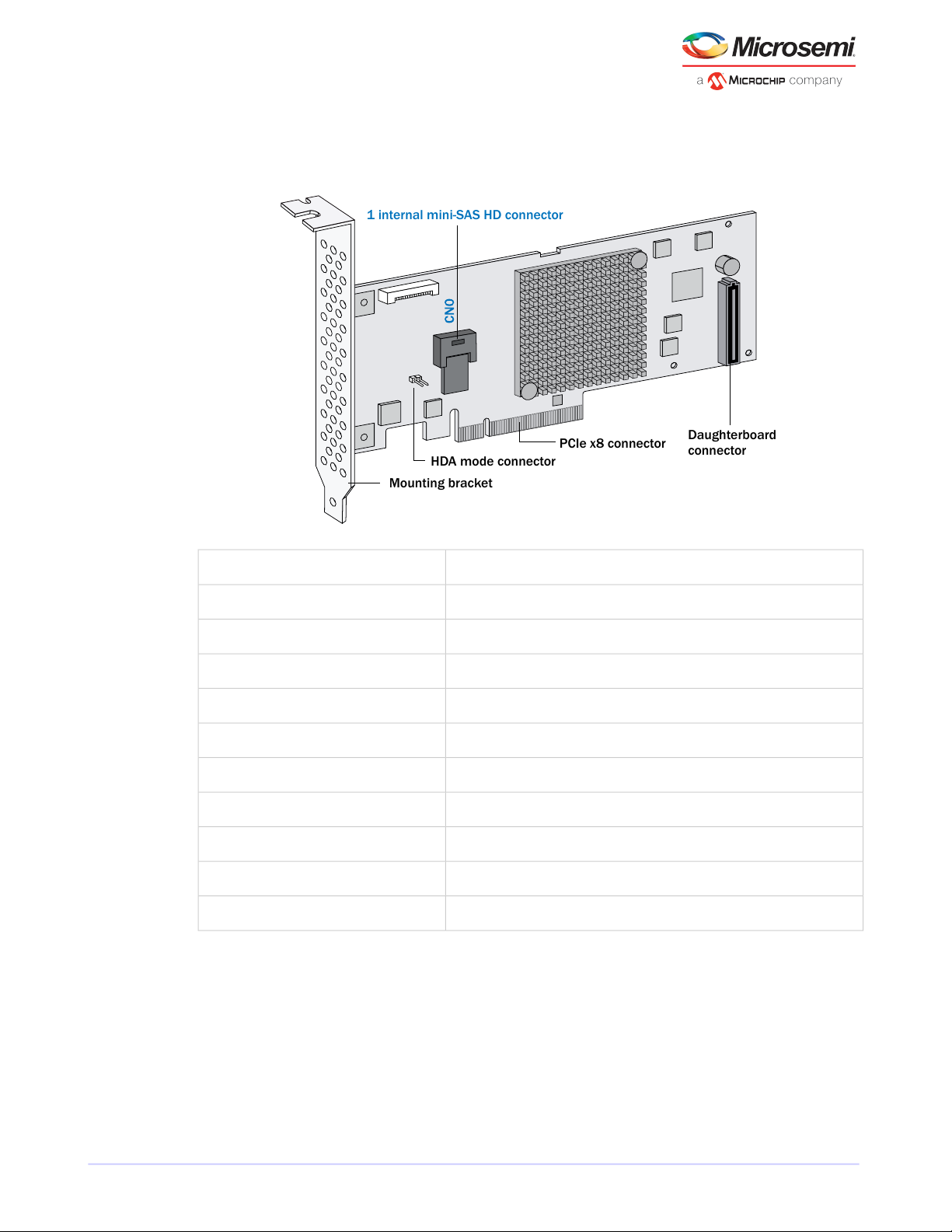
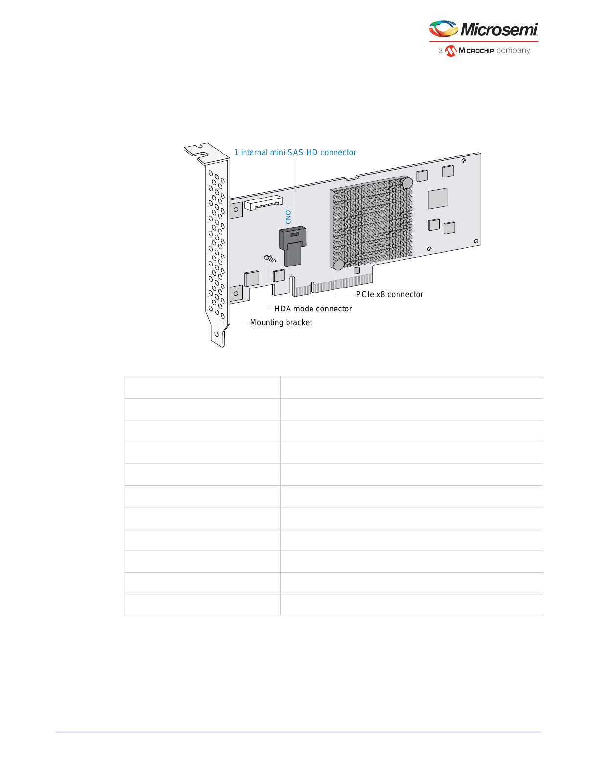
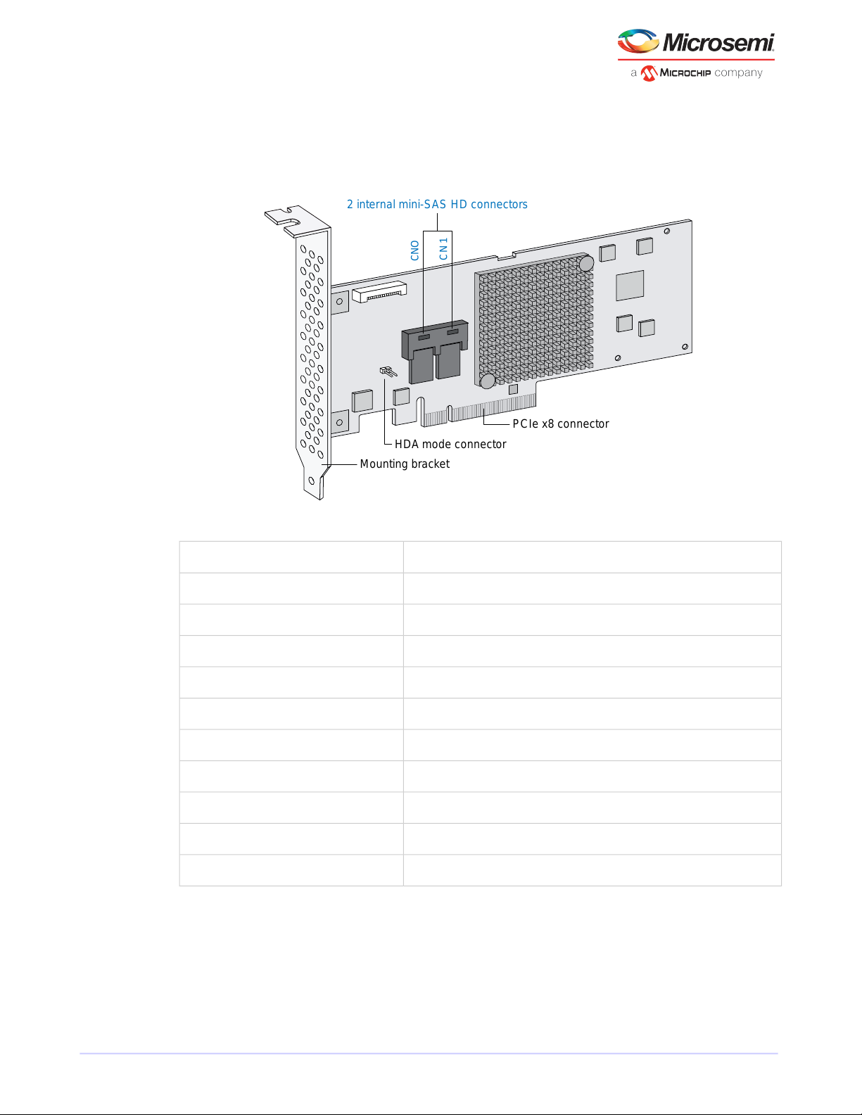
3.4 About the Microsemi Adaptec RAID 8405
The Microsemi Adaptec RAID 8405 is a SAS RAID controller with these features:
Low-prole MD2Form Factor
PCIe 3.0Bus compatibility
x8PCIe bus width
12 Gb/s per portData transfer rate
4Phys (Unied Serial Ports)
1024 MB DDR3Standard cache
1 mini-SAS HD x4 (SFF-8643)Connectors, internal
4 direct-attached (or up to 256 with expanders)Maximum number of disk drives
IBPI and SGPIO (Serial General Purpose Input/Output)Enclosure Support
YesOnboard speaker
Microsemi Adaptec Flash Backup Module AFM-700 (optional, sold separately)Zero Maintenance Cache Protection Module
Microsemi Proprietary and Condential. Installation and User's Guide Revision 5
6
Page 17
1 internal mini-SAS HD connector
HDA mode connector
Mounting bracket
PCIe x8 connector
CNO
About Your RAID Controller
3.5 About the Microsemi Adaptec RAID 8405E
The Microsemi Adaptec RAID 8405E is a SAS RAID controller with these features:
Low-prole MD2Form Factor
PCIe 3.0Bus compatibility
x8PCIe bus width
12 Gb/s per portData transfer rate
4Phys (Unied Serial Ports)
1024 MB DDR3Standard cache
1 mini-SAS HD x4 (SFF-8643)Connectors, internal
4 direct-attachedMaximum number of disk drives
IBPI and SGPIO (Serial General Purpose Input/Output)Enclosure Support
YesOnboard speaker
NoZero Maintenance Cache Protection Module
Microsemi Proprietary and Condential. Installation and User's Guide Revision 5
7
Page 18
PCIe x8 connector
Mounting bracket
2 internal mini-SAS HD connectors
Daughterboard
connector
HDA mode connector
About Your RAID Controller
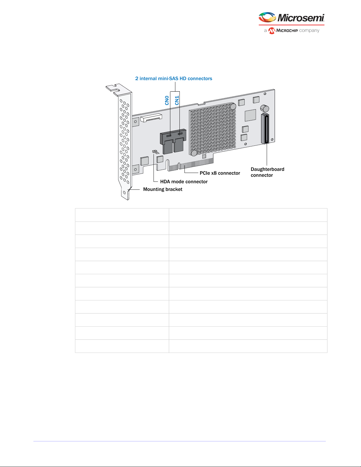
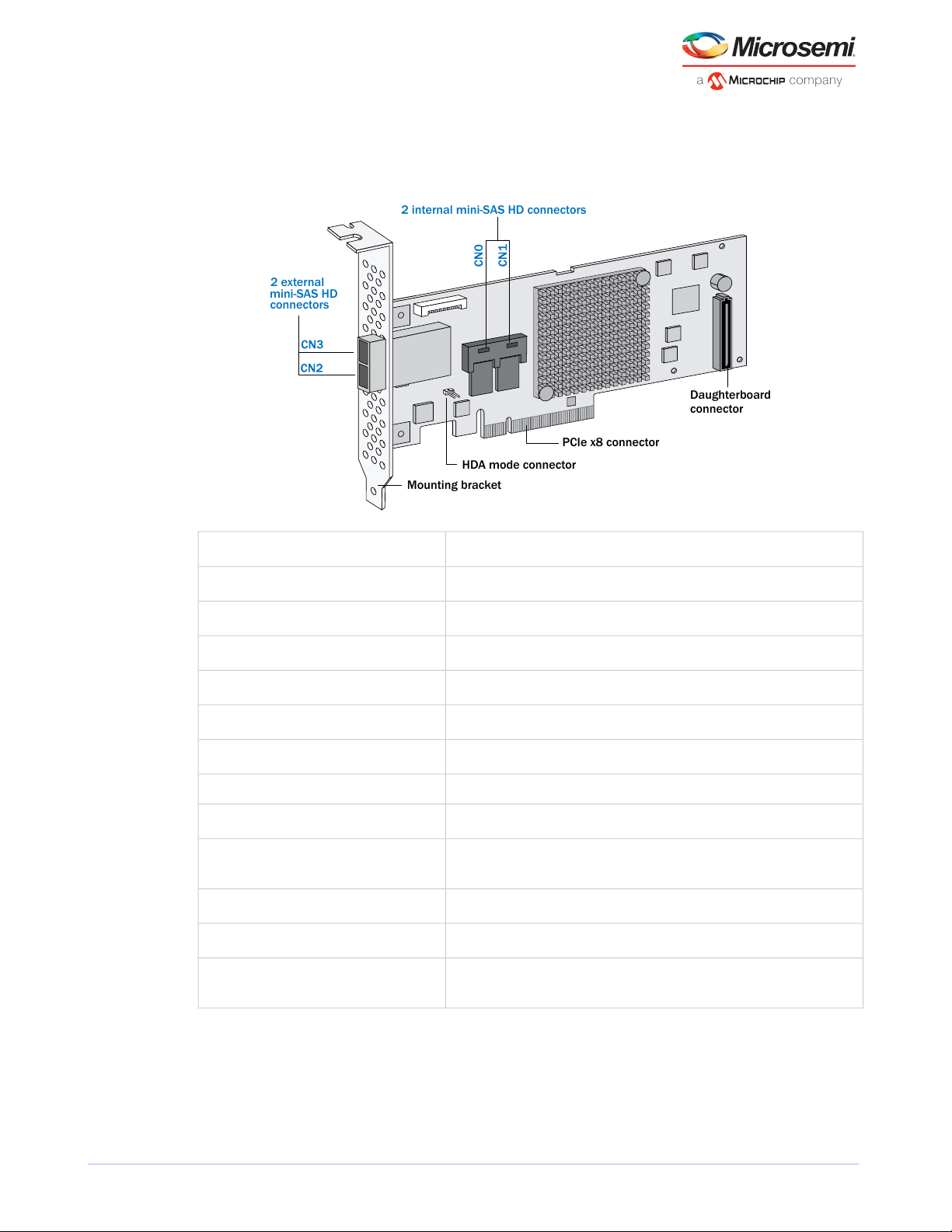
3.6 About the Microsemi Adaptec RAID 8805
The Microsemi Adaptec RAID 8805 is a SAS RAID controller with these features:
Low-prole MD2Form Factor
PCIe 3.0Bus compatibility
x8PCIe bus width
12 Gb/s per portData transfer rate
8Phys (Unied Serial Ports)
1024 MB DDR3Standard cache
2 mini-SAS HD x4 (SFF-8643)Connectors, internal
8 direct-attached (or up to 256 with expanders)Maximum number of disk drives
IBPI and SGPIO (Serial General Purpose Input/Output)Enclosure Support
YesOnboard speaker
Microsemi Adaptec Flash Backup Module AFM-700 (optional, sold separately)Zero Maintenance Cache Protection Module
Microsemi Proprietary and Condential. Installation and User's Guide Revision 5
8
Page 19
2 internal mini-SAS HD connectors
HDA mode connector
Mounting bracket
PCIe x8 connector
CNO
C N
1
About Your RAID Controller
3.7 About the Microsemi Adaptec RAID 8805E
The Microsemi Adaptec RAID 8805E is a SAS RAID controller with these features:
Low-prole MD2Form Factor
PCIe 3.0Bus compatibility
x8PCIe bus width
12 Gb/s per portData transfer rate
8Phys (Unied Serial Ports)
1024 MB DDR3Standard cache
2 mini-SAS HD x4 (SFF-8643)Connectors, internal
8 direct-attachedMaximum number of disk drives
IBPI and SGPIO (Serial General Purpose Input/Output)Enclosure Support
YesOnboard speaker
NoZero Maintenance Cache Protection Module
Microsemi Proprietary and Condential. Installation and User's Guide Revision 5
9
Page 20
PCIe x8 connector
Mounting bracket
2 external
mini-SAS HD
connectors
2 internal mini-SAS HD connectors
Daughterboard
connector
HDA mode connector
About Your RAID Controller
3.8 About the Microsemi Adaptec RAID 8885/8885Q
The Microsemi Adaptec RAID 8885/8885Q is a SAS RAID controller with these features:
maxCache SSD support
Zero Maintenance Cache Protection Module
Low-prole MD2Form Factor
PCIe 3.0Bus compatibility
x8PCIe bus width
12 Gb/s per portData transfer rate
16Phys (Unied Serial Ports)
1024 MB DDR3Standard cache
2 mini-SAS HD x4 (SFF-8643)Connectors, internal
2 mini-SAS HD x4 (SFF-8644)Connectors, external
16 direct-attached (or up to 256 with expanders)Maximum number of disk drives
8885Q: Up to 8 solid state drives, 2TB capacity, max. See the maxCache compatibility list at www.adaptec.com/compatibility.
IBPI and SGPIO (Serial General Purpose Input/Output)Enclosure Support
YesOnboard speaker
Microsemi Adaptec Flash Backup Module AFM-700 (8885: optional, sold separately; 8885Q: standard, pre-installed)
Microsemi Proprietary and Condential. Installation and User's Guide Revision 5
10
Page 21
PCIe x8 connector
Mounting bracket
2 internal mini-SAS HD connectors
2 internal
mini-SAS HD
connectors
Flash backup
connector
module
Stiffener (back of board)
HDA mode
connector
Reserved
About Your RAID Controller
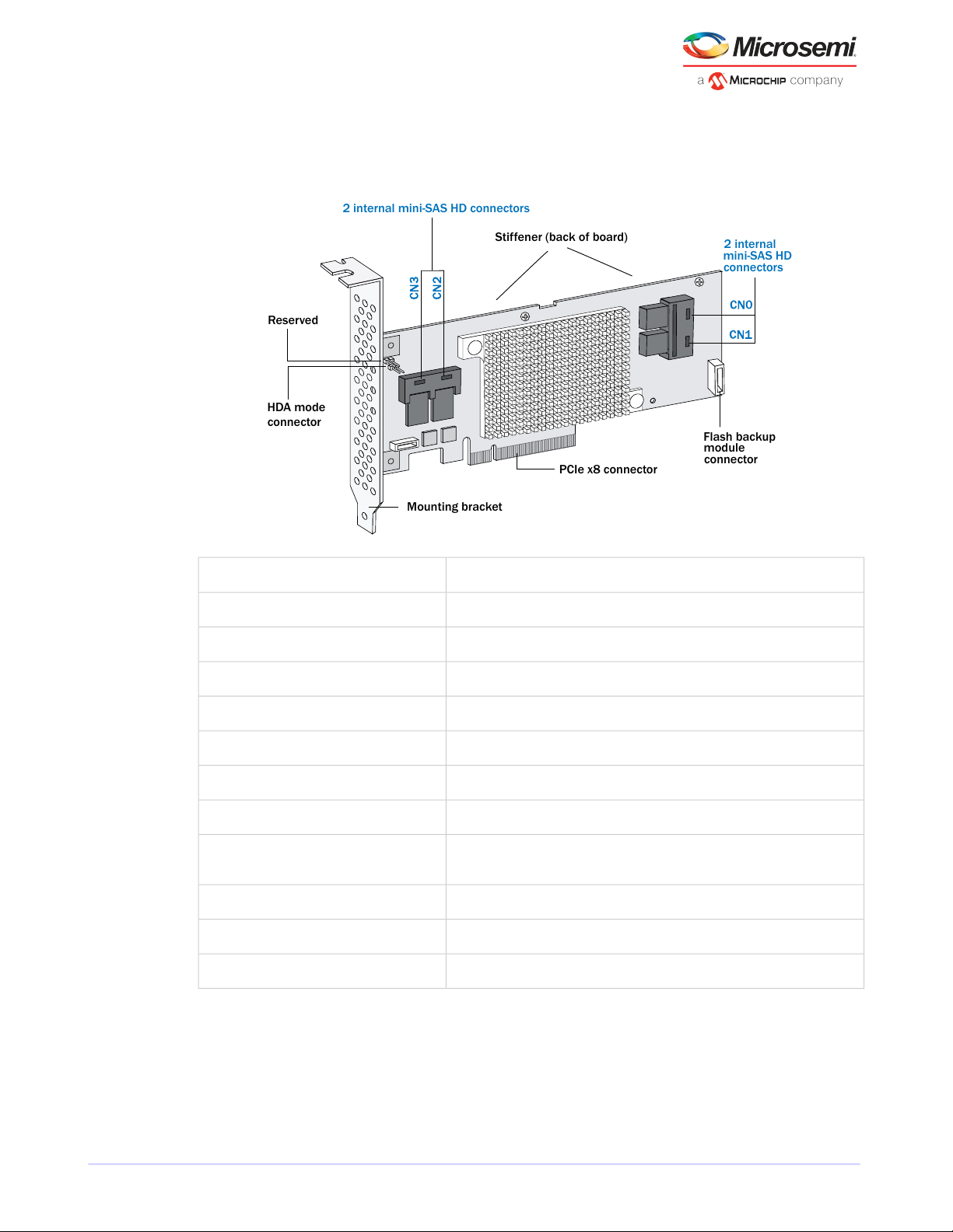
3.9 About the Microsemi Adaptec RAID 81605Z/81605ZQ
The Microsemi Adaptec RAID 81605Z/81605ZQ is a SAS RAID controller with these features:
maxCache SSD support
Low-prole MD2Form Factor
PCIe 3.0Bus compatibility
x8PCIe bus width
12 Gb/s per portData transfer rate
16Phys (Unied Serial Ports)
1024 MB DDR3Standard cache
4 mini-SAS HD x4 (SFF-8643)Connectors, internal
16 direct-attached (or up to 256 with expanders)Maximum number of disk drives
81605ZQ: Up to 8 solid state drives, 2TB capacity, max. See the maxCache compatibility list at www.adaptec.com/compatibility.
IBPI and SGPIO (Serial General Purpose Input/Output)Enclosure Support
YesOnboard speaker
Integrated Microsemi Adaptec Flash Backup Module AFM-700Zero Maintenance Cache Protection Module
Microsemi Proprietary and Condential. Installation and User's Guide Revision 5
11
Page 22

Getting Started
4 Getting Started
This chapter provides the basic information you need to set up your disk drives and arrays the way you
want them. It describes the options you have for installing your Microsemi Adaptec RAID controller and
disk drives and creating arrays for storage. It also describes how to prepare your controller for installation
into a low-prole computer cabinet.
4.1 Choosing a RAID Level
This section provides a brief overview of the RAID levels supported by your Microsemi Adaptec RAID
controller, including the minimum and maximum number of disk drives required by each.
Note: Before you begin, familiarize yourself with your controller's physical features and
the RAID levels that it supports (see Standard RAID Controller FeaturesRAID controllers
controllerscontrollers standard features on page 4).
• RAID 0 (Non-redundant Array)—Stripes data across multiple disk drives. Improved performance but
no redundancy (see Non-redundant Arrays (RAID 0)non-redundant arraysarrays non-redundantRAID
RAID 0RAID non-redundant arrays).
• RAID 1 Array—Created from two disk drives where one disk drive is a mirror of the other (the same
data is stored on each disk drive). Redundancy, but reduced capacity (see RAID 1 Arrays RAID RAID
1arrays RAID 1).
• RAID 1E Array—Similar to a RAID 1 array except that data is mirrored and striped, and more disk drives
can be included (see RAID 1 Enhanced ArraysRAID RAID 1Earrays RAID 1E).
• RAID 5 Array—Stripes data for improved performance and uses parity data to provide redundancy
(see RAID 5 ArraysRAID RAID 5arrays RAID 5).
• RAID 10 Array—Built from two or more equal-sized RAID 1 arrays, stripes and mirrors data across
multiple disk drives. Redundancy and improved performance (see RAID 10 ArraysRAID RAID 10arrays
RAID 10).
• RAID 50 Array—Built from multiple disk drives congured as two or more RAID 5 arrays, stripes stored
data and parity data across all disk drives (see RAID 50 ArraysRAID RAID 50arrays RAID 50).
• RAID 6 Array—Similar to a RAID 5 array except that it includes two independent sets of parity data
instead of one (see RAID 6 ArraysRAID RAID 6arrays RAID 6).
• RAID 60 Array—Similar to a RAID 50 array except that it includes four independent sets of parity data
instead of two (see RAID 60 ArraysRAID RAID 60arrays RAID 60).
See Comparing RAID Levels to see how manydisk drives you mustconnect to your RAID controller to support
the RAID level you want.
4.2 Selecting Disk Drives and Cables
4.2.1 Disk Drives
Your RAID controller supports SAS disk drives, SATA disk drives, and SATA and SAS Solid State Drives (SSDs).
When selecting disk drives for your RAID array, ensure that all the disk drives have the same performance
level. You can use different-sized disk drives in the array, but the array will be limited to the capacity of the
smallest and slowest disk drive. For more information about arrays, refer to the maxView Storage Manager
User’s Guide or online Help. For more information about compatible disk drives, refer to
www.adaptec.com/compatibility.
Microsemi Proprietary and Condential. Installation and User's Guide Revision 5
12
Page 23
Front of board
Full-height bracket
Back of board
Low-profle bracket
Getting Started
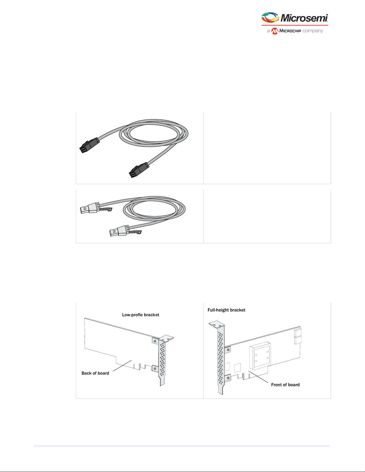
4.2.2 Cables
Depending on your requirements, you can use any of the cables listed below. Cable connectors are keyed
so thatyou can't insertthem incorrectly. For more information about cabling options for your RAIDcontroller,
visit www.adaptec.com.
Note: We recommend using only Microsemi Adaptec SAS cables.
SAS HD Cables (Series 8 controllers)
Internal SAS HD to SAS HD (SFF-8643 to SFF- 8643)—Connects to
a backplane or enclosure.
External SAS HD to SAS HD (SFF-8644to SFF-8644)—Connects to
a backplane or enclosure.
4.3 Replacing the Full-Height Bracket with a Low-Prole Bracket
If you are installing your Microsemi Adaptec RAID controller into a low-prole computer cabinet, replace
the original full-height bracket with the low-prole bracket included in your distribution kit. The full-height
bracket is mounted on the front of the controller, the low-prole bracket is mounted on the back of the
controller, as shown in the gure below.
To replace the full-height bracket with the low-prole bracket:
1. Remove the full-height bracket from the controller board. The full-height bracket is installed on the
front side of the controller, with the mounting screws inserted from the back of the controller, as shown
in the Figure 1.
Microsemi Proprietary and Condential. Installation and User's Guide Revision 5
13
Page 24
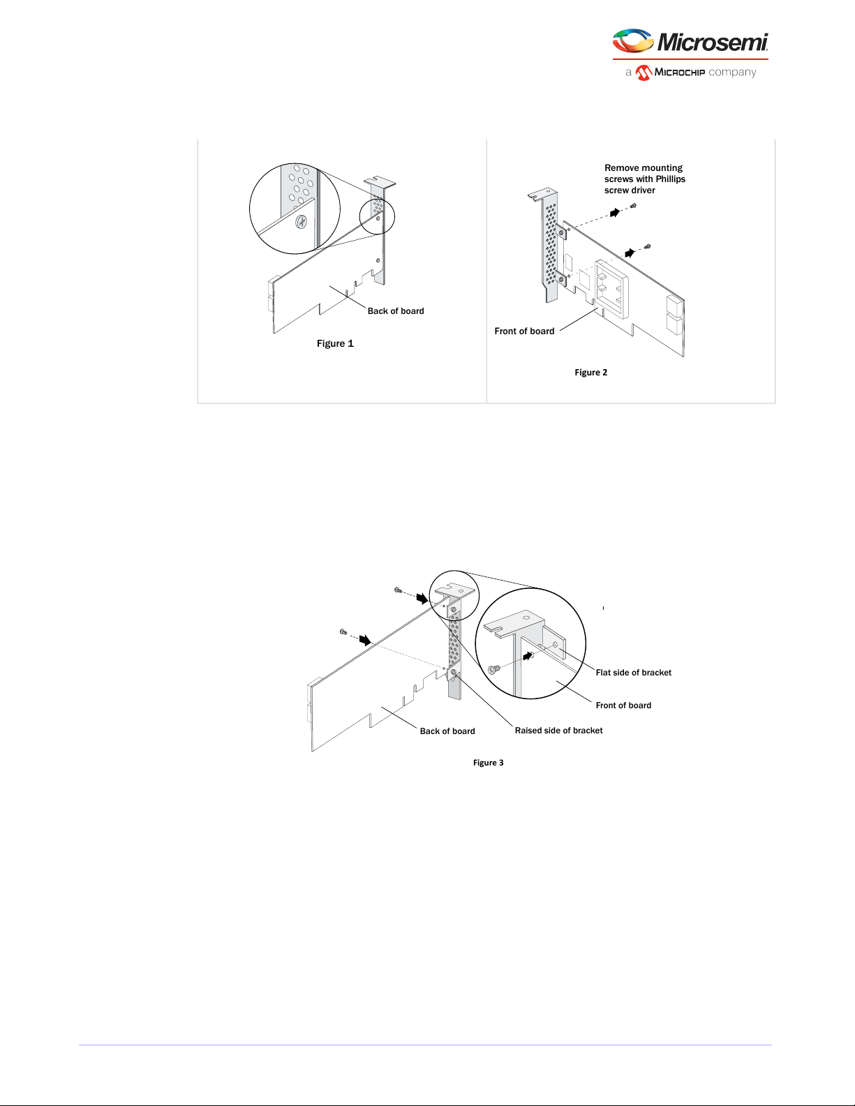
Remove mounting
screws with Phillips
screw driver
Front of board
Figure 2
Back of board
Figure 1
Figure 3
Raised side of bracket
Front of board
Flat side of bracket
Back of board
Getting Started
Using a Phillips head screw driver, remove the mounting screws, as shown in Figure 2, then set the
screws aside for use in the next step.
2. Attach the low-prole bracket to the controller board. The low-prole bracket is installed on the back
side of the controller, with the mounting screws inserted from the front of the controller, as shown the
Figure 3.
Insert the screws through the holes on the front of the controller, then fasten the screws to the bracket
with a Phillips screw driver.
Caution: The mount points on the low-prole bracket have a smooth or at side and
a raised side that looks like a spacer (see Figure 3). Be sure to install the bracket with
the at side against the controller PCB and the raised side facing away from the PCB.
Caution: The torque on the mounting screws should be a maximum of 3.0-4.0 lbf-in
to avoid deformation. Be sure that the controller is not bent after attaching the
low-prole bracket to the controller board.
4.4 Installation Options
When you install your Microsemi Adaptec RAID controller, you can choose to create a bootable array and
then install your operating system and the controller driver on that array.
Alternatively, you cancomplete a standard installation, where thecontroller driver isinstalled on an existing
operating system.
Microsemi Proprietary and Condential. Installation and User's Guide Revision 5
14
Page 25

Getting Started
4.5 Basic Installation Steps
This section describes the installation process. Follow the steps for the installation option you’ve chosen.
4.5.1 Installing with an Operating System
1. Install and connect your controller and internal disk drives (see Installing the Controller and Disk Drives).
If your controller has an external connector, you can connect external disk drives as well (or instead).
2. Set the boot controller (see Setting the Boot Controllerboot controllercontrollers setting boot controller).
3. Create a bootable array (see Creating an Array).
4. Install your operating system and the controller driver (see Installing the Driver and an Operating System
installation driver and operating systemdriver and operating system installationoperating system
installation.)
5. Install maxView Storage Manager and begin to manage your data storage (see Managing Your Storage
Spacetopic).
4.5.2 Installing on an Existing Operating System
1. Install and connect your controller and internal disk drives (see Installing the Controller and Disk Drives).
If your controller has an external connector, you can connect external disk drives as well (or instead).
2. Install the controller driver (see Installing the Driver on an Existing Operating System installation
driverdriver installation).
3. Install maxView Storage Manager and begin to manage your data storage (see Managing Your Storage
Spacetopic).
Microsemi Proprietary and Condential. Installation and User's Guide Revision 5
15
Page 26
Installing the Controller and Disk Drives
5 Installing the Controller and Disk Drives
This chapter explains howto install your Microsemi Adaptec RAID controller, and how to install andconnect
internal and external disk drives.
5.1 Before You Begin
• Read Safety Informationsafety information.
• Familiarize yourself with your RAID controller's physical features and the RAID levels that it supports
(see Standard RAID Controller FeaturesRAID controllers controllerscontrollers standard features).
• Ensure you have the right number of disk drives for the RAID level you want to use for your arrays (see
Selecting Disk Drives and Cables controllers disk drivesdisk drives).
• If you are installing the RAID controller into a low-prole computer cabinet, replace the original
full-height bracket with the low-prole bracket included in the kit (see Replacing the Full-Height Bracket
with a Low-Prole Bracket).
5.2 Installing the Controller
This section describes how to install the RAID controller into your computer cabinet. Microsemi Adaptec
RAID controllers come in two basic congurations: standard and zero maintenance cache protection with
batteryless backup (ZMCP). ZMCP uses ash memory and a supercapacitor module to protect the cache
without a battery.
Follow one of these sets of instructions:
• To install a Microsemi Adaptec RAID controller without zero maintenance cache protection, see the
next section.
• To install a Microsemi Adaptec RAID controller with zero maintenance cache protection, see Installing
a RAID Controller with Zero Maintenance Cache Protection batteryless backup zero maintenance cache
protection .
Caution: Be sure to handle the controller by its bracket or edges only.
5.2.1 Installing a RAID Controller without Zero Maintenance Cache Protection
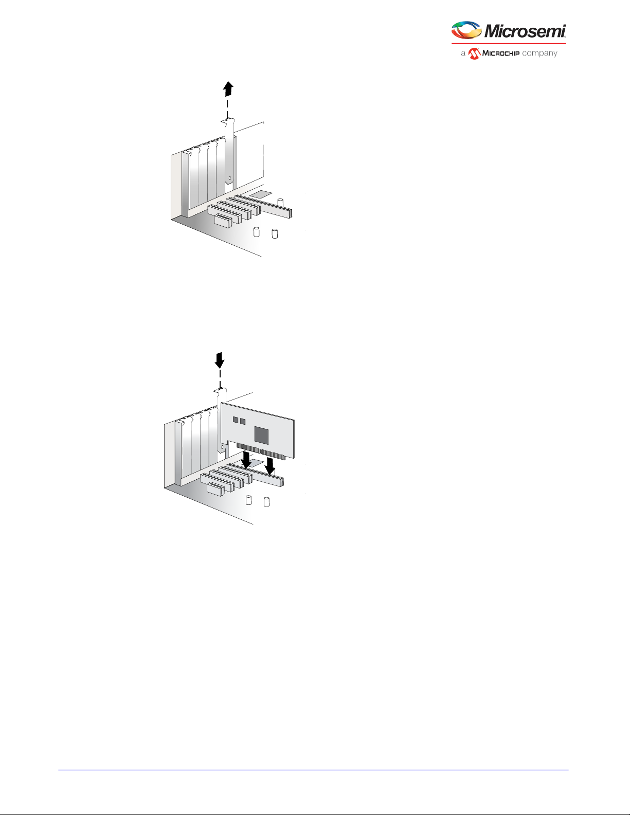
To install a Microsemi Adaptec RAID controller without zero maintenance cache protection:
1. Turn off your computer and disconnect the power cord. Open the cabinet, following the manufacturer's
instructions.
2. Select an available PCIe expansion slot that's compatible with your RAID controller and remove the slot
cover, as shown below. (PCIe bus compatibility is marked to the controller gures in About Your RAID
Controllercontrollers gurescontrollers descriptions.)
Microsemi Proprietary and Condential. Installation and User's Guide Revision 5
16
Page 27
Installing the Controller and Disk Drives
3. Insert the RAID controller into the expansion slot and press down gently but rmly until it clicks into
place. When installed properly, the RAID controller should appear level with the expansion slot.
Caution: Touch a grounded metal object before handling the RAID controller.
4. Secure the bracket in the expansion slot, using the retention device (for instance, a screw or lever)
supplied with your computer.
5. Prepare and install your internal disk drives, following the instructions in Connecting Disk Drives to Your
Controllersinstallation disk drivesdisk drives connecting to controllerscontrollers connecting disk drives.
If you are not installing internal disk drives, close your computer cabinet, reattach the power cord, then
continue with Connecting External Devices installation external devicesexternal devicescontrollers
connecting external devicesdisk drives external.
5.2.2 Installing a RAID Controller with Zero Maintenance Cache Protection
Microsemi Adaptec RAID controllers with zero maintenance cache protection include a ash module
daughterboard and a supercapacitor module. On Microsemi AdaptecSeries Qcontrollers, thedaughterboard
is pre-installed. On Microsemi Adaptec RAID controllers with optional zero maintenance cache protection
(see Adding a Flash Backup Module), the daughterboard is user installed. The supercapacitor module is
always user installed.
Microsemi Proprietary and Condential. Installation and User's Guide Revision 5
17
Page 28

Mounting clip
Recessed side
Large friction
clip
Installing the Controller and Disk Drives
The following instructions describe how to install the RAID controller and supercapacitor module on a
Microsemi Adaptec Series 8/8ZQ controller using the mounting plate method. It assumes that the
daughterboard is already installed.
Warning: Do NOT remove or insert a fully charged supercapacitor module. Always
discharge the unit rst to avoid damage to the controller or ash backup module. The
factory ships with discharged units, so they are safe to install when you receive them. To
ensure that an installed unit is discharged, switch your system OFF, then wait 5 minutes.
After a dirty shutdown, wait 3 minutes after backup is complete, then remove the unit.
To install a Microsemi Adaptec RAID controller with zero maintenance cache protection:
1. Assemble the mounting plate and attach the supercapacitor module:
a. Attach the full-height bracket and mounting clip to the mounting plate. The full-height bracket is
installed on the front side of the mounting plate (the side with the bents), with the mounting screws
inserted from the back, as shown in the gure below. (Be sure to attach the mounting plate to the
bracket with recessed side at the bottom!) Attach the mounting clip to the front of the mounting
plate with four (4) Phillips screws. The large friction clip should face the front of the mounting plate.
b. Insert the supercapacitor module into the mounting clip. The supercapacitor module snaps securely
into place between the large and small friction clips, as shown in the gure below. Be sure to orient
the supercapacitor module such that the connecting cable faces the rear of the mounting plate.
c. Set the mounting plate aside; continue with the steps below.
2. Turn off your computer and disconnect the power cord. Open the cabinet, following the manufacturer's
instructions.
3. Select an available PCIe expansion slot that's compatible with your RAID controller and remove the slot
cover, as shown in the gure below. (PCIe bus compatibility is marked on the controller gures in About
Your RAID Controllercontrollers gurescontrollers descriptions.) Be sure to choose a slot in the backplane
with an empty slot next to it; you will use the empty slot to install the supercapacitor mounting plate,
after you install the controller. Remove the slot cover for the mounting plate, then continue with the
next step.
Microsemi Proprietary and Condential. Installation and User's Guide Revision 5
18
Page 29

Extender cable
Installing the Controller and Disk Drives
4. Insert the RAID controller into the expansion slot and press down gently but rmly until it clicks into
place. When installed properly, the RAID controller should appear level with the expansion slot. Secure
the bracket in the expansion slot, using the retention device (for instance, a screw or lever) supplied
with your computer.
Caution: Touch a grounded metal object before handling the RAID controller.
5. Attach the supercapacitor module to the RAID controller by inserting the connector into the socket on
the ash module daughterboard, as shown in the gure below. (The connector attaches to the socket
in only one direction.) Use the included extender cable if you need extra length to reach the connector
on the daughterboard.
6. Install the mounting plate in the empty slot next to the controller, as shown in the next gure. After
securing the mounting plate to the card cage, verify that the supercapacitor module and mounting plate
sit above (and do not touch) the PCIe slot.
Microsemi Proprietary and Condential. Installation and User's Guide Revision 5
19
Page 30

GapGap
Installing the Controller and Disk Drives
7. Prepare and install your internal disk drives, following the instructions in Connecting Disk Drives to Your
Controllersinstallation disk drivesdisk drives connecting to controllerscontrollers connecting disk drives.
If you are not installing internal disk drives, close your computer cabinet, reattach the power cord, then
continue with Connecting External Devices installation external devicesexternal devicescontrollers
connecting external devicesdisk drives external.
8. Restart your computer.
The supercapacitor starts charging automatically. It should reach full charge in 5-6 minutes.
5.3 Connecting Disk Drives to Your Controllers
You can connect SAS disk drives, SATA disk drives, and SATA and SAS Solid State Drives (SSDs) to your
Microsemi Adaptec RAID controller. (See www.adaptec.com/compatibility for a list of compatible drives.)
There are no jumpers or switches to set before installation.
If you plan to build a bootable array, ensure that you install at least the minimum number disk drives
required to support the RAID level you want. See Choosing a RAID LevelRAID levelscontrollers RAID levels
for more information.
Note: Although you can connect both SAS and SATA disk drives to your SAS controller,
we recommend that you do not combine SAS and SATA disk drives within the same array.
See What is SAS?SAS description for more information.
You have two connection options:
• To connect directly to the controller, see the following section.
• To connect to a backplane, see Connecting Drives to a System Backplaneinstallation backplanebackplane
connections.
To connect Solid State Drives to your controller, see Connecting Solid State Drives (SSDs) maxCache Solid
State Drive installinginstallation solid state drivesSolid State Drive (SSD) installing.
5.3.1 Connecting Drives Directly to the Controller
In a direct-attach connection, SAS or SATA disk drives are connected directly to a SAS card with SAS cables.
The number of direct-attached disk drives is limited to fourper internal SAS connector. (For moreinformation
about direct-attach connections, see How are Disk Drives Identied in SAS? SAS disk drive identiersdisk
drives SAS identiersdisk drivesSAS disk drives.)
1. Install your internal SAS or SATA disk drives, following the instructions in your system's documentation.
2. Use internal SAS, mini-SAS, or mini-SAS HD cables to attach the disk drives to the controller, as required.
Microsemi Proprietary and Condential. Installation and User's Guide Revision 5
20
Page 31

Installing the Controller and Disk Drives
3. When all internal disk drives have been installed and attached to the controller, close your computer
cabinet, reattach the power cord, then continue with Connecting External Devices installation external
devicesexternal devicescontrollers connecting external devicesdisk drives external.
5.3.2 Connecting Drives to a System Backplane
In a backplane connection, disk drives and SAS cards are attached to and communicate with each other
through a system backplane.
The number of disk drives is limited to the number of slots available on the backplane. Some backplanes
have embedded SAS expanders and can support up to 128 end devices. (For more information about
backplane and expander connections, seeHow are Disk Drives Identied in SAS? SAS disk drive identiersdisk
drives SAS identiersdisk drivesSAS disk drives.)
1. Connect one or more internal SAS or SATA disk drives to the backplane. (Refer to your system's
documentation for more information.)
2. Use an internal mini-SAS or mini-SAS HD cable to connect the controller to the backplane, as required.
3. When all internal disk drives have been installed and connected, close your computer cabinet, reattach
the power cord, then continue with Connecting External Devices installation external devicesexternal
devicescontrollers connecting external devicesdisk drives external.
5.3.3 Connecting Solid State Drives (SSDs)
To connect a Solid State Drive to your controller, you can use a direct-attached connection or a backplane
connection, as required. If your server does not have a standard 2.5-inch drive tray, you must use a
bracket/SLED which enables the SSD to t properly.
Note: For Microsemi Adaptec maxCache applications or hybrid RAID arrays (comprised
of hard drives and SSDs) you can use any Solid State Drive on the compatibility list. See
www.adaptec.com/compatibility for a list of compatible SSDs. maxCache is supported on
Microsemi Adaptec Series Q controllers only.
In a direct-attach connection (described in the steps below), you connect SSDs directly to the controller
with SAScables (mini-SAS to SATA). Ina backplaneconnection, use the appropriate cable for your backplane
type (see Connecting Drives to a System Backplaneinstallation backplanebackplane connections for more
about backplane connections). For maxCache caching applications, you can connect a maximum of 8
maxCache-compatible SSDs to a controller. For RAID arrays, Microsemi Adaptec controllers support a
maximum of 256 drives, including SSDs (for details, see About Your RAID Controllercontrollers
gurescontrollers descriptions).
1. Install the SSDs in your server. For servers with a standard 2.5-inch drive tray, install the SSD directly
into the tray. If your server does not have a standard 2.5-inch drive tray, use a bracket or adapter which
enables it to t properly.
Microsemi Proprietary and Condential. Installation and User's Guide Revision 5
21
Page 32

Typical SSD installation
Use a 2.5” to 3.5” adapter to
install your SSD if server does
not have 2.5” tray.
To other SSDs
SSD connected to controller with
internal mini-SAS HD to SATA Fanout cable
Single-port connectorInternal x4 mini-SAS HD connector
Installing the Controller and Disk Drives
5.4 Connecting External Devices
2. Use aninternal mini-SAS or mini-SAS HD to SATA cable, as required, to attachthe SSD(s)to the controller,
as shown in the example below.
3. When all SSDs have been installed and connected, close your computer cabinet, reattach the power
cord, then continue with Connecting External Devices installation external devicesexternal
devicescontrollers connecting external devicesdisk drives external.
Note: If you are not connecting any external devices, see the following section, Next
Steps.
Use high-quality cables to connect your controller to your external device(s), such as disk drives or disk
drive enclosures.
Microsemi Proprietary and Condential. Installation and User's Guide Revision 5
22
Page 33

Installing the Controller and Disk Drives
We recommend using only Microsemi Adaptec cables. For more information about cabling options for your
controller, see Cablescontrollers SAS cablesSAS cables on page 13.
5.5 Next Steps
If you are installing the controller driver and an operating system onto a bootable array, continue with
Creating a Bootable Array.
If you are completing a standard installation onto an existing operating system, continue with Installing the
Driver on an Existing Operating System installation driverdriver installation.
Microsemi Proprietary and Condential. Installation and User's Guide Revision 5
23
Page 34

Creating a Bootable Array
6 Creating a Bootable Array
This chapter explains how to set your Microsemi Adaptec controller to be the boot controller, and how to
create a bootable array.
Note: If you are completing a standard installation onto an existing operating system,
you don't have to complete this task. Skip to Installing the Driver on an Existing Operating
System installation driverdriver installation.
6.1 Setting the Boot Controller
Note: If your system won't contain more than one bootable controller, skip to the next
section, Creating an Array.
Your Microsemi Adaptec RAID controller supports bootable disk drives and bootable arrays. To enable your
system to boot from either a disk drive or an array connected to your controller:
1. Enter the system setup.
2. Navigate to the drive boot sequence.
3. Move the boot controller to the top of the list.
For more information, refer to your computer documentation.
6.2 Creating an Array
This section explains how to create an array.
A RAID 5 array is created in the examples shown in this section because RAID 5 provides the most security
and best performance with a minimum of three disk drives. However, you can choose to create an array
with a different RAID level; you can also change array level later, after the operating system is installed.
You can create an array using any of these tools:
• Microsemi Adaptec RAID Conguration Utility (ARC)—BIOS-based menus and keyboard navigation
(see the following section).
• maxView Storage Manager—Graphical software application (running from a bootable USB image) that
you can navigate with your mouse (see About maxView Storage Managerconcept).
• ARCCONF—Command line utility. For instructions, refer to the Microsemi Adaptec RAID Controller
Command Line Utility User's Guide.
You can use any of these tools, but the ARC utility is the quickest and easiest tool for this task.
Note: We recommend that you do not combine SAS and SATA disk drives within the same
array. maxView Storage Manager displays a warning if you try to create a logical drive
using a combination of SAS and SATA disk drives. See What is SAS?SAS description for
more information.
6.2.1 Creating an Array with the ARC Utility
The ARC utility is menu-based. Instructions for completing tasks appear on-screen. Menus can be navigated
using the arrows, Enter, Esc, and other keys on your keyboard.
To create a RAID 5 array:
1. Power on your computer. When prompted, press Ctrl+A to enter the ARC utility.
Note: On computers that support the Unied Extensible Firmware Interface, or uEFI,
ARC utility options are presented with a uEFI/HII interface rather than the Microsemi
Microsemi Proprietary and Condential. Installation and User's Guide Revision 5
24
Page 35

Creating a Bootable Array
Adaptec Ctrl-A interface described below. To begin using the ARC utility with the
uEFI/HII interface, see Ctrl-A or uEFI/HII? Unied Extensible Firmware Interface
(uEFI)Human Interaction Infrastructure Interface (HII)HII interfaceuEFI on page 57.
2. If youhave more than one controller of the same model or family inyour computer, select your controller,
then press Enter .
3. Select Logical Device Conguration, then press Enter .
4. Select Initialize Drives, then press Enter .
5. Select at least three disk drives for the array, press Insert for each selected disk drive, then press
Enter.
Caution: During initialization, all data is deleted from the disk. Before continuing,
back up any data you want to keep.
6. Press Y , then press Enter .
The selected disk drives are initialized, then the Logical Device Conguration screen appears.
7. Select Create Array, then press Enter .
8. Select the disk drives that were just initialized, press Insert for each selected disk drive, then press
Enter .
9. When the Array Properties screen opens, follow the instructions in the following table.
Entry or SelectionProperty Line
Array Type
Array Label
Array Size
Stripe Size
Read Caching
Write Caching
Create RAID via
MaxCache Read
MaxCache Write
[Done]
Select RAID 5, then press Enter .
Type a name, then press Enter.
Press Enter , then press Enter again to use the default granularity of GB.
Press Enter to use the default (256 KB).
Note: This property applies only to striped arrays (RAID 0, 1E, 10, 5, 50, 5EE, 6,
and 60).
Press Enter to use the default (Enable).
Press Enter to use the default (Enable always), then press Yto conrm.
Press Enter to use the default (Build/Verify).
Press Enter to use the default (Enable)
Press Enter to use the default (Disable)
Press Enter .
10. When a cache warning message displays, type Y .
11. Once the array is created, a message displays telling you that the array can now be used. Press any key
to return to the Logical Device Conguration menu.
You can start using the array immediately. However, performance is reduced until the build process is
complete.
12. Press Esc until the Exit utility window appears.
13. Select Yes, then press Enter.
The computer restarts.
Microsemi Proprietary and Condential. Installation and User's Guide Revision 5
25
Page 36

Creating a Bootable Array
14. Continue with Making Your Array Bootablearrays making an array bootablebootable arrays.
6.2.2 Creating an Array with maxView Storage Manager
This section describes how to use the maxView Storage Manager conguration wizard to build an array.
Note: Before you begin, download the maxView Storage Manager bootable USB image
at start.microsemi.com, then copy the bootable image to a USB ash drive. For details,
refer to the maxView Storage Manager User's Guide.
To create a RAID 5 array:
1. Insert the bootable USB drive on the machine you want to congure.
The Boot menu opens in a shell window.
2. Select Launch maxView from the menu.
After a minute or so, the maxView Storage Manager login screen opens in a browser window.
3. Enter root/root for the login credentials.
4. On the ribbon, in the Logical Disk group, click Create Logical Drive.
5. When the wizard opens, ensure that Express Conguration is selected, then click Next.
6. Review the logical drive conguration summary.
Note: maxView Storage Manager uses the term logical drive when referring to an
array (see Terminology Used in this Guideterminology).
The following example shows a RAID 5 array, ready to be created.
Microsemi Proprietary and Condential. Installation and User's Guide Revision 5
26
Page 37

Creating a Bootable Array
7. Click Finish.
maxView Storage Manager builds the logical drives.
8. Partition and format the logical drive(s).
The logical drives you created appear as a physical disk drives on your operating system. You must
partition and format these logical drives before you can use them to store data.
9. Close all windows, remove the bootable USB drive, then restart your system.
For information about installing and using maxView Storage Manager as a full software application, see
the maxView Storage Manager User's Guide.
10. Continue with the following section.
6.3 Making Your Array Bootable
Use the ARC Utility to make the array bootable (see Creating Bootable ArraysARC creating bootable
arraysarrays creating bootable arraysbootable arrays creating).
Then continue with Installing the Driver and an Operating System installation driver and operating
systemdriver and operating system installationoperating system installation.
Microsemi Proprietary and Condential. Installation and User's Guide Revision 5
27
Page 38

Installing the Driver and an Operating System
7 Installing the Driver and an Operating System
This chapter explains how to install your Microsemi Adaptec RAID controller driver and an operating system
on a bootable array (see Creating a Bootable Array bootable arrays creatingarrays (bootable)).
Note:
1. To install the driver on an existing operating system, see Installing the Driver on an
Existing Operating System installation driverdriver installation.
2. To install the Linux drivers from source with Dynamic Kernel Module Support (for
persistence across across kernel updates), download the Linux Driver Source Code
package from the support page for your product at start.microsemi.com, then follow
the instructions in the embedded Readme.
7.1 Before You Begin
• Install and connect your RAID controller and internal disk drives (see Installing the Controller and Disk
Drives).
• Create a bootable array (see Creating a Bootable Array bootable arrays creatingarrays (bootable)).
• Download drivers from the web
• Create a driver disk (see the following section)
7.2 Creating a Driver Disk
Download the latest drivers from the Web, then create a driver disk by completing the steps below. You
will need a USB ash drive to complete this task. If the driver binary is an iso image, use a writable CD
instead of a ash drive.
To download drivers and create a driver disk:
1. Open a browser window, then type start.microsemi.com in the address bar.
2. Select your RAID controller family and controller model.
3. Select your operating system version, then select the appropriate driver from the list.
Note: For Linux OSs, the list of drivers typically includes a rpm le and an Images le.
Select the Images le only if you are installing the driver on an existing operating
system (for more information, see Installing the Driver on an Existing Operating System
installation driverdriver installation).
4. Click Download Now and accept the license agreement.
5. When the download completes, extract the contents of the driver archive le to a temporary location.
If the archive includes drivers for multiple operating system versions (Windows, for instance), each
driver is stored in a separate folder.
6. Change to the folder for your operating system version, as needed.
7. Copy the driver binary le or the entire driver folder contents to a USB ash drive. For Debian, Ubuntu,
and Fedora Linux, be sure to extract the contents of the .tgz les rst.
If the driver binary is an iso image, see Step [ 8 ] .
8. If the driver binary is an iso image for instance, for Citrix XenServer burn the iso to a writeable CD.
Use whatever tool you prefer to burn the CD, such as an interactive, GUI-based, tool or the Linux
command line.
Note: For VMware ESXi 5.5 and VMware ESXi 6.0, see Installing with VMware ESXi .
Microsemi Proprietary and Condential. Installation and User's Guide Revision 5
28
Page 39

Installing the Driver and an Operating System
9. Remove and label the driver disk.
10. Continue the installation with the instructions for your operating system.
7.3 Installing with Windows
Note: The following instructions apply to all supported Windows operating systems. You
need the Windows installation DVD (or equivalent virtual media/iso image) to complete
this task.
To install the Microsemi Adaptec RAID controller driver while installing Windows:
1. Insert your Windows DVD, then restart the computer.
2. Follow the on-screen instructions to begin the Windows installation.
3. When prompted to specify a location for Windows, select Load Driver.
4. Insert the USB driver disk, browse to the driver location, then click OK.
5. When the driver is found, press Next.
Note: You may see the message ‘No drives were found’. Repeat [ 3 ] , [ 4 ] (browse
to driver location), and [ 5 ] . On the second attempt, the driver will load successfully.
6. Click Next again to accept the default partition conguration, or refer to your Windows documentation
to congure partitions manually.
7. Follow the on-screen instructions to complete the installation.
8. Continue with Managing Your Storage Spacetopic.
7.4 Installing with Red Hat Linux or CentOS
Note: You will need the Installation DVD (or equivalent virtual media/iso image) for your
operating system to complete this task. You must have root privilege to install the driver
image.
To install the Microsemi Adaptec RAID controller driver while installing Red Hat Linux or CentOS:
1. Insert your installation DVD.
2. Restart your computer.
3. When the rst installation screen appears, insert the USB driver disk.
4. Type this command at the Boot: prompt, then press Enter:
linux dd
5. Select Yes to indicate that you have a driver disk, browse the USB drive (typically, /dev/sda1), then
select the driver image.
6. Verify that the driver is loaded, then complete the installation following the on-screen instructions.
7. Continue with Managing Your Storage Spacetopic.
7.5 Installing with SuSE Linux Enterprise Server
Note: You need the SuSE installation DVD (or equivalent virtual media/iso image) to
complete this task.
To install the Microsemi Adaptec RAID controller driver while installing SuSE Linux:
1. Insert the SuSE Installation DVD.
Microsemi Proprietary and Condential. Installation and User's Guide Revision 5
29
Page 40

Installing the Driver and an Operating System
2. Restart your system.
3. When the installation selectionscreen appears, choose the type of installation you want, press F5(SuSE
10) or F6 (SuSE 11), then select Yes to indicate that you have a driver disk.
4. Insert the USB driver disk.
5. (SuSE 11 SP3 only) Add 'brokenmodules=aacraid dud=1' to the Boot menu. This step ensures that the
installer loads from the driver disk, not the in-box driver.
6. When prompted to "Please choose the Driver Update medium", highlight the USB partition, then select
OK.
Note: If the "choose Driver Update medium" screen is displayed again, assume that
the driver was accepted; select Back, then press Enter.
7. (SuSE 11 SP3 only) On the "Welcome screen", switch to the console by typing CTRL+ALT+F2, then type
this command:
insmod ./update/000/modules/aacraid.ko
Press CTRL+ALT+F7 to return to the Welcome screen.
8. Complete the installation, following the on-screen instructions.
9. Continue with Managing Your Storage Spacetopic.
7.6 Installing with Ubuntu Linux
Note: You need the Ubuntu installation DVD (or equivalent virtual media/iso image) to
complete this task. You must have root privilege to install the driver image.
To install the Microsemi Adaptec RAID controller driver while installing Ubuntu Linux:
1. Insert the Ubuntu Installation DVD, then restart your computer.
2. When the installation menu appears, select Install Ubuntu Server. Continue the installation until the
"Congure Network" screen appears, then type CTRL+ALT+F2 to switch to the console.
3. Insert the USB driver disk, then type the following command to scan for the device:
fdisk -l
4. Assuming the USB drive is assigned to /dev/sda1, type the following commands to begin loading the
driver:
mkdir mnt2 /AACRAID
mount /dev/sda1 /mnt2
cp -R /mnt2/* /AACRAID
umount /mnt2
Note: The following steps assume you are installing Ubuntu 12 or higher.
5. Copy the driver le to the /lib/modules directory:
rmmod aacraid
cp -f /AACRAID/aacraid.ko
/lib/modules/3.16.0-23-generic/kernel/drivers/scsi/aacraid/aacraid.ko
6. Remove the USB drive.
Microsemi Proprietary and Condential. Installation and User's Guide Revision 5
30
Page 41

Installing the Driver and an Operating System
7. Install the loadable module:
insmod /lib/modules/3.16.0-23-generic/kernel/drivers/scsi/aacraid/aacraid.ko
8. Press CTRL+ALT+F1 to switch back to the installation screen, then follow the on-screen prompts to
continue the installation.
Note: Do not press Continue at the end of the installation until you complete Step [
9 ] !
9. When prompted to reboot the system, press CTRL+ALT+F2 to switch to the console.
10. Type the following commands to complete the driver installation:
cp -f /AACRAID/aacraid.ko
/target/lib/modules/3.16.0-23-generic/kernel/drivers/scsi/aacraid/aacraid.ko
chroot /target
/sbin/depmod -a 2.6.32-28-server
update-initramfs -u -v
exit
11. Press CTRL+ALT+F1 to switch back to the installation screen, then reboot.
12. Continue with Managing Your Storage Spacetopic.
7.7 Installing with VMware
Note: You will need a writable CD or USB ash drive to complete this task. You must have
administrator privileges to create the driver disk and install the driver image.
To install the RAID controller driver with VMware ESXi 6.0 or VMware ESXi 6.5, you must create a custom
boot imageusing theESXi-Customizer tool.This tool automates theprocess of customizing the ESXiinstall-ISO
and runs as a script under Microsoft PowerShell.
You can download the ESXi-Customizer tool, ESXi-Customizer-PS-v2.5.ps1, from
https://www.v-front.de/p/esxi-customizer-ps.html and other locations on the Web.
Note: Be sure to install the prerequisite software rst, including Powershell and VMware
POWERCLI, before you install ESXi-Customizer.
Note: VMware 6.0 driver supports VMware 6.5.
To install the RAID controller driver while installing VMware:
1. Download and install Microsoft PowerShell and VMware POWERCLI, as needed. You can download
PowerShell from the Microsoft Download Center at www.microsoft.com/download, and POWERCLI
from my.vmware.com.
Note: PowerShell is pre-installed on many Windows systems, including Windows
Server 2012 and Windows Server 2016.
2. Download the ESXi-Customizer tool from https://www.v-front.de/p/esxi-customizer-ps.html or other
Web location. Then, unpack the archive to a local directory on your Windows system;
C:\ESXi-Customizer, for instance.
3. Copy the VMware driver vib for your OS version to a temp directory, such as C:\temp\pkg. The driver
vib les (listed below, where xxxxxxx is the driver version number) should be in the driver download
directory on your Windows system (see Creating a Driver Disk).
DescriptionOption
VMware-VMvisor-Installer-6.0.0-2494585.x86_64.isoESXi 6.5/6.0
Microsemi Proprietary and Condential. Installation and User's Guide Revision 5
31
Page 42

Installing the Driver and an Operating System
4. Run ESXi-Customizer from the installation directory:
C:\ESXi-Customizer>ESXi-Customizer.cmd
5. In PowerShell, enter the following command:
.\ESXi-Customizer-PS-v2.5.ps1 –Vxx -pkgDir C:\temp\pkg
where Vxx is the VMware OS version: V60 for VMmare 6.0, V65 for VMware 6.5.
PowerShell begins creating the custom ESXi install-ISO with embedded RAID controller driver. It displays
"All done" when the ISO is ready.
6. Burn the custom ISO image to a writable CD or USB drive.
Note: Use whatever tool you prefer to burn the CD or USB drive.
Remove the CD or USB drive after you nish burning the image.
DescriptionOption
vmware-esxi-drivers-scsi-aacraid-600.6.2.1.XXXXX.-1.0.6.2159203.x86_64
.vib
7. On the VMware ESXi machine, insert the custom boot CD/USB, then restart your computer.
8. Follow the on-screen instructions to begin the VMware installation.
9. Complete the VMware installation, following the on-screen instructions.
10. Remove the custom boot CD or USB drive, then reboot your computer.
7.8 Installing with Citrix XenServer
Note: To install the RAID controller driver with Citrix XenServer, you must burn the
XenServer driver iso image to a writeable CD; USB driver disks are not supported for
XenServer (see Creating a Driver Diskdriver diskinstallation creating a driver disk on page
28). You will be prompted to insert the XenServer driver CDtwice. You need the XenServer
installation DVD (or equivalent virtual media/iso image) to complete this task. You must
have administrator privilege to install the driver image.
To install the RAID controller driver while installing Citrix XenServer:
1. On the machine where you want to install the OS and RAID controller driver, insert the XenServer
installation DVD, then restart your computer.
2. When prompted to add a driver, press F9.
3. Remove the XenServer installation DVD and insert the driver CD.
4. When the driver update is complete, remove the driver CD and insert the XenServer installation DVD.
5. Continue the XenServer installation, following the on-screen instructions.
6. When prompted to add a driver (at the end of the OS installation),remove the XenServer installation
DVD and insert the driver CD.
7. Complete the XenServer installation, following the on-screen instructions.
8. Remove the driver CD, then reboot your computer.
Microsemi Proprietary and Condential. Installation and User's Guide Revision 5
32
Page 43

Installing the Driver on an Existing Operating System
8 Installing the Driver on an Existing Operating System
This chapter explains how to install your Microsemi Adaptec RAID controller driver on an existing operating
system.
Note:
1. To install the driver while you're installing an operating system, see Installing the
Driver and an Operating System installation driver and operating systemdriver and
operating system installationoperating system installation
2. To install the Linux drivers from source with Dynamic Kernel Module Support (for
persistence across across kernel updates), download the Linux Driver Source Code
package from the support page for your product at start.microsemi.com, then follow
the instructions in the embedded Readme.
8.1 Before You Begin
• Install and connect your Microsemi Adaptec RAID controller and internal disk drives (see Installing the
Controller and Disk Drives).
• Download drivers from the web site
• Create a driver disk (see the following section)
8.2 Creating a Driver Disk
Download the latest drivers from the Web, then create a driver disk by completing the steps below. You
will need a USB ash drive to complete this task.
To download drivers and create a driver disk:
1. Open a browser window, then type start.microsemi.com in the address bar.
2. Select your RAID controller family and controller model.
3. Select your operating system version, then select the appropriate driver from the list.
Note: For Linux OSs, the list of drivers typically includes a rpm le and an Images le.
You can use either one to install the driver on an existing operating system. The
instructions in this chapter use the rpm.
4. Click Download Now and accept the license agreement.
5. When the download completes, extract the contents of the driver archive le to a temporary location.
If the archive includes drivers for multiple operating system versions (Windows, for instance), each
driver is stored in a separate folder, including one each for 32-bit and 64-bit operating systems.
6. Change to the folder for your operating system version, as needed.
7. Copy the driver binary le or the entire driver folder contents to a USB ash drive.
Note: For VMware and Citrix XenServer, use a remote copy utility to copy the driver
to the local machine; see Installing on VMware and Installing on Citrix XenServer.
8. Remove and label the driver disk.
9. Continue the installation with the instructions for your operating system.
8.3 Installing on Windows
Note: The following instructions apply to all supported Windows operating systems.
Microsemi Proprietary and Condential. Installation and User's Guide Revision 5
33
Page 44

Installing the Driver on an Existing Operating System
To install the driver on Windows:
1. Start or restart Windows.
2. In the Control Panel, launch the Device Manager, right-click your RAID controller, then select Update
Driver Software.
3. Insert the driver disk, then select Browse my computer for driver software.
4. Browse to the driver disk location, then click Next.
5. Select the driver from the list, then click Next.
6. When the installation is complete, remove the driver disk and restart your computer.
7. Continue with Managing Your Storage Spacetopic.
8.4 Installing on Red Hat, CentOS, SuSE, or Fedora Linux
Note: If your Red Hat 7, SLES 11 SP3, or SLES 12 system is booted with uEFI Secure Boot,
you will need to add a public key to the MOK list (Machine Owner Key) before completing
the steps below. See the Readme for more information.
To install the driver on Red Hat Linux, CentOS, SuSE Linux, or Fedora Linux:
1. Insert and mount the driver disk (assuming the USB drive is /dev/sda1):
mount /dev/sda1 /mnt/usb
2. Install the module RPM:
rpm -ivh mount-point/xxx/yyy.rpm
where mount-point is the mount point on the Linux system, xxx is the driver path, and yyy.rpm is the
rpm le name.
3. Reboot your computer to ensure the driver loaded correctly.
4. Continue with Managing Your Storage Spacetopic.
8.5 Installing on Ubuntu Linux
Note: For driver installation on Ubuntu Linux, you may need to create the root account
and password. Enter these commands:sudo bash; sudo passwd root. You must
have root privilege to install the driver image.
Note: Microsemi's pre-built driver supports the kernel that is delivered as part of the
ISO. For other kernels, use DKMS process.
To install the driver on Ubuntu Linux:
1. Update the Ubuntu package index:
sudo apt-get update
2. Load the Ubuntu unpacking tools:
sudo apt-get install build-essential
Microsemi Proprietary and Condential. Installation and User's Guide Revision 5
34
Page 45

Installing the Driver on an Existing Operating System
3. Insert and mount the driver disk (assuming the USB drive is /dev/sda1):
mount /dev/sda1 /mnt/usb
4. Install the DEB driver package (where xxxxx is the build number):
Ubuntu 11:
sudo dpkg -i
/mnt/usb/aacraid-1.2.1-xxxxx-Ubuntu11.10+12.04+12.04.1+12.04.2-all.deb
Ubuntu 14:
sudo dpkg -i /mnt/usb/aacraid-1.2.1-xxxxx-Ubuntu14.10-x86_64.deb
Ubuntu 16:
sudo dpkg -i /mnt/usb/aacraid-1.2.1-xxxxx-Ubuntu16.10-x86_64.deb
5. Reboot your computer to ensure the driver loaded correctly.
6. Continue with Managing Your Storage Spacetopic.
8.6 Installing on VMware
Note: You must remove the old driver before you can install the new one. You must have
root privilege to install the new driver.
Note: To copy the driver VIB le to the VMware ESXi server (in [ 2 ] below), you must
have access to a remote copy utility, such as WinSCP, putty, or Linux scp.
To install the driver on VMware:
1. At the VMware console screen, type these commands to remove the old driver from a VMware system:
esxcli software vib list | grep -i aacraid (list driver packages)
esxcli software vib remove --vibname=scsi-aacraid --maintenance-mode (remove
package)
2. Using a remote copy utility, copy the driver VIB le for your operating system version to a local directory
on the ESXi server. This example uses Linux scp to copy the driver to /tmp/aacraid (where xxxxx is the
build number):
scp
/mnt/sda1/linux/driver/vmware-esxi-drivers-scsi-aacraid-600.6.2.1.xxxxx.-1.0.6.2159203.x86_64.vib
root@<esx-server-ip>:/tmp/aacraid
3. Install the VIB module (where xxxxx is the build number):
esxcli software vib install -f -v
file:/tmp/aacraid/vmware-esxi-drivers-scsi-aacraid-600.6.2.1.xxxxx.-1.0.6.2159203.x86_64.vib
4. Reboot your computer.
8.7 Installing on Citrix XenServer
Note: To copy the driver RPM le to XenServer (in [ 1 ] below), you must have access to
a remote copy utility, such as WinSCP, putty, or Linux scp. You must have root privilege
to install the driver.
Microsemi Proprietary and Condential. Installation and User's Guide Revision 5
35
Page 46

Installing the Driver on an Existing Operating System
To install the driver on XenServer (where xxxxx is the build # and .x is the OS version):
1. Using a remote copy utility, copy the driver RPM le to a local directory on XenServer. This example
uses Linux scp to copy the driver to /tmp/aacraid:
scp /mnt/sda1/linux/driver/citrix-aacraid-1.2.1-xxxxx.xen-6.x.rpm
root@<xen-server-ip>:/tmp/aacraid
2. Install the driver module rpm:
rpm -ivh /tmp/aacraid/citrix-aacraid-1.2.1-xxxxx.xen-6.x.rpm
3. Reboot your computer.
Microsemi Proprietary and Condential. Installation and User's Guide Revision 5
36
Page 47

Installing Dynamic Kernel Module Support
9 Installing Dynamic Kernel Module Support
This chapter explains how to install the DKMS driver.
9.1 Installing the DKMS Deb Package on Ubuntu Systems
The following steps are for installing the DKMS deb package on an Ubuntu System.
1. Since DKMS involves changing system-level kernel les, it requires superuser permissions.
$sudo su
2. DKMS requires build-essential (which installs all packages that are required to build an executable on
Ubuntu), the current kernel headers, and DKMS.
# apt-get install dkms build-essential linux-headers-`uname -r`
3. Once the dependency packages have been installed, the DKMS deb package can be installed. Now DPKG
calls DKMS internally, which builds the driver and installs it to the current kernel. XXXXX is the driver
release version.
# dpkg -i aacraid-dkms_1.2.1.XXXXX_all.deb
4. After the DKMS install is done, the system needs to be rebooted for the new driver to take effect.
# apt-get install linux-headers-`uname -r`
Note: When the Ubuntu Linux kernel is updated, then DKMS will attempt to build the
driver for the newly updated kernel and fail, since the headers for the new kernel
have not been installed yet. Reboot the system and select the newly updated kernel.
Once it boots up, previous command will install headers for the updated kernel and
install AACRAID driver on it as well.
9.2 Installing the DKMS RPM Package
The DKMS executable package is available in the EPEL repository.
1. Retrieve the EPEL repository le (the "X" denotes the major version).
$ wget https://dl.fedoraproject.org/pub/epel/epel-release-latest-X.noarch.rpm
2. Install the EPEL repository.
$ sudo rpm -Uvh epel-release-latest-X.noarch.rpm
3. Install DKMS.
$ sudo yum install dkms
Microsemi Proprietary and Condential. Installation and User's Guide Revision 5
37
Page 48

Installing Dynamic Kernel Module Support
9.3 DKMS Reference
This section contains information on the other functions of DKMS.
1. Build and install a driver.
# dkms add -m aacraid -v 1.2.1.XXXXX
# dkms build -m aacraid -v 1.2.1.XXXXX
# dkms install -m aacraid -v 1.2.1.XXXXX
2. Build a driver for a different system other than native.
# dkms build -k 2.4.21-4.ELsmp -m aacraid -v 1.2.1.XXXXX
# dkms install -k 2.4.21-4.ELsmp -m aacraid -v 1.2.1.XXXXX
3. Make a driver disk from a set of built drivers.
# dkms mkdriverdisk -k 2.4.21-4.ELBOOT,2.4.21-4.ELsmp,2.4.21-4.EL \
-d redhat -m aacraid -v 1.2.1.52009
# dkms mkdriverdisk -k 2.6.11.4-20a-default,2.6.11.4-20a-smp \
-d suse -m aacraid -v 1.2.1.52009
4. Check current status of DKMS.
# dkms status
Microsemi Proprietary and Condential. Installation and User's Guide Revision 5
38
Page 49

Managing Your Storage Space
10 Managing Your Storage Space
Once you have installed your Microsemi Adaptec RAID controller, disk drives (or other devices), and device
driver, you can begin to build and manage your storage space.
This chapter introduces maxView Storage Manager, and describes the other utilities included with your
Microsemi Adaptec RAID controller.
10.1 About maxView Storage Manager
maxView Storage Manager is a browser-based software application that helps you build a storage space
for your online data, using Microsemi Adaptec RAID controllers and disk drives.
With maxView Storage Manager, you can group disk drives into logical drives and build in redundancy to
protect your data and improve system performance.
From a singleworkstation,you can usemaxView Storage Manager to monitorand manage all the controllers
and disk drives in your storage space.
When maxView Storage Manager is installed on a computer, the maxView Storage Manager Agent (and
other related services) is also installed automatically. The Agent is designed to run in the background,
without user intervention. Its job is to monitor system health, manage event notications, task schedules,
and other on-going processes on a system. It sends notices when tasks are completed successfully, and
noties you when errors or failures occur on that system.
If your storage space includes systems that won't be connected to monitors (and therefore won't require
the graphical user interface), you can choose to run the Agent only on those systems instead of the full
application. For more information, refer to the maxView Storage Manager User's Guide.
10.1.1 Installing maxView Storage Manager
For details about installing maxView Storage Manager on different operating systems, refer to the maxView
Storage Manager User’s Guide.
10.2 About the Microsemi Adaptec RAID Controller Conguration Utility
The Microsemi Adaptec RAID Controller Conguration (ARCCONF) is a command line utility that you can
use to perform basic array and conguration management functions.
With ARCCONF, you can:
• Create and delete logical drives
• Modify and copy conguration settings
• Recover from disk drive failures and troubleshoot your system
For information about installing and using ARCCONF, refer to the Microsemi Adaptec RAID Controller
Command Line Utility User's Guide.
10.3 About the Microsemi Adaptec RAID Conguration Utility
The Microsemi Adaptec RAID Conguration (ARC) utility is a BIOS-based utility that you can use to create
and manage controllers, disk drives and other devices, and arrays. The ARC utility comprises these tools:
• Logical Device Conguration—For creating and managing arrays, and initializing and rescanning disk
drives.
• Controller Settings—For modifying your controller and disk drive settings.
• Disk Utilities—For formatting or verifying disk drives.
Microsemi Proprietary and Condential. Installation and User's Guide Revision 5
39
Page 50

Managing Your Storage Space
The ARCutility is included in your controller's BIOS. For more information, see Using the Microsemi Adaptec
RAID Conguration Utility.
Note: The ARC utility is primarily intended for pre-operating system installation
conguration.
10.4 About the Adaptec Flash Utility
The Adaptec Flash Utility (AFU) is a text-based DOS utility that you can use to update, save, or verify your
RAID controller's rmware.
Caution: Although the AFUcontains safeguards to prevent you from accidentally damaging
your RAID controller's ash contents, it is still important to use the AFU carefully and
correctly to avoid rendering your RAID controller inoperable. We recommend that only
advanced users familiar with working in DOS use the AFU. You can also use maxView
Storage Manager to update the controller rmware. See the maxView Storage Manager
User’s Guide for more information.
10.5 Which Utility Should I Use?
To create a bootable array, we recommendthat you usethe BIOS-basedARC utility(See Usingthe Microsemi
Adaptec RAID Conguration Utility).
For subsequent storage management tasks on most supported operating systems, including VMware Guest
OSs, we recommend that you install and use maxView Storage Manager (see About maxView Storage
Managerconcept). As a full-featured software application with a graphical user interface, it is the easiest
to use and offers the widest range of management functions. For operating systems that do not support
the maxView Storage Manager GUI, such as FreeBSD, use the ARCCONF command line utility to congure
and manage arrays.
Microsemi Proprietary and Condential. Installation and User's Guide Revision 5
40
Page 51

Solving Problems
11 Solving Problems
This chapter provides basic troubleshooting information and solutions for solving controller problems.
11.1 Troubleshooting Checklist
If you encounter difculties installing or using your Microsemi Adaptec RAID controller, check these items
rst:
• With your computer powered off, check the connections to each disk drive, power supply, LED
connector, and so on.
• Try disconnecting and reconnecting disk drives from the Microsemi Adaptec RAID controller.
• Check that your RAID controller is installed in a compatible PCIe expansion slot. To double-check the
bus compatibility of your controller, see About Your RAID Controllercontrollers gurescontrollers
descriptions.
• Ensure that your RAID controller is rmly seated and secured in the PCIe expansion slot.
• If your RAID controller is not detected during system boot, try installing it in a different compatible
expansion slot.(See Installing the Controllercontrollers installinginstallation controllers for instructions.)
• Did the driver install correctly?
• If you have external disk drives (or other devices), are they powered on?
• Check the Readme for compatibility issues and known problems.
If youare still unable to resolve a problem,you can nd additional troubleshooting information and direction
at www.adaptec.com or the Support Knowledgebase at ask.adaptec.com.
11.2 Monitoring Disk Drives Status
You can use the ‘blink’ feature in the ARC utility and maxView Storage Manager to monitor the status of
your SAS and SATA disk drives. When you blink a specic disk drive or set of disk drives, the LED(s) on the
selected disk drives ash.
This table describes the LED ash states.
For more information about using maxView Storage Manager to monitor your disk drives, refer to the
maxView Storage Manager User's Guide or the online Help.
11.3 Silencing the Alarm
LED Flash StateSlot StateController Device State
OnDevice is faultyFailed
Slow ashDevice is rebuildingRebuilding
Fast ashIdentify the deviceBlink
OffNo errorOther
If your Microsemi Adaptec RAID controller includes an alarm, the alarm will sound when an error occurs.
To silence the alarm, use maxView Storage Manager (see Managing Your Storage Spacetopic.) OR the ARC
utility (see Modifying Your Controller’s CongurationARCmodifying controller settings.)
Microsemi Proprietary and Condential. Installation and User's Guide Revision 5
41
Page 52

Solving Problems
11.4 Recovering from a Disk Drive Failure
This section explains how to recover when a disk drive or SSD fails:
• If the array was protected by a hot spare, see Failed Disk Drive Protected by a Hot Spare disk drives
failure recoverywith hot spare.
• If the array was not protected by a hot spare, see Failed Disk Drive Not Protected by a Hot Spare disk
drives failure recoverywithout hot sparefailed disk drives without hot spare.
• If there is a disk drive failure in more than one array simultaneously, see Failure in Multiple Arrays
Simultaneously disk drives failure recoverymultiple arraysfailed disk drives multiple arrays.
• If it is a RAID 0 array, see Disk Drive Failure in a RAID 0 Array disk drives failure recoveryRAID 0
arraysfailed disk drives RAID 0 arrays.
• If multiple disk drives fail within the same array, see Multiple Failures in the Same Array disk drives
failure recoverymultiple disk drivesfailed disk drives multiple disk drives.
• If the drive is part of the maxCache Device, see Failed SSD in maxCache DevicemaxCache Solid State
Drive failed.
Note: maxView Storage Manager uses the term logical drives or logical devices when
referring to arrays (see Terminology Used in this Guideterminology).
11.4.1 Failed Disk Drive Protected by a Hot Spare
When an array is protected by a hot spare, if a disk drive in that array fails the hot spare is automatically
incorporated into the array and takes over for the failed drive.
To recover from the failure:
1. Remove and replace the failed disk drive.
2. If copyback is not enabled—In maxView Storage Manager, remove the ‘hot spare’ designation from the
original hot spare (the disk drive that was built into the array). Then, designate a new hot spare to
protect the arrays on that controller.
If copyback is enabled—Data is automatically moved back to its original location once the controller
detects that the failed drive has been replaced. No action is required.
11.4.2 Failed Disk Drive Not Protected by a Hot Spare
When an array is not protected by a hot spare, if a disk drive in that array fails, remove and replace the
failed disk drive. The controller detects the new disk drive and begins to rebuild the array.
If the controller fails to rebuild the array, check that the cables, disk drives, and controllers are properly
installed and connected. Make sure that the new disk drive is equal or greater in size than the failed disk
drive. Then, if necessary, use maxView Storage Manager to rebuild the array. For instructions, refer to the
maxView Storage Manager User’s Guide or the online Help.
11.4.3 Failure in Multiple Arrays Simultaneously
If there's a disk drive failure in more than one array at the same time (one failure per array), and the arrays
have hot spares protecting them, the controller rebuilds the arrays with these limitations:
• A hot spare must be of equal or greater size than the failed disk drive it's replacing.
• Failed disk drives are replaced with hot spares inthe order inwhich theyfailed. (The arraythat includes
the disk drive that failed rst is rebuilt rst, assuming an appropriate hot spare is available—see bullet
above.)
If there are more disk drive failures than hot spares, see Failed Disk Drive Not Protected by a Hot Spare disk
drives failure recoverywithout hot sparefailed disk drives without hot spare.
If copyback is enabled, data is moved back to its original location once the controller detects that the failed
drive has been replaced.
Microsemi Proprietary and Condential. Installation and User's Guide Revision 5
42
Page 53

Solving Problems
11.4.4 Disk Drive Failure in a RAID 0 Array
Because RAID 0 volumes do not include redundancy, if a disk drive fails in a RAID 0 array, the data can’t be
recovered.
Correct the cause of the failure or replace the failed disk drives. Then, restore your data (if available).
11.4.5 Multiple Failures in the Same Array
Except in RAID 6 and RAID 60 arrays (see Understanding RAID), if more than one disk drive fails at the same
time in the same array, the data normally can't be recovered.
You may be able to recover the data by forcing the logical drive online or by recreating the logical drive
without the initialization step. You can use the BIOS utility, ARC (see About the Microsemi Adaptec RAID
Conguration Utilityconcept), the command-line utility, ARCCONF, or maxView Storage Manager. For more
information, refer to the Microsemi Adaptec RAID Controller Command Line Interface User’s Guide and
maxView Storage Manager User's Guide.
Note: In some instances, RAID 10 and RAID 50 arrays may survive multiple disk drive
failures, depending on which disk drives fail.
11.4.6 Failed SSD in maxCache Device
Because themaxCache Device is a redundant logical device, comprised ofSSDs only, it is rebuilt automatically
when a failed SSD is replaced, just like an ordinary array. Once you identify the failed SSD, for example, by
using maxView Storage Manager's rapid fault isolation feature, replace it with a new one (see Connecting
Solid State Drives (SSDs) maxCache Solid State Drive installinginstallation solid state drivesSolid State Drive
(SSD) installing). The controller detects the new SSD and begins rebuilding the maxCache Device.
11.5 Resetting the Controller
You may need to reset, or ash, your Microsemi Adaptec RAID controller if it becomes inoperable or if a
rmware upgrade is unsuccessful. Microsemi Adaptec RAID controllers support a reset protocol called HDA
mode ash. For information about HDA mode, see the Readme or contact your support representative. To
locate the ash jumper on your RAID controller board, see the illustrations in About Your RAID
Controllercontrollers gurescontrollers descriptions.
Microsemi Proprietary and Condential. Installation and User's Guide Revision 5
43
Page 54

Introduction to SAS
A Introduction to SAS
This section provides a basic overview of the main features of SAS, introduces some common SAS terms,
and explains how SAS differs from parallel SCSI.
Note: For technical articles and tutorials about SAS, refer to the SCSI Trade Association
(STA™) Web site at www.scsita.org.
A.1 Terminology Used in This Appendix
For convenience, SAS HBAs and SAS RAID controllers are referred to generically in this chapter as SAS cards.
HBAs, RAID controllers, disk drives, and external disk drive enclosures are referred to as end devices and
expanders are referred to as expander devices.
For convenience, this chapter refers to end devices and expander devices collectively as SAS devices.
A.2 What is SAS?
Legacy parallel SCSI is an interface that lets devices such as computers and disk drives communicate with
each other. Parallel SCSI moves multiple bits of data in parallel (at the same time), using the SCSI command
set.
SAS is an evolution of parallel SCSI to a point-to-point serial interface. SAS also uses the SCSI command set,
but moves multiple bits of data one at a time. SAS links end devices through direct-attach connections, or
through expander devices.
SAS cards cantypically support upto 128 enddevices and cancommunicatewith both SAS and SATA devices.
(You can add 128 end devices—or even more—with the use of SAS expanders. See SAS Expander
ConnectionsSAS expander connectionsexpander connections.)
Note: Although you can use both SAS and SATA disk drives in the same SAS domain (see
SAS Expander ConnectionsSAS expander connectionsexpander connections), we recommend
that you do not combine SAS and SATA disk drives within the same array or logical drive.
The difference in performance between the two types of disk drives may adversely affect
the performance of the array.
Data can move in both directions simultaneously across a SAS connection (called a link—see How Do SAS
Devices Communicate?SAS linksSAS transceiversSAS ports). Link speed is 300 MB/sec in half-duplex mode.
Therefore, a SAS card with eight links has a bandwidth of 2400 MB/sec.
Although they share the SCSI command set, SAS is conceptually different from parallel SCSI physically, and
has its own types of connectors, cables, connection options, and terminology, as described in the rest of
this chapter.
To compare SAS to parallel SCSI, see How is SAS Different from Parallel SCSI? SAS comparison to parallel
SCSI.
A.3 How Do SAS Devices Communicate?
SAS devices communicate with each other through links. A link is a physical connection between two phys.
As shown in the following gure, SAS devices contain ports (see What’s a SAS Port?SAS ports), ports contain
phys, and each phy contains one transmitter and one receiver—one transceiver. A phy can belong to one
port only.
Microsemi Proprietary and Condential. Installation and User's Guide Revision 5
44
Page 55

Wide
Port
Wide
Port
Phy
Receiver
Transmitter
Phy
Receiver
Transmitter
Phy
Receiver
Transmitter
Phy
Receiver
Transmitter
Phy
Receiver
Transmitter
Phy
Receiver
Transmitter
Phy
Receiver
Transmitter
Narrow
Port
Phy
Receiver
Transmitter Narrow
Port
SAS DeviceSAS Device
SAS Device
Phy
Receiver
Transmitter
Phy
Receiver
Transmitter
Phy
Receiver
Transmitter
Phy
Receiver
Transmitter
Phy
Receiver
Transmitter
Phy
Receiver
Transmitter
Wide
Port
Wide
Port
SAS Device
link
Introduction to SAS
A.4 What’s a Phy?
Phys are part of the physical communication connection between SASdevices. Each phycontains a transceiver
that sends data back and forth between SAS devices.
When a connection is formed between two end devices, a link is established from a phy in one port to a
phy in the other port. As shown in the gure above, a wide port can support multiple independent links
simultaneously.
Phys are internal, within SAS connectors (see What’s a SAS Connector?SAS connectors).
SAS cables physically connect one or more phys on one SAS device to one or more phys on another SAS
device.
A.5 What’s a SAS Port?
Note: Because the physical link between SAS devices is from phy to phy, rather than port
to port, a “port” is more of a virtual concept, different from what is normally considered
a port on other types of RAID controllers and storage devices.
A port is one or more phys. A narrow port contains one phy. A wide port typically contains four phys.
Each port has its own unique SAS address (see How are Disk Drives Identied in SAS? SAS disk drive
identiersdisk drives SAS identiersdisk drivesSAS disk drives), and all the phys in a port share that same
SAS address.
SAS card port options vary. A SAS card with four phys could be congured with one wide port, with two
wide ports that comprise two phys, or with four narrow ports each containing one phy. (A wide port with
four phys is referred to as a 4-wide or 4x port.)
A.6 What’s a SAS Address?
Each SAS port is identied with a unique SAS address, which is shared by all phys on that port.
For example, a SAS disk drive might have two narrow ports. Each port has one unique SAS address. The
single phy in each port uses its port’s SAS address.
In another example, a SAS device might have one 4-wide port. That port has one SAS address, which is
shared by all four phys in the port.
Microsemi Proprietary and Condential. Installation and User's Guide Revision 5
45
Page 56

Introduction to SAS
Unlike SCSI devices and SCSI IDs, SAS devices self-congure their SAS addresses. User intervention is not
required to set SAS addresses, and SAS addresses cannot be modied.
A.7 What’s a SAS Connector?
A SAS or mini-SAS connector is the physical plug or receptacle that you see on a SAS device. It's what you
plug a SAS cableinto, or the end of the SAS cable that’sbeing pluggedin. (See Cablescontrollers SAS cablesSAS
cables.)
A connector is what forms physical links between phys. Some SAS connectors can support multiple links.
The number of links a SAS connector can support is referred to as its width. Narrow connectors support a
single link; wide connectors supports more than 1 link.
A single SAS device may have one or more connectors. A single SAS connector may help form links between
more than two SAS devices. (For instance, as shown in the gure in Connecting Drives Directly to the
Controllerinstallation direct-attachdirect-attach connections, the 4-wide internal SAS connector forms links
with four independent disk drives.)
A.8 What do SAS Cables Look Like?
Internal standard SAS cables are narrower than internal parallel SCSI cables. The connectors vary in size
depending on the number of links they support, from singlelink connectors to 4-wide (or larger) connectors.
Internal fan-out cables let you attach four disk drives to a single 4-wide connector.
Mini-SAS connectors support both internal and external SAS connections. The mini-SAS connectors are
smaller than the standard SAS internal and external connectors. Mini-SAS connectors support single and
multilinks with the ability to scale to future speed needs.
For examples of some internal SAS/mini-SAS cablesand anexternal SAS/mini-SAS cables,see Cablescontrollers
SAS cablesSAS cables.
A.9 How are Disk Drives Identied in SAS?
In the BIOS and in the management utilities (see Identifying Disk Drives disk drives identifying), disk drives
are identied in the following formats:
• CNX:DevY = Device Y is attached to Connector X (see Direct-attach ConnectionsSAS direct-attach
connectionsdirect-attach connections for more information)
• BoxX:SlotX = Enclosure X is attached to a disk drive in Slot X (see Backplane ConnectionsSAS backplane
connectionsbackplane connections for more information)
• ExpX:PhyX = Expander X is attached to Phy X (see SAS Expander ConnectionsSAS expander
connectionsexpander connections for more information)
where X is the count number.
Note: Devices other than disk drives (CDROM, tape drives, etc...) are listed in order after
your system disk drives.
In parallel SCSI, XX is the disk drive’s channel number, YY is the target number, and ZZ is the logical unit
number (LUN).
A.10 What are the SAS Connection Options?
You can connect end devices to each other through direct cable connections and through backplane
connections. When you use one or more expander devices (see SAS Expander ConnectionsSAS expander
connectionsexpander connections), you can create large congurations.
Microsemi Proprietary and Condential. Installation and User's Guide Revision 5
46
Page 57

Introduction to SAS
A.10.1 Direct-attach Connections
In a direct-attach connection, SAS or SATA disk drives are connected directly to a SAS card with SAS or
mini-SAS cables. One disk drive is attached to one SAS/mini-SAS connector with one SAS/mini-SAS cable
(or multiple disk drives are attached to one SAS/mini-SAS connector with one fan-out cable). The gure in
Connecting Drives Directly to the Controllerinstallation direct-attachdirect-attach connections shows an
example of direct-attach connections.
The number of direct-attached disk drives is limited to the number of phys supported by the SAS card. (Note
that there may be multiple phys within a single connector. See SAS Expander ConnectionsSAS expander
connectionsexpander connections.)
A.10.2 Backplane Connections
In a backplane connection, disk drives and SAS cards are attached to and communicate with each other
through a system backplane.
There are two types of backplane connections, passive and active. When connecting to either backplane,
it's important to properly connect your disk drive LEDs in order to identify disk drive conditions. See About
Your RAID Controllercontrollers gurescontrollers descriptions for your RAID controller Activity LED
connections and locations.
Once you have connected to a backplane, use maxView Storage Manager to manage your disk drives. For
more information, refer to the maxView Storage Manager User's Guide.
The number of end devices is limited to the number of slots available on the backplane.
Some backplanes support daisy-chain expansion to other backplanes, allowing you to connect multiple
enclosures to a single SAS card in a host system.
A.10.3 SAS Expander Connections
A SAS expander device literallyexpands the number of end devices that you can connect together. Expander
devices, typically embedded into a system backplane (see Backplane ConnectionsSAS backplane
connectionsbackplane connections), support large congurations of SAS end devices, including SAS cards
and SAS and SATA disk drives. With expander devices, you can build large and complex storage topologies.
There are two types of SAS expanders: fanout expanders and edge expanders. Each performs a different
role in a storage system. (For more information about how SAS expanders work, refer to the STA Web site
at www.scsita.org.)
You can connect up to 128 SAS ports to an edge expander. (A single edge expander can therefore support
up to 128 SAS addresses.)
You can connect up to 128 edge expanders to a fanout expander.
You can use only one fanout expander in any single SAS domain (a topology of SAS—and possibly SATA—end
devices and expander devices). A single SAS domain can therefore comprise up to 16,384 SAS ports (and
therefore up to 16,384 SAS addresses including the fanout expander).
The next gure illustrates (in very basic terms) a SAS domain and shows how SAS cards, SAS and SATA disk
drives, and expander devices can t together in a large data storage topology.
Microsemi Proprietary and Condential. Installation and User's Guide Revision 5
47
Page 58

Introduction to SAS
A.11 How is SAS Different from Parallel SCSI?
In summary, although SAS and parallel SCSI both use the SCSI command set, how they move data from one
place to another is very different. To support point-to-point serial data transport, SAS introduces new types
of connectors, cables, connection options, and terminology.
Generally speaking, SAS is faster and moreexible than parallelSCSI, and providesmore options forbuilding
your storage space. SAS lets you mix SAS and SATA disk drives together, and lets you connect many, many
more devices.
This table describes many of the main differences between the two interfaces.
Serial Attached SCSIParallel SCSI
Serial interfaceParallel interface
Maximum speed 300 MB/sec per phy when in half-duplex modeMaximum speed 320 MB/sec shared by all devices on the
bus
Supports SATA and SAS disk drives simultaneouslySupports SCSI devices only
Up to 16 devices per SCSI channel
to the same adapter
More than 100 disk drives per SAS card, using an expander (see
SAS Expander ConnectionsSAS expander connectionsexpander
connections) or 50 SATAII disk drives.
Supports single- and dual-port devicesSupports single-port devices only
Uses unique SAS addresses to differentiate between devicesUses SCSI IDs to differentiate between devices connected
SAS addresses self-congured by SAS devicesUser intervention required to set SCSI IDs
Requires no bus terminationRequires bus termination
SAS connectors (see Cablescontrollers SAS cablesSAS cables)Standard SCSI connectors
Microsemi Proprietary and Condential. Installation and User's Guide Revision 5
48
Page 59

Unused Space = 150 GB
Disk Drive 1
Disk Drive 2
Disk Drive 3
Disk Drive 4
250 GB
250 GB
400 GB
400 GB
Drive Segment Size
(Smallest Disk Drive)
Disk Drive 2
Disk Drive 3
Disk Drive 4
Disk Drive 1
Unused Space = 150 GB
Disk Drives in Logical Drive
RAID 0 Logical Drive = 1000 GB
9971 5 . . .
9982 6 . . .
9993 7 . . .
10004 8 . . .
Understanding RAID
B Understanding RAID
When you create arrays (or logical drives), you can assign a RAID level to protect your data.
Each RAID level offers a unique combination of performance and redundancy. RAID levels also vary by the
number of disk drives they support.
This appendix describes the RAIDlevels supported byyour Microsemi Adaptec RAID controller,and provides
a basic overview of each to help you select the best level of protection for your data storage.
B.1 Understanding Drive Segments
A drive segment is a disk drive or portion of a disk drive that is used to create an array. A disk drive can
include both RAID segments (segments that are part of an array) and available segments. Each segment
can be part of only one logical device at a time. If a disk drive is not part of any logical device, the entire
disk is an available segment.
B.2 Non-redundant Arrays (RAID 0)
An array with RAID 0 includes two or more disk drives and provides data striping, where data is distributed
evenly across the disk drives in equal-sized sections. However, RAID 0 arrays do not maintain redundant
data, so they offer no data protection.
Compared to an equal-sized groupof independent disks,a RAID0 array provides improved I/Operformance.
Drive segment size is limited to the size of the smallest disk drive in the array. For instance, an array with
two 250 GB disk drives and two 400 GB disk drives can create a RAID 0 drive segment of 250 GB, for a total
of 1000 GB for the volume, as shown in this gure.
Microsemi Proprietary and Condential. Installation and User's Guide Revision 5
49
Page 60

Disk Drive 2
Disk Drive 1
400 GB
Drive Segment Size
(Smallest Disk Drive)
Disk Drive 1
Disk Drive 2
Disk Drives in Logical Drive
RAID 1 Logical Drive = 250 GB
1 – 250
1 – 250
Unused Space = 150 GB
250 GB
Disk Drive 2 400 GB
400 GB
400 GBDisk Drive 3
Disk Drive 2
Disk Drive 1
Disk Drive 3
3
1
2
6
4
5
Disk Drives in Logical Drive RAID 1E Logical Drive = 600 GB
Disk Drive 1
Understanding RAID
B.3 RAID 1 Arrays
A RAID 1 array is built from two disk drives, where one disk drive is a mirror of the other (the same data is
stored on each disk drive). Compared to independent disk drives, RAID 1 arrays provide improved
performance, with up to twice the read rate and an equal write rate of single disks. However, capacity is
only 50 percent of independent disk drives.
If the RAID 1 array is built from different- sized disk drives, the free space, drive segment size is the size of
the smaller disk drive, as shown in this gure.
B.4 RAID 1 Enhanced Arrays
A RAID 1 Enhanced (RAID 1E) array—also known as a striped mirror—is similar to a RAID 1 array except that
data is both mirrored and striped, and more disk drives can be included. A RAID 1E array can be built from
three or more disk drives.
In this example, the large bold numbers represent the striped data, and the smaller, non-bold numbers
represent the mirrored data stripes.
Microsemi Proprietary and Condential. Installation and User's Guide Revision 5
50
Page 61

Unused Space = 150 GB
Disk Drive 1
Disk Drive 2
Disk Drive 3
Disk Drive 4
250 GB
250 GB
400 GB
400 GB
Drive Segment Size
(Smallest Disk Drive)
Disk Drive 2
Disk Drive 3
Disk Drive 4
Disk Drive 1
Unused Space = 150 GB
Disk Drives in Logical Drive
RAID 10 Logical Drive = 500 GB
4991 3 . . .
5002 4 . . .
4991 3 . . .
5002 4 . . .
Understanding RAID
B.5 RAID 10 Arrays
A RAID 10 array is built from two or more equal-sized RAID 1 arrays. Data in a RAID 10 array is both striped
and mirrored. Mirroring provides data protection, and striping improves performance.
Drive segment size is limited to the size of the smallest disk drive in the array. For instance, an array with
two 250 GB disk drives and two 400 GB disk drives can create two mirrored drive segments of 250 GB, for
a total of 500 GB for the array, as shown in this gure.
Microsemi Proprietary and Condential. Installation and User's Guide Revision 5
51
Page 62

Unused Space = 150 GB
Disk Drive 1
Disk Drive 2
Disk Drive 3
Disk Drive 4
250 GB
250 GB
400 GB
400 GB
Drive Segment Size
(Smallest Disk Drive)
Disk Drive 2
Disk Drive 3
Disk Drive 4
Disk Drive 1
Unused Space = 150 GB
Disk Drives in Logical Drive
RAID 5 Logical Drive = 750 GB plus Parity
P1 4 . . .
7482 5 . . .
7493 P . . .
750P 6 . . .
Understanding RAID
B.6 RAID 5 Arrays
A RAID 5 array is built from a minimum of three disk drives, and uses data striping and parity data to provide
redundancy. Parity data provides data protection, and striping improves performance.
Parity data is an error-correcting redundancy that’s used to re-create data if a disk drive fails. In RAID 5
arrays, parity data (represented by Ps in the next gure) is striped evenly across the disk drives with the
stored data.
Drive segment size is limited to the size of the smallest disk drive in the array. For instance, an array with
two 250 GB disk drives and two 400 GB disk drives can contain 750 GB of stored data and 250 GB of parity
data, as shown in this gure.
Microsemi Proprietary and Condential. Installation and User's Guide Revision 5
52
Page 63

Unused Space = 150 GB
Disk Drive 1
Disk Drive 2
Disk Drive 3
Disk Drive 4
250 GB
250 GB
400 GB
400 GB
Drive Segment Size
(Smallest Disk Drive)
Disk Drive 2
Disk Drive 3
Disk Drive 4
Disk Drive 1
Unused Space = 150 GB
Disk Drives in Logical Drive
Based on the drive segment sizes used:
and hot spare
RAID 5EE Logical Drive = 500 GB plus parity
P1 S . . .
4492 P . . .
SS 3 . . .
500P 4 . . .
Understanding RAID
B.7 RAID 5EE Arrays
A RAID 5EE array—also known as a hot space—is similar to a RAID 5 array except that it includes a distributed
spare drive and must be built from a minimum of four disk drives.
Unlike a hot spare, a distributed spare is striped evenly across the disk drives with the stored data and
parity data, and can’t be shared with other logical disk drives. A distributed spare improves the speed at
which the array is rebuilt following a disk drive failure.
A RAID 5EE array protects your data and increases read and write speeds. However, capacity is reduced by
two disk drives’ worth of space, which is for parity data and spare data.
In this gure, S represents the distributed spare, P represents the distributed parity data.
Microsemi Proprietary and Condential. Installation and User's Guide Revision 5
53
Page 64

RAID 5
B
RAID 50
Logical Drive
=
1000 GB
plus Parity
RAID 5
A
Each RAID 5 Logical Drive has
500 GB Data Storage
250 GB Parity Data
Drive 1
250 GB
Drive 2
250 GB
Drive 3
250 GB
Drive 4
400 GB
Drive 5
400 GB
Drive 6
400 GB
Total Unused
Space = 150 GB
2, 6, P 4, P, 10 P, 8, 121, 5, P 3, P, 9 P, 7, 11
Understanding RAID
B.8 RAID 50 Arrays
A RAID 50 array is built from six to forty-eight disk drives congured as two or more RAID 5 arrays, and
stripes stored data and parity data across all disk drives in both RAID 5 arrays. (For more information, see
RAID 5 ArraysRAID RAID 5arrays RAID 5.)
The parity data provides data protection, and striping improves performance. RAID 50 arrays also provide
high data transfer speeds.
Drive segment size is limited to the size of the smallest disk drive in the array. For example, three 250 GB
disk drives and three 400 GB disk drives comprise two equal-sized RAID 5 arrays with 500 GB of stored data
and 250 GB of parity data. The RAID 50 array can therefore contain 1000 GB (2 x 500 GB) of stored data
and 500 GB of parity data.
In this gure, P represents the distributed parity data.
Microsemi Proprietary and Condential. Installation and User's Guide Revision 5
54
Page 65

Unused Space = 150 GB
Disk Drive 1
Disk Drive 2
Disk Drive 3
Disk Drive 4
250 GB
250 GB
400 GB
400 GB
Drive Segment Size
(Smallest Disk Drive)
Disk Drive 2
Disk Drive 3
Disk Drive 4
Disk Drive 1
Unused Space = 150 GB
Disk Drives in Logical Drive
Based on the drive segment sizes used:
(P1 & P2)
RAID 6 Logical Drive = 500 GB plus parity
P21 P1 . . .
4492 P2 . . .
P1P1 3 . . .
500P2 4 . . .
Understanding RAID
B.9 RAID 6 Arrays
A RAID 6 array—also known as dual drive failure protection—is similar to a RAID 5 array because it uses
data striping and parity data to provide redundancy. However, RAID 6 arrays include two independent sets
of parity data instead of one. Both sets of parity data are striped separately across all disk drives in the
array.
RAID 6 arrays provide extra protection for your data because they can recover from two simultaneous disk
drive failures. However, the extra parity calculation slows performance (compared to RAID 5 arrays).
RAID 6 arrays must be built from at least four disk drives. Maximum stripe size depends on the number of
disk drives in the array.
B.10 RAID 60 Arrays
Similar to a RAID 50 array (see RAID 50 ArraysRAID RAID 50arrays RAID 50), a RAID 60 array—also known
as dual drive failure protection—is built from eight disk drives congured as two or more RAID 6 arrays,
and stripes stored data and two sets of parity data across all disk drives in both RAID 6 arrays.
Two sets of parity data provide enhanced data protection, and striping improves performance. RAID 60
arrays also provide high data transfer speeds.
Microsemi Proprietary and Condential. Installation and User's Guide Revision 5
55
Page 66

Understanding RAID
B.11 Comparing RAID Levels
Use this table to select the RAID levels that are most appropriate for the logical drives on your storage
space, based on the number of available disk drives and your requirements for performance and reliability.
RedundancyRAID Level
Disk Drive
Usage
Read Performance
Write Performance
Built-in Hot
Spare
Minimum
Disk Drives
2No******100%NoRAID 0
2No****50%YesRAID 1
3No****33%YesRAID 1(ADM)
3No****50%YesRAID 1E
4No****50%YesRAID 10
6No****33%YesRAID 10(ADM)
3No****67 – 94%YesRAID 5
4Yes****50 – 88%YesRAID 5EE
6No****67 – 94%YesRAID 50
4No***50 – 88%YesRAID 6
8No***50 – 88%YesRAID 60
Disk drive usage, read performance, and write performance depend on the number of drives in the logical
drive. In general, the more drives, the better the performance.
Microsemi Proprietary and Condential. Installation and User's Guide Revision 5
56
Page 67

Using the Microsemi Adaptec RAID Conguration Utility
C Using the Microsemi Adaptec RAID Conguration Utility
The Microsemi Adaptec RAID Conguration (ARC) utility is a BIOS-based utility that you can use to create
arrays and manage controllers, disk drives and other devices.
C.1 Introduction to the ARC Utility
The ARC utility comprises these tools:
• Logical Device Conguration—For creating and managing arrays, and initializing and rescanning disk
drives (see Using the ARC Utility to Create and Manage Arrays on page 58).
• Controller Settings—For modifyingyour controller settings (seeUsing the ARC Utility to Modify Controller
Settingscontrollers modifying settings with ARC on page 61).
• Disk Utilities—For formatting or verifying disk drives (see Formattingand Verifying Disk Drivesformatting
disk drivesverifying disk drivesdisk drives formattingdisk drives verifying), locating disk drives, or setting
the drive-specic write cache policy.
• Administration (uEFI only)—For ashing the controller, updating the CPLD, and creating a support
archive (see Updating the Controller Firmware on page 68).
C.1.1 Ctrl-A or uEFI/HII?
Your Microsemi Adaptec RAID controller supports two interfaces to the BIOS-level RAID conguration
options of the ARC utility: Ctrl-A and uEFI/HII. On computers that support the Unied Extensible Firmware
Interface, or uEFI (version 2.10 or higher), the BIOS-level RAID conguration options are presented with a
HII interface, or Human Interaction Infrastructure, rather than the Microsemi Adaptec Ctrl-A interface
described in this chapter. uEFI/HII provides an architecture-independent mechanism for initializing add-in
cards, like the Microsemi Adaptec RAID controller, and rendering contents to the screen in a uniform way.
In the uEFI/HII interface, access to the RAID controller conguration options is provided through the
computer's standard BIOS. How you access the BIOS varies, depending on the computer manufacturer, but
typically it's started by simply pressing DEL. Once you enter setup, navigate to the "PMC maxView Storage
Manager" option, typically on the BIOS' "Advanced" menu, then scan for and select a controller.
From that pointon, the uEFI/HII menus andthe Ctrl-A menus for conguring yourRAID controller are almost
identical. For example, the top-most menu contains the same three options: Logical Device Conguration,
Controller Settings, Disk Utilities (described above). But it also contains the Administration option, which
is available only in the uEFI/HII menu. Options in the lower-level menus are also similar.
In both interfaces, all the tools are menu-based and instructions for completing tasks appear on-screen.
Menus can be navigated using the arrows, Enter, Esc, and other keys on your keyboard.
This chapter provides instructionsfor navigating and completingtasks with the Ctrl-A interface. Tocomplete
tasks with the uEFI/HII interface:
• Refer to the on-screen instructions for keyboard navigation and selection options.
• Refer to the option descriptions in this chapter for details about individual RAID conguration settings
and tasks.
Note: Some RAID conguration options are available only in the uEFI/HII interface. uEFi
options are noted in the task descriptions below.
C.1.2 Running the ARC Utility
If your Microsemi Adaptec controller is connected to a RAID enclosure, power on your enclosure (or
enclosures) before you power on your computer.
Start or restart your computer. When prompted, press Ctrl+A.
Microsemi Proprietary and Condential. Installation and User's Guide Revision 5
57
Page 68

Using the Microsemi Adaptec RAID Conguration Utility
During boot up, if your system has insufcient memory this message displays:
“Adaptec RAID Configuration Utility will load after, system initialization. Please
wait... Or press <Enter> Key to attempt loading the utility forcibly [Generally,
not recommended]”
“RAID Configuration Utility will load after, system initialization. Please wait...
Or press <Enter> Key to attempt loading the utility forcibly [Generally, not
recommended]”
Note: The rst time you power on your computer after you install a new controller, the
BIOS may display a conguration that doesn't match your system's conguration. This is
normal.
C.2 Using the ARC Utility to Create and Manage Arrays
To use the ARC utility to create and manage arrays, start the ARC utility (see Running the ARC Utility), select
your controller (if you have more than one), then press Enter. Select Logical Device Conguration from
the ARC main menu, then press Enter.
Follow the on-screen instructions to create and manage arrays, and initialize, rescan, and erase disk drives.
C.2.1 Creating a New Array
To begin creating an array, select Create Arrays from the Logical Device Conguration menu.
Only disk drives that can be used in a new array are available for selection. (Disk drives must be initialized
before they can be used in an array. See Initializing Disk DrivesARC initializing disk drivesdisk drives
initializinginitializing disk drives for more information.)
Note:
• To create a hybrid array that leverages the performance benets of the SSDs in your
system, you must select an equal number SSDs and HDDs. You can create a hybrid
RAID1 or hybrid RAID10 only.
• When you create an all SSD array, we recommend disabling all caching, including
maxCache caching. If any caching is enabled when you create the array, you will be
prompted to turn caching off.
Use the Array Properties menu to modify the array's RAID level, size, name, stripe size, cache settings, and
maxCache settings.
Note: For more information about RAID levels and using disk drives to create arrays, see
Choosing a RAID LevelRAID levelscontrollers RAID levels. For more information about
maxCache, see Modifying Cache Settings.
C.2.2 Managing Existing Arrays
To view or modify existing arrays, select Manage Arrays from the Logical Device Conguration menu.
From the Manage Arrays menu, you can:
• View the properties of an array.
Note: Failed drives are displayed in a different text color.
• Make an array bootable (see Creating Bootable ArraysARC creating bootable arraysarrays creating
bootable arraysbootable arrays creating).
• Assign or remove hot spares.
• Modify power management settings.
• Change the cache settings for an array.
• Delete an array.
Caution: Before deleting an array, back up the data to avoid permanently losing it.
Microsemi Proprietary and Condential. Installation and User's Guide Revision 5
58
Page 69

Using the Microsemi Adaptec RAID Conguration Utility
C.2.2.1 Creating Bootable Arrays
Note: You may need to change the system BIOS to modify the boot order. For more
information, refer to your computer documentation.
The controller always uses the lowest numbered array as its bootable array.
To make an array bootable:
1. Select Manage Arrays from the Logical Device Conguration menu.
2. Select the array that you want to make bootable, then press Ctrl+B.
Note: You cannot make an array bootable while it's building, verifying, or rebuilding.
The array's number changes to Array 00, which makes this array the controller's boot array.
3. Restart your computer.
C.2.2.2 Modifying Power Management Settings
Power management settings switch the array to low power state when it is inactive for a specic time.
To modify power management settings:
1. Select Manage Arrays from the Logical Device Conguration menu.
2. Select the array, then press Ctrl+W.
In the power management console, enter these details:
Slow Down Drive After
Power Off Drive After
C.2.2.3 Modifying Cache Settings
DescriptionOption
When enabled, switches the array to low power state, when the array/drive is inactive.Power Management
The duration of inactive state of the array/drive after which it is slowed down to low power
mode. This is an optional setting.
Note: The disk drive should support low power mode.
The duration of inactive state of the array/drive after which it is powered off. This is an optional setting.
Note: Power OffDriveAfterdurationshould be greater thanSlow Down
Drive After Duration.
The regular time interval at which the system performs a health check of the array/drive.Verify Drive After
You can modify the read and write cache settings for an array. You can also modify the maxCache settings.
maxCache uses the compatible Solid State Drives (SSDs) in your system as fast cache memory to improve
performance for both read and write operations in I/O-intensive applications with mixed workloads.
Note: maxCache SSD Caching is supported on Microsemi Adaptec Series Q controllers
only.
To modify the cache settings for an array:
1. Select Manage Arrays from the Logical Device Conguration menu.
2. Select the array, then press Ctrl+C.
Microsemi Proprietary and Condential. Installation and User's Guide Revision 5
59
Page 70

Using the Microsemi Adaptec RAID Conguration Utility
The Modify Cache Settings window opens.
3. Enable or disable read caching.
4. Press Tab.
5. Enable or disable write caching:
• Select Enable always for “write-back” caching
• Select Enable with Backup Unit if your controller has a zero-maintenance cache protection module
• Select Disable for “write-through” caching
6. Press Tab.
7. Select the maxCache Read Cache setting (Enable/Disable).
8. Select the maxCache Write Cache setting (Enable/Disable).
9. Press Enter to accept the values.
C.2.3 Initializing Disk Drives
If a disk drive appears grayed-out (unavailable for use in a new array), it may need to be initialized.
To begin initializing a disk drive, select Initialize Drives from the Logical Device Conguration menu. You
can initialize one drive or multiple drives. If an error occurs during initialization, the message “Initializing
drives...FAILED x of n” is displayed. Press Enter to see a list of drives that failed to initialize. Press Esc to
continue.
Caution: Do not initialize a disk drive that is part of an array. Initializing a disk drive that's
part of an array may make the array unusable. Back up all data from your disk drive before
you initialize it.
C.2.4 Rescanning Disk Drives
To begin rescanning a disk drive, select Rescan Drives from the Logical Device Conguration menu.
C.2.5 Secure Erasing Disk Drives
When you perform a secure erase on a disk drive, all data on that disk drive is completely and irretrievably
eradicated. Secure erase performs three distinct writing passes to the disk drive being erased—it does not
just write zeros.
Performing a secure erase takes up to six times longer than clearing (or zeroing) a disk drive; on a 2TB or
3TB drive, often it takes hours, possibly as long as a day! You may want to perform a secure erase only on
disk drives that contain condential or classied information.
Note: To erase (or zero) a disk drive with non-classied information, you may choose to
format it (see Formatting and Verifying Disk Drivesformatting disk drivesverifying disk
drivesdisk drives formattingdisk drives verifying) instead, or initialize it using maxView
Storage Manager—both options take much less time than the secure erase option.
To begin a secure erase, select Secure Erase from the Logical Device Conguration menu, then select Y
(yes). To return to the main Logical Device Conguration menu once the secure erase has begun, press Esc.
Note: For newer SATA drives, you can choose to perform a Secure ATA Erase, which
implements the secure erase feature at the drive rmware level. To start a Secure ATA
Erase, select a SATA drive, then type Ctrl-S to open the Secure ATA Erase dialog. You
will see this dialog only if the drive supports Secure ATA Erase.
The selected disk drive(s) cannot be used until the erase is complete.
Microsemi Proprietary and Condential. Installation and User's Guide Revision 5
60
Page 71

Using the Microsemi Adaptec RAID Conguration Utility
C.2.5.1 Stopping a Secure Erase
To stop a secure erase in progress:
1. In the Logical Device Conguration menu, select Secure Erase.
2. Select the disk drive being secure erased, then press Ctrl+Q.
The secure erase stops and you return to the main Logical Device Conguration menu.
C.2.6 Uninitializing Disk Drives
Uninitializes one or more physical drives. This option clears Microsemi Adaptec metadata and reserved
space and any OS partitions from a drive; any existing data on the drive is destroyed. Drives can uninitialized
only if they are not part of any array.
Note: Uninitialized drives are surfaced to the OS as RAW Pass Through Devices. Typically,
they are used with the controller in HBA mode. Uninitialized drives are also compatible
with any HBA and can be exchanged with drives on the motherboard's SATA interface.
For more information about uninitialized devices and controller modes, see General
Controller Settings controllers modifying general settings on page 62.
To begin uninitializing a disk drive, select Uninitialize Drives from the Logical Device Conguration menu,
then type Y to continue.
C.2.7 Managing Global Hot Spares
A hot spare is a disk drive that automatically replaces any failed drive in a logical drive. A global hot spare
is not assigned to a specic logical drive. It protects any logical drive on the controller (except RAID 0 logical
drives). You can create and delete global hot spares even if no arrays exist.
To create and delete global hot spares:
1. Select Global Hotspares from the Logical Device Conguration menu.
The Global Hotspare Management window opens.
2. Using the arrow keys, select a drive from the list. Existing hot spares are highlighted.
3. Press Ins to create a new global hot spare. Press Del to delete a hot spare.
4. Press Enter to save your changes and return to the main menu.
C.3 Using the ARC Utility to Modify Controller Settings
The ARC Controller Settings tool allows you to modify the settings of your controller and the disk drives
connected to it.
C.3.1 Opening the Controller Settings Tool
To open the ARC Controller Settings tool, start the ARC utility (see Running the ARC Utility on page 57),
select Controller Settings from the ARC main menu, then press Enter.
Follow the on-screen instructions to modify the settings of your controller and connected disk drives, as
needed.
C.3.2 Applying Changes and Exiting
1. To exit the Controller Settings tool, press Esc until you are prompted to exit.
If you modied any settings, you are prompted to save the changes before you exit.
Microsemi Proprietary and Condential. Installation and User's Guide Revision 5
61
Page 72

Using the Microsemi Adaptec RAID Conguration Utility
2. Select Yes to exit, then press any key to restart your computer.
Any changes you made take effect after the computer restarts.
C.3.3 Modifying Your Controller’s Conguration
Note: Default controller settings are suitable for most computers. We recommend that
you do not change the default setting.
To modify your controller's basic settings, select Controller Conguration from the main Controller Settings
menu.
To modify your controller's power management settings, select Advanced Conguration.
Some options may not be available for your controller.
C.3.3.1 General Controller Settings
Note: Default settings are shown in bold type.
DescriptionOption
Drive's Write Cache
Runtime BIOS
Automatic Failover
Array Background Consistency Check
Device-based BBS Support
(NCQ)
Physical Drives Display DuringPOST
DVD/CD-ROM Boot Support
When set to Enable All, write cache is enabled on all disk drives on the controller. (Enabling
the write cache overrides any individual drive settings in maxView Storage Manager or the
BIOS.) When set to Disable All, write cache is not used on the disk drives. When set to Drive
Specic, write cache is enabled/disabled on a per-drive basis. Default is Drive Specic.
Caution: When write cache is enabled, there is a slight possibility of
data loss or corruption during a power failure.
When enabled, the controller BIOSallowsthe controller to actas a bootabledevice. Disabling
the BIOS allows another controller to act as a bootable device.
When enabled, the controller automatically rebuilds an array when a failed disk drive is replaced. When disabled, the array must be rebuilt manually.
When enabled, the controller constantly veries a redundant array. Note that there may be
a signicant performance reduction. Default is disabled.
When enabled in systems that supportBBS,the controller presents attached bootable devices
up to the BIOSfor boot deviceselection. This is relevantfor logical arrays. Default is disabled.
When enabled, NCQ is enabled. Only available with SATA II disk drives.SATA Native Command Queuing
When enabled, connected disk drives are displayed during system Power On Self Test (POST). Displayingthe disk drives adds a few seconds tothe overall POST time. Default is disabled.
When enabled, the system can be booted from a bootable DVD/CD. (This setting is not
available on all RAID controller models.)
Removable Media Devices Boot
Support
Microsemi Proprietary and Condential. Installation and User's Guide Revision 5
When enabled, removable media devices, such as CD drives, are supported. (This setting is
not available on all RAID controller models.)
When enabled, the alarm sounds. Default is enabled.Alarm Control
Note: When the alarm is turned off (disabled), it will remain off after a
reboot.
62
Page 73

Using the Microsemi Adaptec RAID Conguration Utility
DescriptionOption
Default Background Task Priority
Sets thedefaultpriority for background tasks on the controller (such aslogical drive creation)
to High, Medium, or Low. Default is High.
Note: This setting applies to new tasks. It does not affect currently
running tasks.
Microsemi Adaptec Series 8 Controllers:Backplane Mode
When set to Default, controller automatically sets the backplane mode to IBPI. To set the
backplane mode explicitly, select IBPI, SGPIO, or Disabled. Default is IBPI.
Note: With the default IBPI setting, the rmware sends a SGPIO "Backplane_TYPE" signal if it recognizes that a SGPIO Backplane is connected.
If anyconnected SGPIO backplanedoes not support the "Backplane_TYPE" signal, or it does not support the IBPI protocol, you can manually
set the Backplane Mode to "SGPIO".
Table 1 • IBPI LED Blink Pattern
Interpretation
present
present, no
activity
present, activity
3 LEDs per Slot2 LEDs per Slot
Fail LEDLocate LEDActivity LEDStatus LEDActivity LED
XXOffXOffDrive not
XXOnXOnDrive
XX4 Hz (Blink)X4 Hz (Blink)Drive
Selectable Performance Mode
Off4 Hz (Blink)X4 Hz (Blink)4 Hz (Blink)Locate (Identi-
fy)
OnOffXOnXFail
1 Hz (Blink)OffX1 Hz (Blink)XRebuild
Table 2 • SGPIO LED Blink Pattern
Fail LEDLocate LEDActivity LEDInterpretation
XXOnActivity
XXOffNo activity
OffOnXLocate (Identify)
OnOffXFail
OnOnXRebuild
When set to Dynamic, performance criteria adjusts automatically based on controller usage,
RAID level, and disk drive type. When set to OLTP/Db, performance criteria is optimized for
transaction-oriented applications, such as data entry and retrieval. When set to Big Block Bypass, DRAM write cache isbypassed based onIO write size; performance criteriais optimized
for serving Web pages, le serving, and data retrieval. When set to User Dened, you are
prompted to use the OS tools to set individual parameters (contact Microsemi Adaptec
support for more information). Default is Dynamic.
Microsemi Proprietary and Condential. Installation and User's Guide Revision 5
63
Page 74

Using the Microsemi Adaptec RAID Conguration Utility
DescriptionOption
Controller Mode
Max Link Speed (uEFI only)
• When set to RAID: Expose RAW mode, all RAID functions of the controller are enabled.
Attached drives withoutMicrosemi Adaptec metadata are surfaced to the hostoperating
system as RAW Pass Through devices (similar to JBODs on legacy Adaptec controllers).
• When set to RAID: Hide RAW mode, all RAID functions of the controller are enabled, but
RAW devices are not exposed to the operating system.
• When set to HBA Mode, attached drives are surfaced as RAW devices. The intent of this
mode is to allow the RAID controller to act and be used as an HBA. Changing into HBA
mode is allowed only if there are no drives with Microsemi Adaptec metadata attached
to the controller,including hot sparedrives (see UninitializingDisk DrivesARCuninitializing
disk drivesdisk drivesuninitializinguninitializing disk drivesHBA mode on page 61formore
information). Uninitialized drives are compatible with any HBA and can be exchanged
with drives on the motherboard's SATA interface.
• When set to Auto Volume Mode, attached drives without Microsemi Adaptec metadata,
but with an OS partition, are surfaced to the host operating system as RAW devices,
where the RAID layer of the controller rmware is bypassed when the host issues commands tothe device. Attacheddrives without Microsemi Adaptec meta-data and without
OS partitions, are automatically congured as SimpleVolumes(single drives with Microsemi Adaptec meta-data). In Auto Volume Mode, you can create up to a maximum of 128
Simple Volumes; no other RAID types are supported. Auto Volume Mode enables DRAM
caching on rotating media to help reduce latency and accelerate performance.
• When setto Simple Volume mode, you can createSimple Volumesonly(upto a maximum
of 128 volumes); no other RAID types are supported.
Note: Before you can change into Auto Volume mode or Simple Volume mode, you must delete existing RAID arrays, maxCache Devices,
and hot spares drives (if any).
Default is RAID: Expose RAW mode.
Sets the maximum connection speed for SAS devices to 6 Gb/s or 12 Gb/s. Default is taken
from rmware.
C.3.3.2 Power Management Settings
Note: Default settings are shown in bold type.
DescriptionOption
When enabled, switches the system to low power state, based on the specied settings.Power Management Settings
Time Zone
Stay Awake Start
Stay Awake End
Spin Up Limit (Internal)
Spin Up Limit (External)
The time zone of the place in which the system is located. Time specic power management
settings are implemented based on the set time zone. By default, it is set to 00:00.
The valid range for the time zone settings is -12:00 to +12:00.
The time from which the system should operate in the full power mode, irrespective of other
power management settings, daily. By default it is set to 00:00.
The valid range is 00:00 to 23:59.
The time until which the system should operate in the full power mode, irrespective of other
power management settings, daily. By default it is set to 00:00.
The valid range is 00:00 to 23:59.
The number of internal drives to be spun up at wakeup. By default it is set to 0. In the default
setting, all the internal drives will spin up.
The number of external drives to be spun up at wakeup. By default it is set to 0. In the default
setting, all the external drives will spin up.
Microsemi Proprietary and Condential. Installation and User's Guide Revision 5
64
Page 75

Using the Microsemi Adaptec RAID Conguration Utility
C.3.3.3 Preserving the Controller Cache
Note: This option is available in the uEFI interface only.
Follow the on-screen instructions to toggle the controller's cache preservation policy; clear the preserved
cache for one or more logical drives; and check the controller cache preservation state.
C.3.3.3.1 Enabling and Disabling Controller Cache Preservation
This option toggles the controller cache preservation state. With cache preservation enabled, the system
preserves the controller's DDR cache to prevent data loss in the event of (1) a power failure or unsafe
shutdown of external enclosures while the host system, with the controller, still has power; and (2)
connectivity problems with drives.
"Dirty pages"(data that have not been committed to disk) are restored to the cache when poweris restored
and the logical drives on the controller are back online. Once the preserved cache is restored, the controller
ushes the data to disk using its normal scheduling mechanism.
Note: You cannot enable maxCache read and/or write caching on a controller with cache
preservation enabled. In addition, the following operations are not permitted on a
controller in the cache preserved state:
• Creating a logical drive
• Changing the Performance mode
• Running a consistency check
• Changing the RAID Level of a logical drive
• Forcing a logical drive online or ofine
• Changing the cache page size
To enable controller cache preservation:
1. Start the ARC utility in uEFI mode (see Ctrl-A or uEFI/HII? Unied Extensible Firmware Interface
(uEFI)Human Interaction Infrastructure Interface (HII)HII interfaceuEFI).
2. Scan for controllers, then select the controller you want.
3. Select Controller Settings.
4. Select Controller Conguration, then select Cache Preservation.
5. Select Enabled.
C.3.3.3.2 Clearing the Controller Cache
You can clear the preserved dirty cache (data not committed to disk) for a specic logical drive or for all
logical drives on the controller if you expect a failed enclosure or logical drive to remain ofine.
To clear the cache for all logical drives on the controller:
1. Start the ARC utility in uEFI mode (see Ctrl-A or uEFI/HII? Unied Extensible Firmware Interface
(uEFI)Human Interaction Infrastructure Interface (HII)HII interfaceuEFI).
2. Scan for controllers, then select the controller you want.
3. Select Controller Settings.
4. Select Clear Cache Preserved on Controller.
To clear the cache for a specic logical drive:
1. Start the ARC utility in uEFI mode (see Ctrl-A or uEFI/HII? Unied Extensible Firmware Interface
(uEFI)Human Interaction Infrastructure Interface (HII)HII interfaceuEFI).
2. Scan for controllers, then select the controller you want.
Microsemi Proprietary and Condential. Installation and User's Guide Revision 5
65
Page 76

Using the Microsemi Adaptec RAID Conguration Utility
3. Select Logical Device Conguration, then select a logical drive.
4. Select Clear Cache Preserved.
C.3.3.3.3 Checking the Cache Preservation Status
To check the controller's cache preservation status, select Controller State from the Controller Settings,
Advanced Conguration menu. With cache preservation enabled, the controller enters theCache Preserved
state; otherwise, it remains in the Optimal state.
C.3.4 Checking Backup Unit Status
To check the status of the controller's ash backup unit, select Backup Unit Status from the Controller
Settings menu. Table 3 • Backup Unit Status on page 66 describes the backup unit states. This option is
available only if the controller is congured with a ash backup unit.
Table 3 • Backup Unit Status
MeaningStatus
Not Present, Not Ready
Preparing
Ready
Failed, Fatal
Health Normal/Low/Dead
C.4 Formatting and Verifying Disk Drives
You can use the ARC Disk Utilities tool to low-level format or verify your disk drives. (New disk drives are
low-level formatted at the factory and do not need to be low-level formatted again.)
Caution: Before you format a disk drive, back up all data. Formatting destroys all data
on a disk drive.
To format or verify a disk drive:
1. Start the ARC utility (see Running the ARC Utility).
2. Select the controller you want, then press Enter.
3. Select Disk Utilities.
4. Select the disk drive you want, then press Enter.
5. Select Format Disk or Verify Disk Media.
Supercapacitor not present, suffered a fatal error, or backup unit
temperature exceeded allowed maximum.
Backup unit preparing the NAND ash for backup. The supercapacitor can take up to 10 minutes to charge to 100% from zero
charge and report Ready status.
Backup unitis ready to be enabled ifNAND is prepared andsupercapacitor is charged.
Green backup feature not enabled in rmware.Invalid, Not Supported
Firmware could not retrieve backup unit information or conguration due to hardware issues, over-voltage, etc.
Indicates overall energy holdingability of thesupercapacitor. Dead
status means that supercapacitor should be replaced.
C.5 Locating Disk Drives
You can use the Identify Drive feature to physically locate a disk drive by blinking the LED.
Note: This feature is only available with disk drives that have an activity LED.
Microsemi Proprietary and Condential. Installation and User's Guide Revision 5
66
Page 77

Using the Microsemi Adaptec RAID Conguration Utility
To locate a disk drive:
1. Start the ARC utility (see Running the ARC Utility).
2. Select the controller you want, then press Enter.
3. Select Disk Utilities.
4. Select the disk drive you want, then press Enter.
5. Select Identify Drive, then press Enter.
6. When you have nished locating your disk drive, press any key to stop the blinking.
C.6 Identifying Disk Drives
You can identify disk drives by viewing the list of disk drives on your system. Only physical drives that display
during POST are shown.
To identify a disk drive:
1. Start the ARC utility (see Running the ARC Utility).
2. Select the controller you want, then press Enter.
3. Select Disk Utilities.
The Disk Utilities view provides you with the following information:
CN1=DEV1
Box0=Slot0
Exp0=phy0
The manufacturer information.
The revision number
of the disk drive.
The location information of a disk drive is determined by three types of connections:
• Direct attached drives—The connection is determined by the cable connected to a device, for
example CN1 (connector 1) is connected to DEV1 (device 1).For more information,see Direct-attach
ConnectionsSAS direct-attach connectionsdirect-attach connections.
• Storage Enclosure Processor (SEP) managed devices—The connection is determined by an active
backplane. Box0 (enclosure 0) is connected to slot0 (disk drive slot 0 in the enclosure). For more
information, see Backplane ConnectionsSAS backplane connectionsbackplane connections.
• Expanders—The connections is determined by an expander. Exp0 (expander 0) is connected to
phy0 (phy 0within a connector). For more information, see SAS Expander ConnectionsSAS expander
connectionsexpander connections.
Note: Devices other than disk drives (CDROM, tape drives, etc...) are listed in order
after your system disk drives.
C.7 Setting the Drive Write-Cache Policy
The speed of the disk
drive.
SizeSpeedRev#ModelLocation
The size of the disk
drive.
If the global write cache policy is set to "Drive Specic" (see General Controller Settings controllers modifying
general settings on page 62), you can set the write-cache policy for individual disk drives on the controller.
(If the global write-cache policy is set to Enable All or Disable All, this option is grayed out.)
To set the drive-specic write-cache policy:
1. Start the ARC utility (see Running the ARC Utility).
2. Select the controller you want, then press Enter.
3. Select Disk Utilities.
Microsemi Proprietary and Condential. Installation and User's Guide Revision 5
67
Page 78

Using the Microsemi Adaptec RAID Conguration Utility
4. Select the disk drive you want, then press Enter.
5. Select Write Cache, then choose the policy for the drive: Write-Back (Enable) or Write-Through (Disable).
6. Select Submit.
C.8 Updating the Controller Firmware
Note: This option is available in the uEFI interface only.
Use this option to ash the controller's rmware.
To update the controller rmware:
1. Start the ARC utility in uEFI mode (see Ctrl-A or uEFI/HII? Unied Extensible Firmware Interface
(uEFI)Human Interaction Infrastructure Interface (HII)HII interfaceuEFI on page 57).
2. Select Administration, then select FW update from Media.
3. Select the device you want to ash, then press Enter.
4. Browse the folder hierarchy, select the rmware update (.UFI) le, then press Enter.
5. Select Update Firmware.
The rmware is sent to the controller and the system veries the operation to ensure that it was
successful.
6. When the verication is complete, press Enter to reboot the server.
C.9 Updating the Controller CPLD
Note: This option is available in the uEFI interface only.
Use this option to update the controller CPLD. (The CPLD includes reset logic, determines board type and
feature set, and also provides cable management functions.) You should update the CPLD if the version
running on the controller is lower than the version in ash.
Note: CPLD Update is for advanced users only. It is typically used in manufacturing by an
OEM/ODM/System Integrator when building a new machine. For more information,
contact Microsemi Adaptec Support.
To update the controller CPLD:
1. Start the ARC utility in uEFI mode (see Ctrl-A or uEFI/HII? Unied Extensible Firmware Interface
(uEFI)Human Interaction Infrastructure Interface (HII)HII interfaceuEFI on page 57).
2. Select Administration, then select CPLD Information.
The system displays the current (running) version of the CPLD and the version available in ash.
3. If the version in ash is newer than the running version, select Update CPLD.
4. When prompted, restart the computer.
C.10 Creating a Support Archive
Note: This option is available in the uEFI interface only.
Use this option to save conguration and status information to help Customer Support diagnose a problem
with your system. Saved information includes (but is not limited to) device logs, drive logs, event logs, error
logs, controller logs, and statistics.
To create a support archive:
Microsemi Proprietary and Condential. Installation and User's Guide Revision 5
68
Page 79

Using the Microsemi Adaptec RAID Conguration Utility
1. Start the ARC utility in uEFI mode (see Ctrl-A or uEFI/HII? Unied Extensible Firmware Interface
(uEFI)Human Interaction Infrastructure Interface (HII)HII interfaceuEFI on page 57).
2. Select Administration, then select Save Support Archive.
3. Select the device where the support archive information will be gathered and stored, then press Enter.
The system gathers the logs and statistics for the device and displays the path where the information
is saved.
4. Press any key to complete the operation and exit.
C.11 Viewing the Event Log
The BIOS-based event log records all rmware events, such as conguration changes, array creation, and
boot activity.
Some events are not stored indenitely—the event log is cleared of any non-persistent events each time
you restart your computer; additionally, once the log is full, new events overwrite old events.
To view the event log:
1. Start the ARC utility (see Running the ARC Utility).
2. Select the controller you want, then press Enter.
3. When the ARC utility menu appears, press Ctrl+P.
4. Select Controller Log Information, then press Enter.
The current event log opens.
Microsemi Proprietary and Condential. Installation and User's Guide Revision 5
69
Page 80

Using the Adaptec Flash Utility
D Using the Adaptec Flash Utility
This chapter describes how to use the Adaptec Flash Utility (AFU), a text-based DOS utility that you can use
to update, save, or verify the RAID controller's rmware.
Caution: Although the AFUcontains safeguards to prevent you from accidentally damaging
your RAID controller's ash contents, it is still important to use the AFU carefully and
correctly to avoid rendering your RAID controller inoperable. We recommend that only
advanced users familiar with working in DOS use the AFU. For more information, see
Managing Your Storage Spacetopic.
D.1 System Requirements
• DOS version 5.0 or later.
Note: You can’t run the AFU from aDOS command prompt window under any version
of Windows.
• At least 8 MB of extended memory.
D.1.1 Compatibility Notes
• Supports HIMEM.SYS; compatible with other DOS drivers running under HIMEM.SYS (for example,
SMARTDRV.SYS and SETVER.SYS).
• Does not support DOS extenders installed in memory, such as EMM386.SYS and DOS4GW.
D.2 Before You Begin
1. Obtain the rmware (see the following section).
2. Create rmware disk (see Creating the Firmware Update Disk rmware creating oppy disksoppy disks
for rmware update).
There are two ways to run the AFU:
1. Using the AFU menus (see Running the Menu-based AFU)
2. From the command line (see Running the AFU from the Command Linecommand line interface (ash
utility))
D.2.1 Obtaining the Firmware
To obtain RAID controller rmware, you can:
• Download a new rmware le from the Web to get the most recent version of rmware/BIOS and the
AFU executable (AFU.exe). The ash image comprises a single User Flash Image (UFI) le.
Visit www.adaptec.com for more information.
D.2.2 Creating the Firmware Update Disk
To create the rmware update disks:
1. Copy these les to a USB ash drive or writable CD:
• AFU.exe
• Axxxx01.u
where xxx is the model number of your controller.
Microsemi Proprietary and Condential. Installation and User's Guide Revision 5
70
Page 81

Using the Adaptec Flash Utility
Note: Most controller model numbers have a sufx. Check that the .u le is the
correct le for your controller before copying.
2. To use a menu-based AFU, see the following section.
To run the AFU from the command line, see Running the AFU from the Command Linecommand line
interface (ash utility).
D.3 Running the Menu-based AFU
To run the menu-based AFU:
1. Shut down your operating system and reboot to DOS from from a DOS partition on a bootable drive.
(You can use a disk drive connected to the controller you are updating.) If your computer isn't set up
to boot from a bootable device other than a disk drive, enter the system setup utility to change the
setting.
2. Insert the rmware update disk (created using the steps above) containing AFU.exe
3. At the DOS command prompt, type AFU with no arguments.
The AFU's main menu is displayed.
4. Select Select Controllers, then select the RAID controller(s) to be ashed.
To update multiple RAID controllers in the same system, update the boot controller's ash rst, restart
the computer, then update the ash for the remaining controllers.
5. Select Select an Operation.
6. Choose the operation you want, then follow the on-screen instructions to complete the task:
• Update ash image—Updates all the ash components on a RAID controller with the ash image
data from the UFI le.
• Save ash image—Reads the contents of a RAID controller's ash components and saves the data
to a UFI le, which you can use to restore a RAID controller's ash if required.
• Verify ash image—Reads the contents of a RAID controller's ash components and compares it
to the contents of the specied UFI le.
• Display ash information—Displays version information abouta RAIDcontroller's ash components.
7. Complete the ash operation and restart your computer before trying to use the RAID controller again.
(You can not use your RAID controller while you are updating its ash.)
The AFU processes the selected command and reports either success or an error message code.
D.4 Running the AFU from the Command Line
Note: You can also run a menu-based AFU (see Running the Menu-based AFU).
To run the AFU from the command line:
1. Shut down your operating system and reboot to DOS from a DOS partition on a bootable drive. (You
can use a disk connected to the controller you're updating.) If your computer isn't set up to boot from
a bootable device other than a disk drive, enter the system setup utility to change the setting.
2. Insert the rmware update disk containing AFU.exe.
3. At the DOS command, type AFU followed by a command (see AFU Commands) and any switches you
want.
Note: To nd a controller number, type AFU LIST, then press Enter.
The AFU processes the command and reports either success or an error message code.
Microsemi Proprietary and Condential. Installation and User's Guide Revision 5
71
Page 82

Using the Adaptec Flash Utility
To update a RAID controller's ash using the command line utility ARCCONF, see Updating the Flash Using
the AFU Command Line.
D.4.1 AFU Commands
This section lists the available AFU commands.
D.4.1.1 List
Displays the AFU-supported RAID controllers installed on your computer. Also displays the ID numbers
assigned to each controller.
You don’t have to restart the computer after completing this command.
This example shows a typical system response to a LIST command:
A:\> AFU LIST
Adaptec Flash Utility V4.0-0 B5749 (c)Adaptec Inc. 1999–2005. All
Rights Reserved.
Controllers Detected and Recognized:
Controller #0 (03:05:00) Adaptec RAID 51645
D.4.1.2 Save
Saves the contents of a RAID controller's ash in a UFI le. The name of the UFI le is based on the controller
type and can't be changed.
You must restart the computer following a SAVE command.
The command syntax for the SAVE command is:
AFU SAVE [/C<Controller ID>] [/D <UFI File Path>]
These switches are available:
• /C <Controller ID>—One or more RAID controller IDs representing the set of RAID controllers on which
• /D <UFI File Path>—Species the path where the UFI les are located. If you do not specify the /D
to perform the specied command. The default is 0; if the computer has multiple RAID controllers, the
AFU defaults to controller 0 unless you specify otherwise.
For example:
To specify a single RAID controller ID: /C 0
To specify multiple IDs separated by commas: /C 0,2
To indicate all RAID controllers:ALL
If you are using multiple RAID controllers, you must specify the controller you want by using the /C
switch; otherwise, the AFU displays an error message and exits.
switch, the AFU looks for (or creates) its UFI les in the default location.
You cannot specify the name of a UFI le, only its path. UFI lenames are predened, based on the
RAID controller type.
In this example, the AFU saves ash contents from RAID controller 0 to a UFI le in the current default
drive and directory:
A:\> AFU SAVE /C 0
In this example, the AFU saves ash contents from Controller 1 to a UFI le in C:\UFI_FILES:
A:\> AFU SAVE /C 1 /D C:\UFI_FILES
Microsemi Proprietary and Condential. Installation and User's Guide Revision 5
72
Page 83

Using the Adaptec Flash Utility
D.4.1.3 Update
Updates the ash components of one or more RAID controllers on your computer from the ash image
data in a UFI le. You must restart the computer following an UPDATE command.
The command syntax for the UPDATE command is:
AFU UPDATE [/C<Controller ID>] [/D <UFI File Path>]
This example shows a typical system response after an update.
A:\> AFU UPDATE /C 0
Adaptec Flash Utility V4.0-0 B5749
(c)Adaptec Inc. 1999–2005. All Rights Reserved.
Updating Controller 0 (Adaptec RAID 31205)
Reading flash image file (Build 5749)
AFU is about to update firmware on controllers Adaptec RAID 51645
***PLEASE DO NOT REBOOT THE SYSTEM DURING THE UPDATE***
This might take a few minutes.
Writing Adaptec RAID 51645 (4MB) Flash Image to controller 0...OK.
Verifying...OK
Please restart the computer to allow firmware changes to take effect.
D.4.1.4 Verify
Compares the contents of each of the ash components on a RAID controller to the corresponding image
in a UFI le, and indicates whether they match. After using the VERIFY command, you must restart the
computer.
The command syntax for the VERIFY command is as follows:
AFU VERIFY [/C<Controller ID>] [/D <UFI File Path>]
D.4.1.5 Version
Displays version information about the ash components on a RAID controller. After using the VERSION
command, restart your computer.
The command syntax for the VERSION command is:
AFU VERSION [/C<Controller ID>]
This example shows a typical system response after a VERIFY command.
A:\> AFU VERIFY /C 0
Adaptec Flash Utility V4.0-0 B5749 (c)Adaptec Inc. 1999–2005. All
Rights Reserved.
Reading flash image file (Build 5748) Controller #0: Adaptec RAID
51645
ROM: Checksum: 797B [VALID] (Build 5748)
File: Checksum: 797B [VALID] (Build 5748)
Image Compares Correctly
This example displays version information about all supported RAID controllers.
A:\> AFU VERSION /C 0
Adaptec Flash Utility V4.0-0 B5749 (c)Adaptec Inc. 1999–2005.
All Rights Reserved.
Version Information for Controller #0 (Adaptec RAID 51645)
ROM: Build 5748 [VALID] Fri Sep 27 13:28:40 EDT 2005
A:\> AFU VERSION /C ALL
Microsemi Proprietary and Condential. Installation and User's Guide Revision 5
73
Page 84

Using the Adaptec Flash Utility
D.4.1.6 Help
Displays a summary of AFU functions and command switches.
For example:
A:\> AFU HELP
A:\> AFU /?
D.5 Updating the Flash Using the AFU Command Line
1. Create the rmware update disk (see Creating the Firmware Update Disk rmware creating oppy
disksoppy disks for rmware update).
2. Shut down your operating system and reboot to DOS from a DOS partition on a bootable drive. (You
can use a disk connected to the controller you're updating.) If your computer isn't set up to boot from
a bootable device other than a disk drive, enter the system setup utility to change the setting.
3. Insert the rmware update disk containing AFU.exe
4. At the DOS command, if you have multiple controllers and you don't know the number of the controller
you want to update, type AFU LIST, then press Enter. Otherwise, skip to the next step.
5. At the DOS command, type AFU followed by a command (see AFU Commands) and any switches you
want.
6. Update the ash using the instructions suitable for your requirements:
• To update a single RAID controller:
AFU UPDATE /C <cont_number>
Where <cont_number> is the number of the RAID controller whose rmware you are updating. For
example, to upgrade Controller 0, type AFU UPDATE /C 0
• To update multiple RAID controllers:
AFU UPDATE /C <cont_number_a>,<cont_number_b>
Where <controller_number_a> and <controller_number_b> are the numbers ofthe RAIDcontrollers
whose rmware you are updating. For example, to upgrade controllers 0, 2, and 3, type AFU
UPDATE /C 0, 2, 3
• To update all RAID controllers simultaneously:
AFU UPDATE /C all
Note: The UFI le identies the RAID controllers, so you don't have to worry
about ashing the wrong controller.
7. When prompted, insert the rmware disk.
The AFU processes the command and reports either success or an error message code.
Microsemi Proprietary and Condential. Installation and User's Guide Revision 5
74
Page 85

Safety Information
E Safety Information
To ensure your personal safety and the safety of your equipment:
• Keep your work area and the computer clean and clear of debris.
• Before opening the system cabinet, unplug the power cord.
E.1 Electrostatic Discharge (ESD)
Caution: ESD can damage electronic components when they are improperly handled,
and can result in total or intermittent failures. Always follow ESD-prevention procedures
when removing and replacing components.
To prevent ESD damage:
• Use an ESD wrist or ankle strap and ensure that it makes skin contact. Connect the equipment end of
the strap to an unpainted metal surface on the chassis.
• Avoid touching the controller against your clothing. The wrist strap protects components from ESD on
the body only.
• Handle the controller by its bracket or edges only. Avoid touching the printed circuit board or the
connectors.
• Put the controller down only on an antistatic surface such as the bag supplied in your kit.
• If you are returning the controller to Microsemi Adaptec Product Support, put it back in its anti-static
bag immediately.
If a wrist strap is not available, ground yourself by touching the metal chassis before handling the controller
or any other part of the computer.
Microsemi Proprietary and Condential. Installation and User's Guide Revision 5
75
Page 86

Technical Specications
F Technical Specications
F.1 Environmental Specications
Note: Microsemi Adaptec RAID controllers require adequate airow to operate reliably.
The recommended airow is 200 LFM (linear feet per minute), minimum. Forced airow
is required.
Note: Ambient temperature is measured 1 inch from the RAID controller processor.
0 °C to 55 °CAmbient temperature with forced airow
0 °C to 55 °CAmbient temperature with Flash Backup Unit
10% to 90%, non-condensingRelative humidity
Up to 3,000 metersAltitude
F.2 DC Power Requirements
F.3 Current Requirements
F.4 Supercapacitor Ratings
RequirementsDescriptionBus Type
50 mV peak-to-peak (max.)Ripple and noisePCIe
3.3 V ± 9%, 12 V ± 8%DC voltagePCIe
Typical CurrentController Model
0.1 A at 3.3 VDC; 1.2 A at 12.0 VDCMicrosemi Adaptec RAID 8405/8405E
0.1 A at 3.3 VDC; 1.2 A at 12.0 VDCMicrosemi Adaptec RAID 8805/8805E
0.1 A at 3.3 VDC; 1.2 A at 12.0 VDCMicrosemi Adaptec RAID 8885/8885Q
1.0 A at 3.3 VDC; 1.1 A at 12.0 VDCMicrosemi Adaptec RAID 81605Z/81605ZQ
Microsemi Adaptec Flash Backup Module AFM-700Specication
5.4 VMaximum voltage
2.5 VMinimum voltage
0.5 AMaximum rated charge current
0.5 AMaximum rated discharge current
Microsemi Proprietary and Condential. Installation and User's Guide Revision 5
76
Page 87

Technical Specications
Microsemi Adaptec Flash Backup Module AFM-700Specication
1CCharge rate
1CDischarge rate
0 °C to 55 °COperating temperature
–20 °C to 70 °CStorage temperature
Microsemi Proprietary and Condential. Installation and User's Guide Revision 5
77
Page 88

Index
Index
A
Adaptec Flash Utility , See AFU
Adaptec RAID Conguration utility 39
Adaptec RAID Controller Conguration utility , See
ARCCONF
adapters , See controllers
advanced data protection iv, 4
AFU 40
Alarm Control setting 62
ARC iv, vi, 24, 58–62, 66
checking ash backup unit vi, 66
creating arrays iv, vi, 24, 58
creating bootable arrays 59
HII interface iv, 24
initializing disk drives vi, 60
managing arrays vi, 58
modifying controller settings vi, 62
opening Controller Settings tool vi, 61
rescanning disk drives vi, 60
secure erasing disk drives vi, 60–61
stopping a secure erase 61
uninitializing disk drives vi, 61
ARC Controller Settings vi, 61
applying changes vi, 61
exiting vi, 61
ARCCONF 4, 39
Array Background Consistency Check setting 62, 64
array migration 4
arrays iv–vi, 24, 26–27, 49–55, 58–59
creating (ARC) iv, vi, 24, 58
creating (maxView Storage Manager) 26
creating bootable arrays 59
making an array bootable v, 27
managing with ARC vi, 58
non-redundant vi, 49
RAID 1 vi, 50
RAID 10 vi, 51
RAID 1E vi, 50
RAID 5 vi, 52
RAID 50 vi, 54
RAID 5EE vi, 53
RAID 6 vi, 55
RAID 60 vi, 55
arrays (bootable) iv, 24, 27
audible alarm v, 41
automatic failover 4
Automatic Failover setting 62
B
backplane connections iv, vi, 21, 47
batteryless backup iv, 16–17
boards , See controllers
boot controller iv, 24
bootable arrays iv–v, 24, 27, 59
creating iv, 24, 27, 59
C
cards , See controllers
CD-ROM Boot Support setting 62
checking cache preservation status 66
checking ash backup unit vi, 66
command line interface (ash utility) vi, 71
command line utility 39
concept v, 39–40
connectors 46, 67
contents of controller kit iv, 3
Controller Cache Preservation 65
clearubg 65
enabling 65
controller modes 64
controllers iv–vii, 4–5, 11–14, 16, 20, 22, 24, 41, 43, 61–
62, 64, 69–70, 76–77
Alarm Control setting 62
Array Background Consistency Check setting 62, 64
array-level features iv, 4
Automatic Failover setting 62
CD-ROM Boot Support setting 62
connecting disk drives iv, 20
connecting external devices iv, 22
data protection iv, 4
descriptions
Device-based BBS Support setting 62
disk drives iv, 12
Drive's Write Cache setting 62
event log vi, 69
gures
rmware vi, 70
ashing v, 43
installation options iv, 14
installing iv, 16
modifying general settings 62
modifying settings with ARC vi, 61
Physical Drives Display During POST setting 62
RAID levels iv, 12
Removable Media Devices Boot Support setting 62
resetting v, 43
Runtime BIOS setting 62
SAS cables iv, 13
setting boot controller iv, 24
specications vii, 76–77
standard features iv, 4
troubleshooting 41
updating rmware vi, 70
upgrading rmware iv, 5
D
Device-based BBS Support setting 62
direct-attach connections iv, vi, 20, 47
disk drives iv–vi, 4, 12, 20, 22, 42–43, 46, 60–61, 66–67
connecting to controllers iv, 20
connections 67
Microsemi Proprietary and Condential. Installation and User's Guide Revision 5
78
Page 89

Index
disk drives (continued)
external iv, 22
failure recovery v, 42–43
multiple arrays v, 42
multiple disk drives v, 43
RAID 0 arrays v, 43
with hot spare v, 42
without hot spare v, 42
formatting vi, 66
identifying vi, 67
initializing vi, 60
recovering from failure v, 42
rescanning vi, 60
SAS identiers v, 46
secure erasing vi, 60–61
stopping a secure erase 61
solid state 4, 12, 20
types of connections 67
uninitializing vi, 61
verifying vi, 66
drive requirements 12
Drive's Write Cache setting 62
driver and operating system installation v, 28, 32
driver disk v, 28
driver installation
drivers v, 29, 31–33
installing on Windows v, 33
installing with Linux v, 29
installing with VMware v, 31
installing with Windows v, 29
installing with XenServer v, 32
E
electrostatic discharge vii, 75
end devices 44
event log vi, 69
expander connections vi, 47
expander devices 44
external devices iv, 22
HBA mode vi, 61
HDA mode 43
HDA mode jumper 43
HII interface vi, 57
hot spares 4
Human Interaction Infrastructure Interface (HII) vi, 57
hybrid RAID 4, 21
I
initializing disk drives vi, 60
installation iv–v, 14–16, 20–22, 28–29, 31–33, 36
backplane iv, 21
controllers iv, 16
creating a driver disk v, 28
direct-attach iv, 20
disk drives iv, 20
driver
driver and Linux v, 29
driver and operating system v, 28, 32
driver and VMware v, 31
driver and Windows v, 29
driver and XenServer v, 32
existing operating system iv, 15
external devices iv, 22
installation options iv, 14
solid state drives
with operating system iv, 15
K
kit contents iv, 3
L
Linux v, 29
OS installation v, 29
low-prole bracket 3, 14
installing 14
low-prole computer cabinet 12
F
failed disk drives v, 42–43
multiple arrays v, 42
multiple disk drives v, 43
RAID 0 arrays v, 43
without hot spare v, 42
rmware vi, 70
creating oppy disks vi, 70
rmware upgrades iv, 5
ashing controllers v, 43
oppy disks for rmware update vi, 70
formatting disk drives vi, 66
H
hard disk 1
hard disk drive 1
hard drive, See disk drive
Microsemi Proprietary and Condential. Installation and User's Guide Revision 5
M
maxCache cache settings 58
maxCache Solid State Drive iv–v, 21, 43
failed v, 43
installing
maxView Storage Manager 26, 39
creating arrays 26
installing 39
mini-SAS 20, 46
direct connection 20
overview 46
mirroring 12
N
NCQ 4
non-redundant arrays vi, 49
79
Page 90

Index
O
online expansion 4
operating system installation v, 28, 32
operating systems 3
P
parity 12
PHY link rate 64
phys v, 45
Physical Drives Display During POST setting 62
R
RAID vi, 1, 4, 49–55
non-redundant arrays vi, 49
RAID 0 vi, 49
RAID 1 vi, 50
RAID 10 vi, 51
RAID 1E vi, 4, 50
RAID 5 vi, 52
RAID 50 vi, 54
RAID 5EE vi, 53
RAID 6 vi, 4, 55
RAID 60 vi, 4, 55
RAID controllers , See controllers
RAID levels iv, 12
recovering from disk drive failure v, 42
Redundant Array of Independent Disks , See RAID
Removable Media Devices Boot Support setting 62
replacing failed disk drives v, 42
requirements iv, 3, 12
drive 12
rescanning disk drives vi, 60
resetting controllers v, 43
Runtime BIOS setting 62
S
safety information vii, 75
SAS iv–vi, 1, 13, 44–48
4-wide ports 45
backplane connections vi, 47
cables iv, 13
comparison to parallel SCSI vi, 48
connectors v, 46
description v, 44
direct-attach connections vi, 47
disk drives v, 46
edge expanders 47
end devices 44
expander connections vi, 47
expander devices 44
fanout expanders 47
link speed 44
links v, 44
narrow connectors 46
narrow ports 45
phys v, 45
SAS (continued)
ports v, 44–45
SAS address v, 45
SAS cards 44
SAS devices 44
SAS domain 47
terminology v, 44
transceivers v, 44
wide connectors 46
wide ports 45
SAS devices 44
SAS disk drive identiers v, 46
secure ATA erase vi, 60
secure erasing disk drives vi, 60–61
stopping a secure erase 61
Selectable Performance Mode 63
Serial Attached SCSI , See SAS
software 39
Solid State Drive (SSD) iv, 4, 12, 20–21
installing
specications vii, 76–77
storage management 39–40
Adaptec RAID Conguration utility 39
AFU 40
ARCCONF 39
maxView Storage Manager 39
storage space 1
SuSE installation v, 29
system requirements iv, 3
T
technical specications vii, 76–77
terminology iv–v, 1, 44
SAS v, 44
tools 39–40
Adaptec RAID Conguration utility 39
AFU 40
ARCCONF 39
maxView Storage Manager 39
topic v, 39–40, 44, 48
troubleshooting tips v, 41, 43
U
uEFI iv, vi, 24, 57
Unied Extensible Firmware Interface (uEFI) iv, vi, 24, 57
uninitializing disk drives vi, 61
updating rmware vi, 70
upgrading rmware iv, 5
utilities 39–40
Adaptec RAID Controller utility 39
AFU 40
ARCCONF 39
V
verifying disk drives vi, 66
VMware v, 31
OS installation v, 31
Microsemi Proprietary and Condential. Installation and User's Guide Revision 5
80
Page 91

Index
W
Windows v, 29, 33
driver installation v, 33
OS installation v, 29
X
XenServer v, 32
OS installation v, 32
Z
zero maintenance cache protection iv, 4, 16–17
Microsemi Proprietary and Condential. Installation and User's Guide Revision 5
81
Page 92

Legal
Microsemi Headquarters
One Enterprise, Aliso Viejo,
CA 92656 USA
Within the USA: +1 (800) 713-4113
Outside the USA: +1 (949) 380-6100
Sales: +1 (949) 380-6136
Fax: +1 (949) 215-4996
Email: sales.support@microsemi.com
www.microsemi.com
©
2019 Microsemi. All rights reserved.
Microsemi and the Microsemi logo are
trademarks of Microsemi Corporation. All
other trademarks and service marks are the
property of their respective owners.
Microsemi makes no warranty, representation, or guarantee regarding the information contained
herein orthe suitability of its products and services for anyparticular purpose, nor does Microsemi
assume any liability whatsoever arising out of the application or use of any product or circuit. The
products sold hereunder and any other products sold by Microsemi have been subject to limited
testing and should not be used inconjunction with mission-criticalequipment or applications. Any
performance specications are believedto be reliablebut are notveried, and Buyermust conduct
and complete all performance and other testing of the products, alone and together with, or
installed in, any end-products. Buyer shall not rely on any data and performance specications or
parameters provided by Microsemi. It is the Buyer's responsibility to independently determine
suitability ofany products and totest and verifythe same. The information provided by Microsemi
hereunder is provided "as is, where is" and with all faults, and the entire risk associated with such
information is entirely with the Buyer. Microsemi does not grant, explicitly or implicitly, to any
party any patent rights, licenses, or any other IP rights, whether with regard to such information
itself or anything described by such information. Information provided in this document is
proprietary to Microsemi, and Microsemi reserves theright to make any changesto the information
in this document or to any products and services at any time without notice.
Microsemi, a wholly owned subsidiary of MicrochipTechnology Inc. (Nasdaq: MCHP),
offers a comprehensive portfolio of semiconductor and system solutions for
aerospace & defense, communications, data center andindustrial markets. Products
include high-performance and radiation-hardened analog mixed-signal integrated
circuits, FPGAs, SoCs and ASICs; power management products; timing and
synchronization devices and precise time solutions, setting the world's standard
for time; voice processing devices; RF solutions; discrete components; enterprise
storageand communication solutions; security technologies and scalable anti-tamper
products; Ethernet solutions; Power-over-Ethernet ICs and midspans; as well as
custom design capabilities and services. Microsemi is headquartered in Aliso Viejo,
California, and has approximately 4,800 employees globally. Learn more at
www.microsemi.com.
ESC-2160660
Microsemi Proprietary and Condential. Installation and User's Guide Revision 5
82
 Loading...