

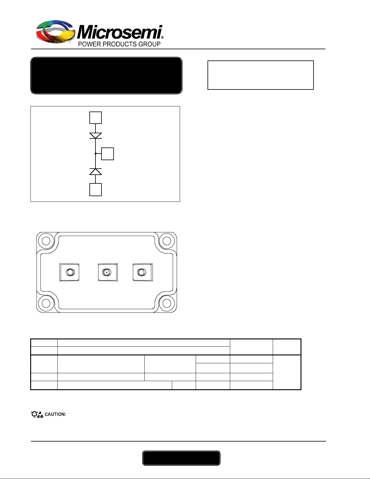
APTDF400KK100G
Dual Common Cathode diodes
Power Module
A1
Application
K
Features
A2
A1 K
Benefits
A2
Absolute maximum ratings
Symbol Parameter Max ratings Unit
VR Maximum DC reverse Voltage
V
Maximum Peak Repetitive Reverse Voltage
RRM
I
F(A V)
I
F(RMS)
I
FSM
These Devices are sensitive to Electrostatic Discharge. Proper Handing Procedures Should Be Followed. See application note
APT0502 on www.microsemi.co m
Maximum Average Forward
Current
RMS Forward Current Duty cycle = 50% TC = 45°C 500
Non-Repetitive Forward Surge Current 8.3ms
Duty cycle = 50%
V
= 1000V
RRM
IC = 400A @ Tc = 70°C
• Uninterruptible Power Supply (UPS)
• Inductio n heati ng
• Welding equipment
• High speed rectifiers
• Ultra fast recovery times
• Soft recovery characteristics
• High blocking voltage
• High current
• Low leakage current
• Very low stray inductance
- Symme trical design
- M5 power connectors
• High level of integration
• Outsta nd i ng perfor ma nce at hi gh freq uenc y
operation
• Low losses
• Low noise switching
• Direct mounting to heatsink (isolated package)
• Low junction to case thermal resistance
• RoHS Compliant
1000 V
TC = 25°C 500
TC = 70°C 400
TC = 45°C
3000
A
www.microsemi.com
1 - 4
APTDF400KK100G – Rev 1 June, 2006
APTDF400KK100G
All ratings @ Tj = 25°C unless otherwise specified
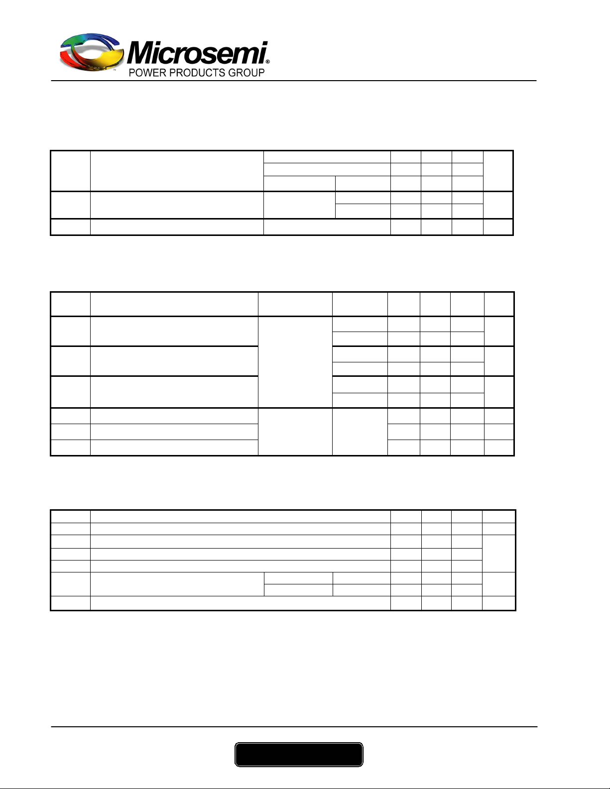
Electrical Characteristics
Symbol Characteristic Test Conditions Min Typ Max Unit
IF = 400A 2.1 2.7
IF = 600A 2.3 VF Diode Forward Voltage
IF = 400A Tj = 125°C 1.7
IRM Maximum Reverse Leakage Current VR = 1000V
CT Junction Capacitance VR = 1000V 480 pF
Tj = 25°C 250
Tj = 125°C 1000
Dynamic Characteristics
Symbol Characteristic Test Conditions Min Typ Max Unit
trr Reverse Recovery Time
trr Reverse Recovery Time
Qrr Reverse Recovery Charge
I
Reverse Recovery Current
RRM
trr Reverse Recovery Time 160 ns
Qrr Reverse Recovery Charge 28.4 µC
I
Reverse Recovery Current
RRM
IF=1A, VR=30V
di/dt = 400A/µs
IF = 400A
VR = 667V
di/dt = 800A/µs
IF = 400A
VR = 667V
di/dt = 4000A/ µs
Tj = 25°C 45 ns
Tj = 25°C 290
Tj = 125°C 340
Tj = 25°C 2.7
Tj = 125°C 14.6
Tj = 25°C 24
Tj = 125°C 72
Tj = 125°C
280 A
Thermal and package characteristics
Symbol Characteristic Min Typ Max Unit
R
Junction to Case 0.14 °C/W
thJC
V
RMS Isolat ion Voltage, any terminal to case t =1 min, I isol<1mA, 50/60Hz 2500 V
ISOL
TJ Operating junction temperature range -40 175
T
Storage Temperature Range -40 125
STG
TC Operating Case Temperature -40 100
Torque Mounting torque
Wt Package Weight
To heatsink M6 3 5
For terminals M5 2 3.5
280
V
µA
ns
µC
A
°C
N.m
g
www.microsemi.com
2 - 4
APTDF400KK100G – Rev 1 June, 2006

Typical Performance Curve
0.16
0.14
0.12
0.08
0.06
0.04
0.02
Thermal Impedance (°C/W)
Maximum Effective Transient Thermal Impedance, Junction to Case vs Pulse Duration
0.9
0.7
0.1
0.5
0.3
0.1
0.05
0
0.00001 0.0001 0.001 0.01 0.1 1 10
APTDF400KK100G
Single Pulse
Rectangular Pulse Duration (Seconds)
Forward Current vs Forward Voltage
1200
1000
800
600
400
, Forward Current (A)
F
200
I
0
0.0 0.5 1.0 1.5 2.0 2.5 3.0
V
, Anode to Cathode Voltage (V)
F
QRR vs. Current Rate Charge
36
TJ=125°C
32
=667V
V
R
28
TJ=175°C
TJ=125°C
600 A
24
20
16
12
, Reverse Recovery Charge (µC)
RR
8
Q
0 800 1600 2400 3200 4000 4800
-diF/dt (A/µs)
TJ=-55°C
TJ=25°C
400 A
200 A
Trr vs. Current Rate of Charge
400
350
300
250
200
150
100
50
, Reverse R ecovery Time (ns)
rr
0
t
0 800 1600 2400 3200 4000 4800
-diF/dt (A/µs)
IRRM vs. Current Rate of Charge
320
TJ=125°C
280
V
=667V
R
240
200
160
120
80
, Reverse Recovery Current (A)
40
RRM
I
0 800 1600 2400 3200 4000 4800
-diF/dt (A/µs)
600 A
TJ=125°C
V
=667V
R
600 A
400 A
200 A
400 A
200 A
Capacitance vs. Reverse Voltage
3200
2800
Max. Average Forward Current vs. Case Temp.
600
500
Duty Cycle = 0.5
T
=175°C
J
2400
2000
1600
1200
800
C, Capacitance (pF)
400
0
1 10 100 1000
VR, Reverse Voltage (V)
400
300
(AV) (A)
F
I
200
100
0
0 25 50 75 100 125 150 175
Case Temperature (ºC)
www.microsemi.com
3 - 4
APTDF400KK100G – Rev 1 June, 2006

SP6 Package outline (dimensions in mm)
APTDF400KK100G
M icros e mi rese rve s the right to c ha ng e , wi tho ut notice , the s pe cificatio ns and i nfo rmatio n conta i ne d herein
Microsemi's products are covered by one or more of U.S patents 4,895,810 5,045,903 5,089,434 5,182,234 5,019,522
5,262,336 6,503,786 5,256,583 4,748,103 5,283,202 5,231,474 5,434,095 5,528,058 and foreign patents. U.S and Foreign patents pending. All Rights Reserved.
www.microsemi.com
4 - 4
APTDF400KK100G – Rev 1 June, 2006
 Loading...