

Microsemi Actel IGLOO Icicle Quick Start Manual

IGLOO Icicle Kit
Quick Start Guide
1. How to Start the demo
1.1. Upon power up, the display will default to a random pattern.
1.2. To display the message associated with the default design
shipped with the Icicle Kit:
1.2.1. Push SW1 to reset the board
1.2.2. Then press SW5 to enable and initialize the display.
1.2.3. The message ACTEL IGLOO will be displayed.
1.2.4. If this message is not displayed or flickers badly, the board
may have a manufacturing test design installed. In this case,
simply reprogram the board with the STAPL file included on the
IGLOO Icicle Kit CD.
1.3. To cause display to scroll continuously:
1.3.1. Push SW5 a second time. Further presses of SW5 will have
no affect on the display.
1.4. Once the message is scrolling, pushing SW1 will reset the board
and freeze the message.
1.5. To re-initialize the display, push SW5 once and to re-activate
the scroll, push SW5 a second time.
1.6. If the Flash*Freeze mode is initiated while the display is active,
the display retains its current state. At this point, the FPGA is no
longer driving the display. Since the information has already been
written to the OLED assembly, the display will continue to show
the same message. Upon exiting the Flash*Freeze mode, the display
will also retain its current state and function as described above.
1.6.1. In Flash*Freeze, the Current Sense LED will turn on to
show Low Current Mode.
1.6.2. The LED counter design will stop and restart from the same
count when it comes out of F*F
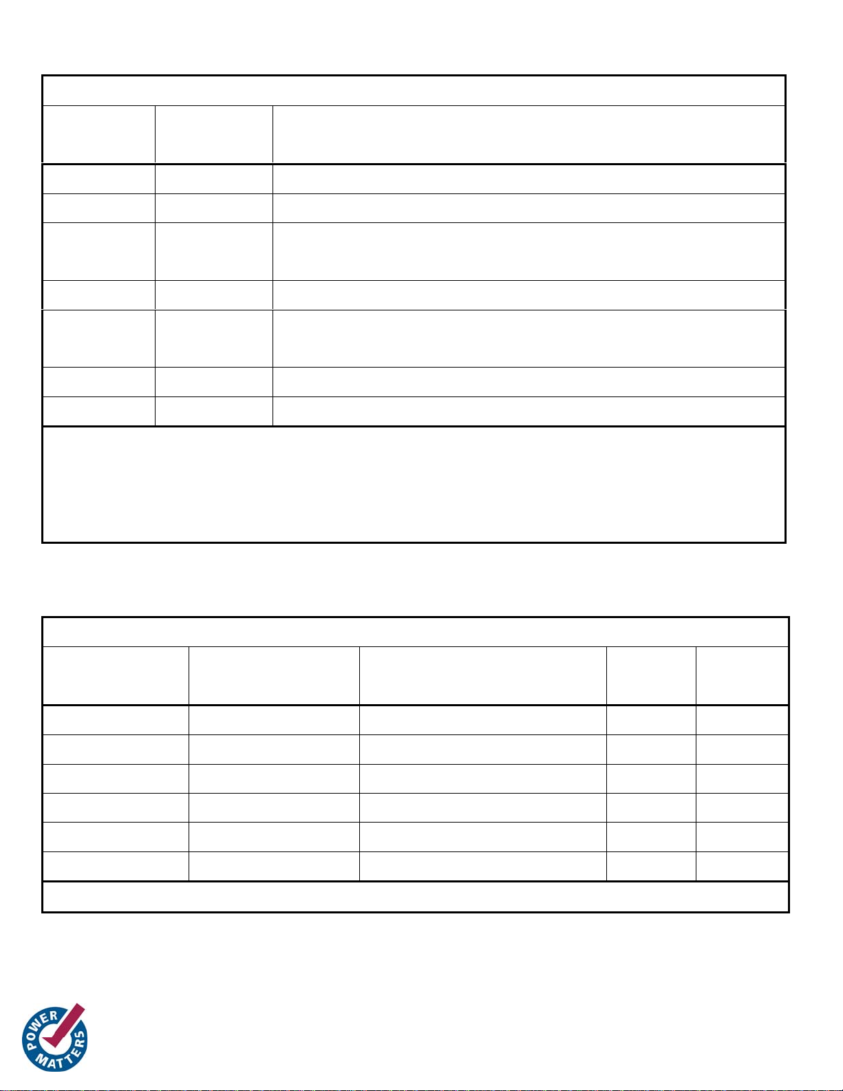
Table of Default Jumper Settings and Current measurement
Jumper Default
Comment
Position
JP2 (1, 2) Power for VCC, current measurement ok
JP3 (1, 2) 3.3V Power for V
, current measurement ok
CCI
JP4 (2, 3) Flash*Freeze from SW3; position (1, 2) is for
internal Flash*Freeze (mode 2)
JP5 Empty External power source can be applied here
JP9 (2, 3) VCC is 1.2V except in programming; position (1,
2) fixes V
JP10 (1, 2) Applies power to V
CC
CCPLF
JP11 (1, 2) Vertical orientation for battery and USB power
Do not connect a DMM across pins (1, 2) of JP11 for current
measurement as the USB Change over circuit is sensitive to inductance.
Better to connect an external 5V supply to JP5 and then put a DMM in
current mode across (2, 3) for measuring board power.
Table for User Peripherals
Peripheral Comment AGL125 I/O Name Pin on
QN132
Pin on
VQ100
D1 LED IO96RSB1 A17 33
D2 LED IO95RSB1 B16 34
D3 LED IO94RSB1 A18 35
SW1 Reset Switch GAA2/IO67RSB1 C1 2
Clock 20MHz GFB0/IO123RSB1 A7 11
Flash*Freeze SW3 and JP4 FF/GEB2/IO105RSB1 B12 27
For other peripherals and details on the interface card, see the User Guide
 Loading...