

Microsemi 9501G/48VDC User Manual
Safety Information
Important Safety Information
♦ Install ation and removal of the PoE Midspan must be
carried out only by qualified personnel.
♦ Only an isol ated AC/DC power source should be used
to power up the POE Midspan.
♦ The external power supply for t he equipment will be a
listed, direct plug in power unit, marked Class 2, or
listed ITE power supply, marked LPS, which has
suitably rated output voltage and current.
♦ DC Power Inlet:
The power connector supplied with the PoE Midspan
(included in the package) has 2 terminals; '+' (POS)
and '-' (NEG) (See Figure 2).
The power inlet cables (not included in the package)
must be rated for current capacity of 2 Amperes
(Stranded
tinned copper 16 AWG for each terminal).
Before connecting power inlet cables t o the connector
terminals verify that the power source is off.
After inserting a cable inlet to the connector terminals,
tightly fasten all 4 connector screws (See Figure 2).
This clause is optional:
For improved EMI performance, connect chassis
ground connection to "Earth/Ground" connection at
the working area.
There is no safety hazard when the chassis ground
connection is not connected to the "Earth/Ground".
The PoE Midspan "DATA IN" and "DATA & POWER OUT"
ports are shielded RJ45 data sockets. They cannot be used
to connect telephone wiring. Only RJ45 data connectors
can be connected to these sockets.
The DC power source should be situated near the PoE
Midspan and easily accessible. To disconnect the power
from the PoE Midspan, disconnect the DC power cord from
either the DC power source or from the PoE Midspan power
connector.
The PoE Midspan “DATA IN” and “DATA & POWER OUT”
interfaces are qualified as SELV (Safety Extra-Low Voltage)
circuits according to IEC 60950-1. These interfaces can be
connected only to SELV interfaces of other equipment.
WARNINGS:
• Before connecting the PoE Midspan to its power source,
read the installation instructions.
• Whenever connecting the PoE Midspan to its power source,
follow basic electricity safety measures.
• A voltage mismatch can cause equipment damage and may
pose a fire hazard. If the voltage indicated on the label is
different from the power outlet voltage, do not connect the
PoE Midspan to this power outlet.
• Take extra care when connecting the power inlet
terminals, so that '+’ (POS) and '-' (NEG) terminals are
connected to the proper polarity.
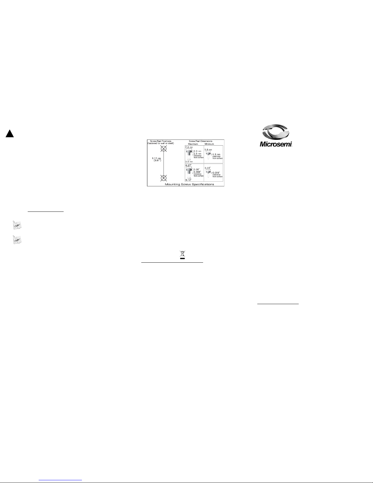
Mounting Instructions
Perform the following instructions:
1. Install two screws in the wall or shelf as shown in Figure 1.
Figure 1: PoE Midspan mounting instructions
2. Align the PD-9501G/48VDC mounting slots to capture the surface
screws.
Recycling and Disposal
Disposal instructions for old product: The WEEE (Was te Electrical &
Electronic Equipment) national environment al initiatives has been put
place to ensure that products are recycled using the bes t available
treatment, recovery and recy cling techniques so that human health
and environmental protection considerations receive maximum
attention. This product is designed and manufactured with high
quality materials and components, which can be recycled and
reused.
Do not dispose your old product in a general house hold waste bin.
Inform yourself about your local separate collection system for
electrical and electronic products, marked by thi s symbol:
Use one of the following disposal options :
1. Dispose of the complete product (including its cables, plugs and
accessori es) in a WEEE designated collection facility.
2. If you purchase a replacement product, hand your complete old
product over to the retailer. He should accept it as requ ired by the
national WEEE legislation.
Microsemi Corp.
• Microsemi name & logo are registered trademarks of Microsemi
corp.
• 802.3at is a trademark of IEEE.
Ordering information:
• Product Name: Microsemi 9501G/48VDC
• Part Number: PD-9501G/48VDC
• Description: 1-Port 802.3at 4-Pairs Gigabit PoE Midspan,
48VDC input
Document P/N PD-9501G-48VDC_UG Rev. C00
Microsemi 9501G/48VDC
1BUser Guide
2B1-Port 802.3at
TM
4-Pairs Gigabit
PoE Midspan, 48VDC input.
It is Microsemi’s polic y to improve its products as new technology,
components, software, and firmware become available. Microsemi
therefore, reserves the right to change specifications without prior
notice.
Notice
Technical Support
If you encounter problems when installing or using this product,
please consult the Microsemi website at:
http://www.microsemi.com
For technical support, call: +972-9-775-5123
In the USA: 1-877-480-2323
Email: sales.support@microsemi.com
Functions and Features
The high-power gigabit single port PoE (Power over Ethernet)
PD-9501G/48VDC Midspan injects power over data-carrying Ethernet
cabling. It maintains the IEEE802.3at and IEEE802.3af standard, while
doubling the output p ower (60W). These power lev els allow usage by a
new range of Ethernet-based applicati ons such as Video P hones, 80 2.11n
access Points, WiMAX
TM
Transmitters, PTZ Cameras & more. The
PD-9501G/48VDC "DATA & POWER OUT" port is designed to carry
Gigabit Ethernet dat a & pow er over a stan dard CA T5/5e/6 cable, delive red
through all 4-pairs
EMC Compliance:
• FCC Part 15 class B
• EN55022 class B
• EN55024
Safety compliance:
♦ UL60950-1
♦ GS compliance
Preliminary Steps
• Ensure DC pow er is applied t o the PoE Midspan, using stranded tinned
copper 16 AWG cables for each t erminal (r ated for 2 Amper es), with an
appropriate separate ground connection (when needed).
• Ensure that the output Ethernet c able is connected to the "DATA &
POWER OUT" port.
• Verif y that an Ethernet compatible d evice is connected to the outpu t
Ethernet cable, and that i t is arranged to r eceive power on its Ethernet
port.
WARNING
Do not use a cross over cable between the PoE Midspan output port and the
load device.
Installation
The PoE Midspan may be l ocated on a desktop/ floor or mount ed on a
wall/bench using the rear side mounting holes.
• Associated Ethernet wiring shall be limited to inside of the building
• Power inlet cable and chassis conne ction cable are not supplied wit h the
product
: Before mounting the PoE Midspan to a fixed location:
• Make sure the PoE Midspan and the airflo w to it, are not covered or
blocked by any foreign objects. Keep the PoE Midspan away from
excessive heat and humidit y and ensure it is free from vibration and
dust.
• Ensure that the total Ethernet cable length does not exceed 100 met ers
(333 feet). The PoE is not a repeater and does not amplify the Eth ernet
data signal.
• A splitter may be used if desired ; ensure that the spli tter is connected
close to the PD but not to the Mids p an.
• There is no “On-Off” switch; simply plug the PoE Midspan into a DC
power source.
Installing the Unit
• Verify that DC power source is off.
• If supplemental earth ground is replaced, apply 5Lb/In torque (optional).
• Tighten the 2 connector screws (see Figure 2).
• Connect the PoE Midspan PWR connector to stranded tinned copper
cables, 16 AWG for each termin al (rat ed for 2 Amperes), and tighten the
2 Cable inlet screws (See Figure 2).
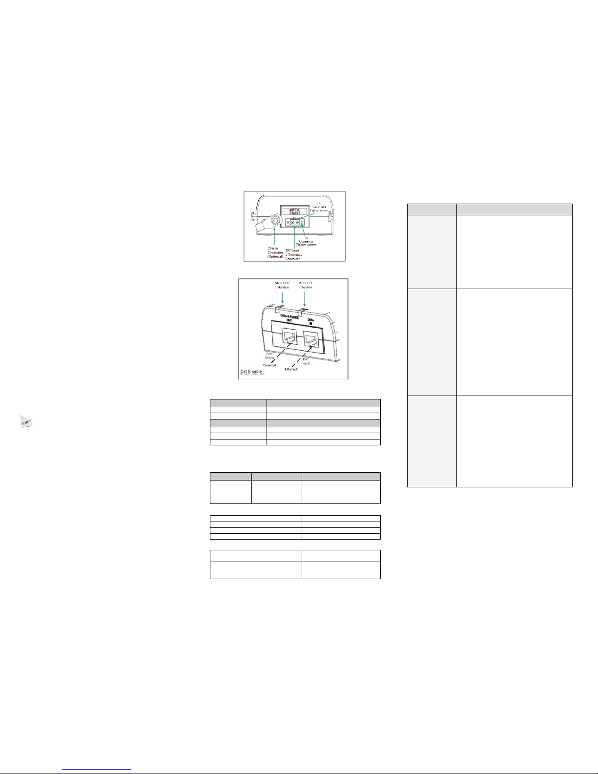
• Connect the “DATA IN” jack (input) to the data source (s witch) and the
“DATA & POWER” jack (output) to the t erm i nal (P D) (See Figure 3).
• Turn on the DC power source and ch eck the app ropriat e LED indica tors
to verify that power is on
•
Figure 2: PoE Midspan Power Connector
Figure 3: PoE Midspan Ports
Indicators
Main LED Behavior
OFF
Power OFF indication
Green on Power ON indication (power is active)
Port LED Behavior
OFF Disconnection, or no detection, or no load is connected.
Green on
Power supplied over data and spare pairs
Blinking green at 1Hz rate
Overloaded / shorted
13BSpecifications
16BEnvironmental Specifications
Mode Temperature Humidity
Operating
-20 to 40°C
-4 to 104°F
10 to 90%
(no condensation allowed)
Storage
-20 to 70°C
-4 to 158°F
10 to 90%
(no condensation allowed)
14BElectrical Specifications
Operation Voltage
36-60VDC
Input Current (max.) 2 Amperes
Available Output Power (max.)
60 Watts
Nominal Output Voltage 53.5 to 55.5VDC
17BEthernet Interface
Input (DATA IN):
Ethernet 10/100/1000Base-T
RJ45 female socket
Output (DATA & POWER OUT):
Ethernet 10/100/1000Base-T,
plus 55VDC
RJ45 female socket, with DC voltage
on wire pairs 1-2, 3-6, 4-5 & 7-8.
Troubleshooting
Symptom Corrective Steps
PoE Midspan
does not
power up
1. Ensure that the installation was in
accordance with the "Installing the
Unit" section in this user guide.
2. Ensure that the power source
supplies between 36-60VDC and can
carry out 80W.
3. Remove and re-apply power to the
PoE Midspan, and verify that the main
led indicator on the front panel is
continuously lit.
The PD
(Powered
Device)
does not
operate
1. Check the Midspan’s LED indicators.
2. Remove and re-apply power to the
PoE Midspan, and check the led
indicators during power up sequence.
3. Verify that the PD is designed for PoE
operation.
4. Verify that you are using a standard
UTP/FTP category 5/5e/6, straightwired four pairs cable.
5. Verify that the PD is connected to the
"DATA & POWER OUT" port.
6. If an external po wer splitter is in use,
replace it with a splitter known as
good.
The end device
operates,
but there is
no data link
1. Verify t hat the port LED indicator on
the front panel is continuously lit.
2. Verify that you are using a standard
UTP/FTP Category 5/5e/6, straightwired cable.
3. Verify that the Ethernet cable length is
less than 100 meters from the POE
source to PD.
4. Ensure that the input Ethernet cable
is connected to the "DATA IN" port.
5. If a spl itter is in use, replace it with a
splitter known as good.
 Loading...