

Page 1
Safety Information
Stud diameter = 5 mm
Connect this side
To earth ground
Stud diameter = 5 mm
Recycling and Disposal
Use one of the following disposal options :
Document P/N 06-0062-056 Rev. C00
Important Safety Information
♦ Installation and removal of the PoE Midspan must be
carried out by qualified personnel only.
♦ AC Power Cord Set:
o The power cord must have regulatory agency
approval for the specific country in which it is being
used (i.e., UL, CSA, VDE, etc.).
o The power cord must be a three-conductor type
(two current carrying conductors; one ground
conductor) terminated on one end by an IEC 60320
appliance coupler (for connection to the PoE
Midspan), and on the other end by a plug containing
a ground (earthing) contact.
o The power cord must be rated for a minimum of
250Vac RMS operation, with a minimum rated
current capacity of 5 Amps (or a minimum wire
gauge of 18 AWG (0.75mm2).
: PoE Midspans installed in Australia require power
cords with a minimum wire gauge of 16 AWG (1.0 mm2).
: The PoE injector "Data In" and "Data & Power Out"
ports are shielded RJ45 data sockets. They cannot be used as
Plain Old Telephone Service (POTS) telephone sockets. Only
RJ45 data connectors may be connected to these sockets.
o The AC wall socket-outlet must be near the PoE
Midspan and easily accessible. You can remove AC
power from the PoE Midspan by disconnecting the
AC power cord from either the wall socket-outlet or
the PoE Midspan appliance coupler.
o The PoE Midspan Data In and Data & Power Out
interfaces are qualified as SELV (Safety Extra-Low
Voltage) circuits according to IEC 60950-1. These
interfaces can only be connected to SELV
WARNINGS!
♦ Read the installation instructions before connecting the
♦ Follow basic electricity safety measures whenever
♦ A voltage mismatch can cause equipment damage and
♦ The equipment is intended only for installation in a
interfaces on other equipment.
PoE Midspan to its power source.
connecting the PoE Midspan to its power source.
may pose a fire hazard. If the voltage indicated on the
label is different from the power outlet voltage, do not
connect the PoE Midspan to this power outlet.
Restricted Access Location/
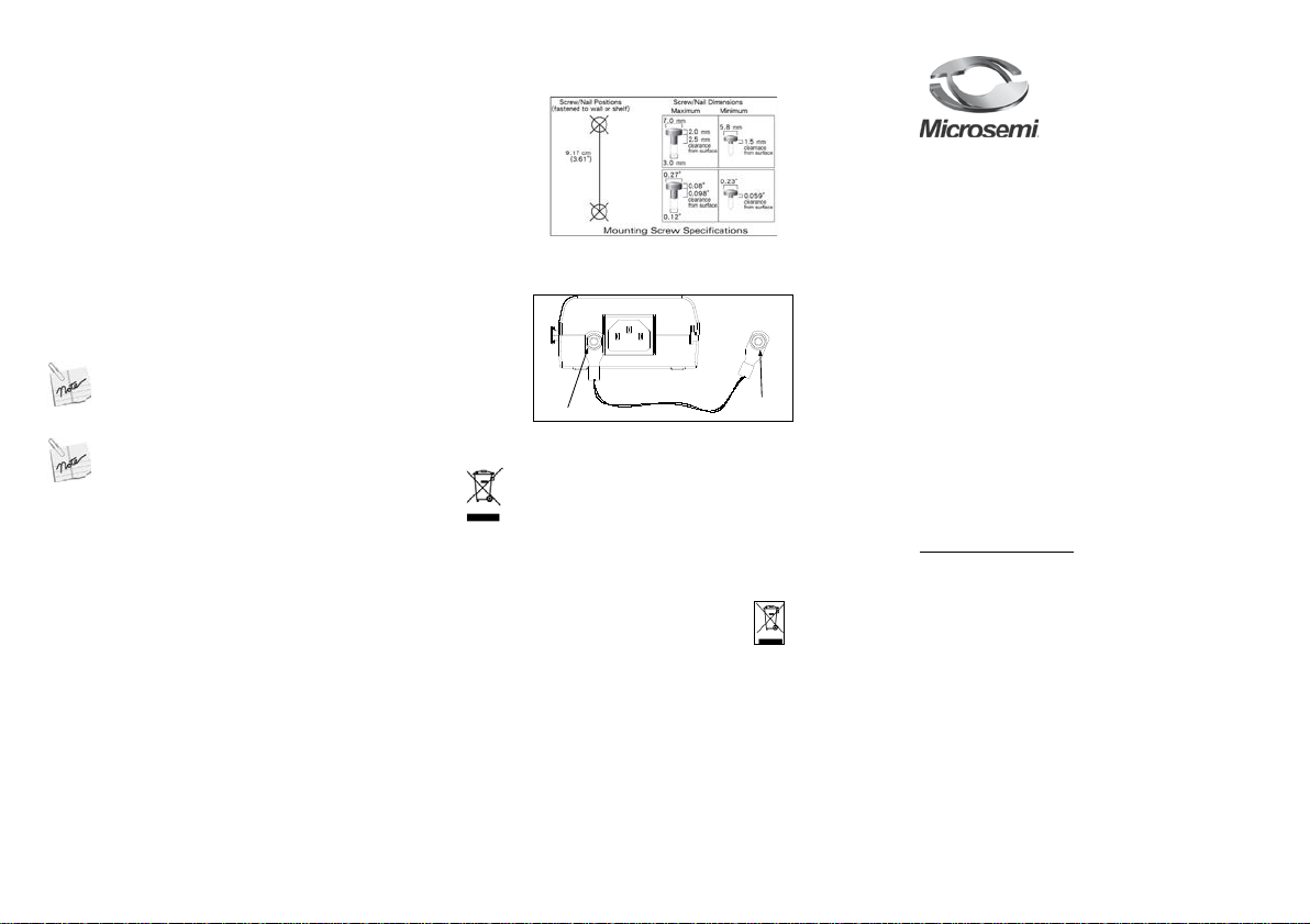
Mounting Instructi ons
Perform the following:
1. Install two screws in the wall or shelf as shown below:
2. Align the unit's mounting slots to capture the surface screws
3. Connect the ground studs as shown below:
Ordering info rmation:
• Product Name: Microsemi 9001G-40/SP
• Part Number: PD-9001G-40/SP/AC
• Description: 1-Port 802.3at 40W Gigabit PoE Midspan with
Surge Protection
Figure 1: Mounting Instructions
Figure 2: Stud Connection to Ground
Disposal instructions for old product s. The WEEE (Waste Electrical
and Electronic Equipment) national env ir onm ental initiatives has
been put in place to ensure that products are recycled using best
available treatment, recovery and r ecycling techniques to ensure
human health and high environmental prot ection. Your product is
designed and manufactured with high quality materials and
components, which can be recycled and reused. Do not dispose of
your old product in your general household waste bin. Inform
yourself about the local separate collection system for electrical and
electronic products marked by this symbol:
1. Dispose of the complete product (including its cables, plugs
and accessories) in the designated WEEE collection facilities.
2. If you purchase a replacement product, hand your complet e
old product back to the retailer. He should accept it as required
by the national WEEE legislation.
MMiiccrroosseemmii 99000011GG--4400//SSPP UUsseerr
GGuuiiddee
11--PPoorrtt 880022..33aatt 4400WW GGiiggaabbiitt PPooEE
MMiiddssppaann wwiitthh SSuurrggee PPrrootteeccttiioonn
Notice
It is Microsemi’s policy to improve its products as new
technology, components, software, and firmware
become available. Microsemi, therefore, reserves the
right to change specifications without prior notice.
Technical Support
If you encounter problems when installing or using this
product, please consult the Microsemi website at:
http://www.microsemi.com
For technical support, call: +972-9-775-5123
In the USA: 1-877-480-2323
Email: sales.support@microsemi.com
Microsemi Corp.
Covered under one or more of US Patents:
#7,006,815; and 7,437,217.
Page 2
Functions and Features
Ethernet
Cat . 5 Cable
Terminal
Port Connectivity
Indication
AC Input
Connectivity
Indicator
at 1 Hz
at 4 Hz
Internal Fault
Operating
0 to 40°C
10 to 90%
allowed)
Storage
-20 to 70°C
10 to 90%
allowed)
Maximal Available Output Power
40 Watts
Nominal Output Voltage
52 to 56 VDC
Ethernet 10/100/1000Base-T
socket
Output (Data & Power Out):
RJ45 female
5.
during power up sequence.
1. Verify that Midspan detects a
RJ45 connection.
The High-Power Gigabit single port PoE (Power over Ethernet) PD9001G-40/SP Midspan injects power over data-carrying Ethernet
cabling. It supports the IEEE802.3at and IEEE802.3af standards,
while increasing the output power to 40W. These power levels allow
usage by a new range of Ethernet-based applications such as Video
Phones, 802.11n Access Points, WiMAX Transmitters, PTZ Cameras
& more. The PD-9001G-40/SP Data & Power Output port is designed
to carry Gigabit Ethernet data & power over a standard CAT5e cable,
delivered through all 4-pairs (Alt A: pins 1,2 (-) & 3,6 (+), Alt B: 4,5 (+)
and 7,8 (-)).
PD-9001G-40/SP EMC Compliance:
♦ FCC Part 15 class B and EN55022 class B
♦ EN55024
♦ VCCI
PD-9001G-40/SP Safety Compliance:
♦ UL/cUL per EN60950-1
♦ GS mark
PD-9001G-40/SP Lightning Protection:
♦ Designed to meet GR-1089-CORE lightning protection demands.
Preliminary Step s
♦ Ensure that AC power is applied to the PoE Midspan, using an
♦ Ensure that output Ethernet cable is connected to the Data&
♦ Verify that power ready Ethernet compatible device is connected.
WARNING
Do not use cross over cable between the PoE Midspan output port and the load device Installation The PoE Midspan may be located on a desktop or wall/bench mounted using the rear side mounting holes.
♦ Do not to cover PoE Midspan or block the airflow to the PoE
♦ Ensure that the cable length from Ethernet network source to
♦ Use a splitter if desired; ensure that the splitter is connected
♦ No “on-off” switch exists; simply plug the PoE Midspan into an
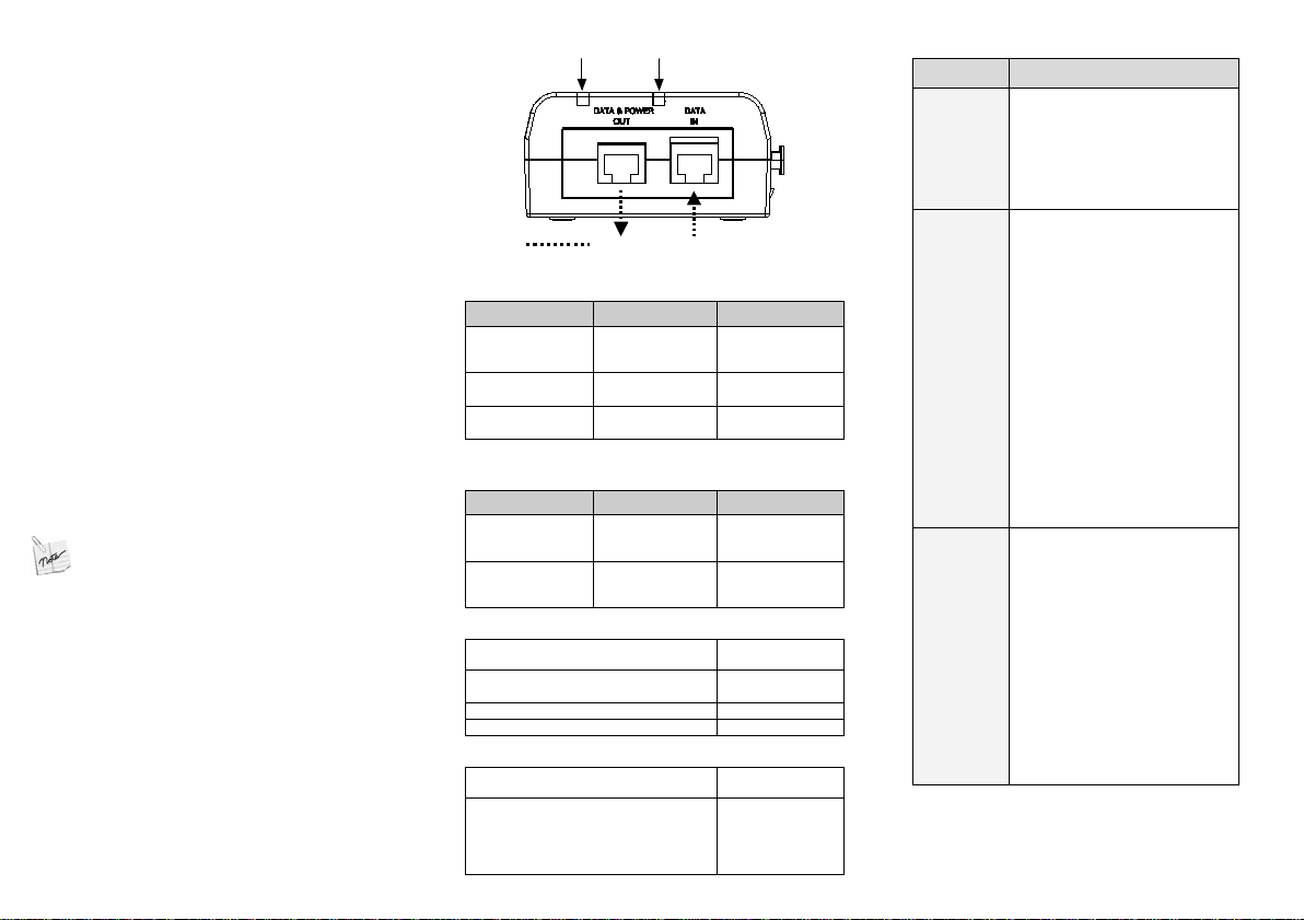
Installing the Unit
1. Connect the PoE Midspan to an AC outlet (100-240VAC) , usi n g a
standard power cord.
2. Connect the Data I n j ack ( input ) to th e r em ote Ethernet network sw i tc h's
Patch panel and the Dat a & P ow er Out j ack ( ou tput ) to the terminal.
3. Connect the chassis screw connection to the main chassis infrastructure
as illustrated on Figure 2.
4. Associated Ethernet wiring shall be limited to inside of the building.
operational AC cable with an appropriate ground connection.
Power Out port.
: Before mounting the PoE Midspan to a fixed location:
with any foreign objects. Keep the PoE Midspan away from
excessive heat and humidity and free from vibration and dust.
the terminal does not exceed 100 meters (333 feet). The PoE
is not a repeater and does not amplify the Ethernet
data signal.
close to the terminal and not on the Midspan!
AC power source.
Indicators
Figure 3: Connecting the PoE Midspan
LED AC (Main) Port
Green
Indicates that the
power is ON
(Power is active)
Green Blinking
Green Blinking
12BSpecifications
15BEnvironmental Specifications
-
-
Indicates that a
remote terminal
is connected
Overload or short
circuit
Condition
Mode Temperature Humidity
32 to 104°F
-4 to 158°F
13BElectrical Specifications
Input Voltage 100-240 VAC
Input Current (110 - 220VAC) 0.8 Ampere
16BEthernet Interface
Input (Data In):
Ethernet 10/100/1000Base-T, plus
55VDC
(no condensation
(no condensation
(50-60 Hz)
(max)
RJ45 female
socket, with DC
voltage on wire
pairs 7-8 and 4-
14BTroubleshooting
Symptom Corrective Steps
Midspan
does not
power up
A port
indicator is
not lit and
the PD
does not
operate
The end
device
operates,
but there is
no data
link
1. Verify that a reliable cord is in
use.
2. Verify that the voltage at the
power inlet is between 100 and
240 Vac.
3. Remove and re-apply power to
the device and check the indicators
PD.
2. Verify that the PD is designed
for PoE operation.
3. Verify that you are using a
standard Category 5/5e/6, straightwired cable, with four pairs.
4. If an external power splitter is in
use, replace it with a known-good
splitter.
Ensure input Ethernet cable is
connected to the Data In port.
5. Verify that the PD is connected
to the Data & Power port.
6. Try to reconnect the same PD
into a different Midspan. If it works,
there is probably a faulty port or
RJ45 connection.
7. Verify that there is no short over
any of the twisted pair cables or
over the RJ45 connectors.
1. Verify that the port indicator on
the front panel is continuously lit.
2. If an external power splitter is in
use, replace it with a known-good
splitter.
3. Verify that for this link you are
using standard UTP/FTP Category
5 straight (non-crossover) cabling,
with all four pairs.
4. Verify that the Ethernet cable
length is less than 100 meters from
the Ethernet source to the
load/remote terminal.
5. Try to reconnect the same PD
into a different Midspan. If it works,
there is probably a faulty port or
 Loading...