

Page 1

Visionscape® Smart Camera
HE1600T Guide
Rev. 1H, Mar 2009
EM-40247-1H
Page 2

Copyright and Disclaimer
Copyright ©2009 by Microscan Systems, Inc.
1201 S.W. 7th Street, Renton, WA, U.S.A. 98057
(425) 226-5700 FAX: (425) 226-8682
All rights reserved. The information contained herein is proprietary and is provided solely for the purpose of allowing
customers to operate and/or service Microscan manufactured equipment and is not to be released, reproduced, or used
for any other purpose without written permission of Microscan.
Throughout this manual, trademarked names might be used. Rather than place a trademark (™) symbol at every
occurrence of a trademarked name, we state herein that we are using the names only in an editorial fashion, and to the
benefit of the trademark owner, with no intention of infringement.
Disclaimer
The information and specifications described in this manual are subject to change without notice.
Latest Manual Version
For the latest version of this manual, see the Download Center on our web site at: www.microscan.com.
Technical Support
For technical support, email: helpdesk@microscan.com.
Microscan Systems, Inc.
1201 S.W. 7th Street
Renton, WA 98057
U.S.A.
Te l: 425 226 5700
Fax: 425 226 8250
helpdesk@microscan.com
Microscan Europe
Te l: 31 172 423360
Fax: 31 172 423366
Microscan Asia Pacific
R.O. Tel: 65 6846 1214
Fax: 65 6846 4641
Microscan Limited Warranty Statement and Exclusions
What Is Covered?
Microscan Systems Inc. warrants to the original purchaser that products manufactured by it will be free from defects in
material and workmanship under normal use and service for a period of one year from the date of shipment. This
warranty is specifically limited to, at Microscan’s sole option, repair or replacement with a functionally equivalent unit
and return without charge for service or return freight.
What Is Excluded?
This limited warranty specifically excludes the following: (1) Any products or parts that have been subject to misuse,
neglect, accident, unauthorized repair, improper installation, or abnormal conditions or operations; (2) Any products or
parts that have been transferred by the original purchaser; (3) Customer mis-adjustment of settings contrary to the
procedure described in the Microscan Systems Inc. owners manual; (4) Upgrading software versions at customer request
unless required to meet specifications in effect at the time of purchase; (5) Units returned and found to have no failure
will be excluded; (6) Claims for damage in transit are to be directed to the freight carrier upon receipt. Any use of the
product is at purchaser’s own risk. This limited warranty is the only warranty provided by Microscan Systems Inc.
regarding the product. Except for the limited warranty above, the product is provided “as is.” To the maximum extent
Page 3

permitted by law, this express warranty excludes all other warranties, expre s s or implied, including but not limited to,
implied warranties of merchantability and. Technical support questions may be directed to: helpdesk@microscan.com
Register your product with Microscan: www .mi croscan.com/register fitness for a particular pu rpose. Microscan Systems
Inc. does not warrant that the functions contained in the product will meet any requirements or needs purchaser may
have, or that the product will operate error free, or in an uninterrupted fashion, or that any defects or errors in the product
will be corrected, or that the product is compatible with any particular machinery.
Limitation of Liability
In no event shall Microscan Systems Inc. be liable to you or any third party for any special, incidental, or consequential
damages (including, without limitation, indirect, special, punitive, or exemplary damages for loss of business, loss of
profits, business interruption, or loss of business information), whether in contract, tort, or otherwise, even if Microscan
Systems Inc. has been advised of the possibility of such damages. Microscan Systems Inc.’s aggregate liability with
respect to its obligations under this warranty or otherwise with respect to the product and documentation or otherwise
shall not exceed the amount paid by you for the product and documentation. Some jurisdictions do not allow the
exclusion or limitation of incidental or consequential damages or limitations on an implied warranty, so the above
limitation or exclusion may not apply to you. This warranty gives you specific legal rights, and you may also have other
rights which may vary from state to state.
Te l: 425.226.5700 | Fax: 425.226 .8250 | helpdesk@microscan.com
Page 4

Page 5

Contents
PREFACE Welcome! xi
Purpose of This Manual xi
Manual Conventions xi
CHAPTER 1
CHAPTER 2 System Components 2-1
Rev. 1H, Mar 2009 Visionscape® Smart Camera HE1600T Guide v
Introduction 1-1
Product Summary 1-2
Features and Benefits 1-3
Applications 1-4
Package Contents 1-4
Visionscape® Smart Camera HE1600T Models 1-5
Effective Frame Per Second & Pipeline Operation Formulas 1-6
Triggering Rules for Single Channel Devices 1-7
Additional Flash & System Memory (HE1600T) 1-8
Identifying Which Smart Camera Y o u Have 1-9
Jobs & Storage in Non-Volatile Memory 1-10
Basic Components 2-1
Page 6

Contents
Visionscape® Smart Camera HE1600T 2-2
TCP/IP Port Connectivity 2-2
Serial Port Connectivity 2-4
Front P anel 2-5
Rear Panel 2-5
Mode/Status LEDs 2-6
Important Label Information 2-7
Power-on Sequence 2-8
Error Codes 2-8
Beeper 2-9
Mounting & Wiring the Visionscape® Smart Camera HE1600T 2-9
Mounting Using Front Block 2-9
Mounting Using Standard Mounting Block 2-10
Mounting Using Accessory Mounting Block 2-11
Location for Backward Compatible Mounting Block 2-11
Field I/O Wiring Examples 2-12
Input Opto Wiring 2-12
Output Opto Wiring 2-13
External Strobe & Sensor 2-16
Power Requirements 2-16
Power Supply Wiring 2-16
CHAPTER 3
Ethernet/IP Communications 3-1
A/B Logix PLCs That Support Ethernet/IP I/O Messaging 3-2
Ethernet/IP IO Points 3-3
Binary Data Block 3-3
User Data Block Accessor Perl Tools 3-7
BinaryBlockRead/Write Perl Scripts 3-8
Example Ethernet/IP Read/Write Test 3-13
vi Visionscape® Smart Camera HE1600T Guide Rev. 1H, Mar 2009
Page 7

CHAPTER 4 Visualization HMIs 4-1
Settings Pages 4-4
Layout Options 4-5
Modes 4-7
Image Display 4-8
Buttons 4-9
Counters & Status 4-10
Extras 4-11
Report Tab & Setup Screen 4-13
Style 4-16
URL Tab 4-17
Miscellaneous Points 4-17
Displaying the Output of a Datum 4-18
Copying a Symbolic Name to the Clipboard 4-18
Pasting a Symbolic Name into the Report 4-19
Adding Options to the Base URL 4-21
Basic Options 4-21
CHAPTER 5 Optics & Lighting 5-1
Contents
Optics (1610T Only) 5-2
Lighting Connector 5-3
APPENDIX A
Connector Pinouts A-1
Visionscape® Smart Camera HE1600T Connectors A-1
Power & Primary I/O Connector A-1
Serial & Secondary I/O Connector A-3
Ethernet Connector A-4
Light Port Connector A-5
QuickSet® Switch A-7
APPENDIX B Cable Specifications B-1
HETPC-100 - Power & Primary I/O Cable B-1
HETAC-100 - Serial & Secondary I/O Cable B-2
HETENET-XXX - Ethernet Cable B-4
HETLC-050 - Lighting Control Cable B-4
Rev. 1H, Mar 2009 Visionscape® Smart Camera HE1600T Guide vii
Page 8

Contents
APPENDIX C Specifications C-1
Dimensions C-3
APPENDIX D
Setting Up Network Communications D-1
Visionscape® Smart Camera HE1600T Connection Matrix D-3
Visionscape® Smart Camera HE1600T Boot Parameters D-4
Changing Network Parameters D-4
APPENDIX E Updating Firmware on 1600T Cameras E-1
Updating the Firmware with Smart Camera Update E-1
Updating the Firmware with the Bootloader E-3
Main Menu Items E-7
Modify User Parameters E-7
Reset User Account E-8
Exit to Application E-8
Error Codes E-9
APPENDIX F
Ethernet/IP Communication with ControlLogix
PLCs F-1
Overview of the System F-2
IO Mapping F-2
Output Assembly Instance 112 F-2
Input Assembly Instance 100 F-3
Programming the Visionscape® Smart Camera HE1600T F-5
Setting Up The Visionscape® Smart Camera HE1600T F-5
Setting Up the Visionscape® Smart Camera HE1600T Job F-6
Acquisition F-6
Data Matrix Tool F-6
Connecting the PLC Output Assembly Data to Visionscape®
Smart Camera HE1600T Datums F-7
Connecting Visionscape® Smart Camera HE1600T Results to the
PLC Input Assembly Data F-11
viii Visionscape® Smart Camera HE1600T Guide Rev. 1H, Mar 2009
Page 9

Setting Up the PLC Program F-18
Configuring the Hardware F-18
Defining Data Types F-23
Add Controller Tags F-26
Add Program Tags F-28
Ladder Logic F-28
Run the Program F-30
Assembly Data F-31
Introduction to an “Assembly” F-31
Assembly Instance 100 (Input) F-31
DINT 0: 32 Bits of Camera VIO F-32
DINT 1: User Defined Tag Value F-32
DINT 2: Camera Status Register F-32
DINT 3: Last Error F-33
DINT 4…19: User Data F-33
Assembly Instance 112 (Output) F-33
DINT 0: 32 Bits of Camera VIO F-33
DINT 1: User defined tag value F-33
DINT 2: Camera Control Register F-34
DINT 3: Reserved F-34
DINT 4…19: User Data F-34
Contents
Index 1-1
Rev. 1H, Mar 2009 Visionscape® Smart Camera HE1600T Guide ix
Page 10

Contents
x Visionscape® Smart Camera HE1600T Guide Rev. 1H, Mar 2009
Page 11

Preface
PREFACE Welcome!
Purpose of This Manual
This manual contains detailed information about the V isionscape® Smart Camera
HE1600T family.
Manual Conventions
The following typographical conventions are used throughout this manual.
• Items emphasizing imp ortant information are bolded.
• Menu selections, menu items and entries in screen images are indicated as:
Run (triggered), Modify..., etc.
Rev. 1H, Mar 2009 Visionscape® Smart Camera HE1600T Guide xi
Page 12

Preface
xii Visionscape® Smart Camera HE1600T Guide Rev. 1H, Mar 2009
Page 13

1
CHAPTER 1 Introduction
1
Introduction
FIGURE 1–1. Visionscape
®
Smart Camera HE1610
Rev. 1H, Mar 2009 Visionscape® Smart Camera HE1600T Guide 1-1
Page 14

Chapter 1 Introduction
Product Summary
The HE1600T, one of our Visionscape® family of networked Smart Cameras,
combines a rugged IP67 smart camera form-factor with the broad applicability,
flexibility, and proven vision toolkit of Visionscape
performance vision boards. Designed for use in a broad range of vision
applications, the Visionscape
easily deployed solution for manufacturers to monitor quality, control processes,
or identify and trace parts on their production lines.
Visionscape
cameras with C-mount optics and separate lighting. Like all other Visionscape
Smart Cameras, the 1600T comes standard with built-in digital I/O, serial
communications, and Ethernet networking. All vision processing is done onboard using a high performance, embedded CPU. A real-time, multitasking
operating system ensures deterministic performance and facilitates integration in
high-speed manufacturing lines.
The Visionscape
vision processing tools, including Data Matrix and bar code reading, optical
character recognition (OCR), image processing, image analysis and feature
extraction, flaw detection, object location, calibrated dimensional measurements,
and various custom processing options. Developed and perfected on prior
generations of our machine vision systems, these tools have already been
successfully applied in thousands of production installations worldwide.
®
Smart Cameras are configured as flexible, general-purpose smart
®
®
, and our line of high
®
Smart Camera HE1600T provides a cost effective,
Smart Camera HE1600T offers an extensive array of built-in
®
Setup of a new vision application to run on the camera is done on a host PC on
the same network using the same powerful graphical application environment as
the rest of the Visionscape
architecture allows running the same vision application program on any
Visionscape
Visionscape
®
Smart Camera HE1600T vision Smart Camera or any
®
vision board, leveraging the end-user’s investment in application
®
line. Our patented Visionscape® step program
development and training.
Scaleability and compatibility with the rest of the Visionscape
Visionscape
®
Smart Camera HE1600T apart from other smart cameras in the
®
family set the
market today. The same point-and-click environment c a n be used to configure
applications deployed on smart cameras and framegrabbers.
The Smart Camera family supports 16 MB of Non-Volatile memory for Kernel
and Job saving (3 MB maximum AVP size) and 64 MB of RAM for operation.
The camera sensor (depending on model) supports acquisitions of:
1-2 Visionscape® Smart Camera HE1600T Guide Rev. 1H, Mar 2009
Page 15

Features and Benefits
• 1024x768 (X GA) images at a maximum rate of 30 frames/sec
• 648x494 (VGA) images at a maximum rate of 60 frames/sec
1
It also supports 8 opto idolated digital IO lines in addition to a dedicated light
connector for controlling and powering an external light (Visionscape
Camera HE1610T configuration only). Partial scan at higher frame rates is
supported.
There is full support for:
• Acquisition m odes, including:
– Exposure (64 usec to 58.8 msec)
– Analog gain (0.1 to 63.0)
– Offset (-255 to +255)
• Visionscape
– 1 trigger
– 1 strobe output
– 3 opto isolated outputs
– 4 additional opto isolated general purpose I/O fully assignable in the
AVP
®
Smart Camera HE1600T I/O:
®
Smart
Introduction
Features and Benefits
• Compact, all-in-one smart camera configuration for ease of integration
• Built-in digital I/O, serial communications and Ethernet networking for open
connectivity to other equipment
• Flexibili ty in lighting and optics selection for broad applicability
• Comprehensive, fully-featured vision processing toolkit
• Graphical environment for fast application development
• No conventional prog ram ming required for setup of complex vision
applications
Rev. 1H, Mar 2009 Visionscape® Smart Camera HE1600T Guide 1-3
Page 16

Chapter 1 Introduction
• Scaleability and full compatibility with Visionscape® board line allows
leveraging user training and application development investment
Applications
• Part presence/absence
• Assembly verification
• Inspection
•Gauging
• Part location/orientation detection
• Alignment/ guidance
• Automatic ID (Data Matrix, bar code, OCR)
Package Contents
Before you install Visionscape® software and mount, wire, and connect your
Visionscape
package contains the following items:
• Visionscape
four available Smart Camera models (see Table 1–1).
• CD — Your CD contains Vi sionscape
1-4 Visionscape® Smart Camera HE1600T Guide Rev. 1H, Mar 2009
®
Smart Camera HE1600T , please take a m oment to co nfirm t hat the
®
Smart Camera HE1600T — Yo ur package contains one of
®
software and all documentation.
Page 17

Visionscape® Smart Camera HE1600T Models
Visionscape® Smart Camera HE1600T Models
T able 1–1 lists and describes the Visionscape® Smart Camera HE1600T models,
including acquisition modes and resolutions.
1
TABLE 1–1. Visionscape
Number Model Resolution
GMV-0HT16-0CM0G HE 1610TS
GMV-1HT16-0CM0G HE 1610TH
GMV-0HF16-0CM0G HE 1610TIS
GMV-1HF16-0CM0G HE 1610TIH
®
Smart Camera HE1600T Models & Resolutions
FullScan: 648x494
(Standard Resolution)
PartialScan:Half: 648x227
Quarter: 648x81
Binning:324x242
FullScan: 1024x768
(High Resolution)
PartialScan:Half: 1024x344
Quarter: 1024x137
Binning:512x370
(Standard Resolution w/IntelliFind)
(High Resolution w/IntelliFind)
FullScan: 648x494
PartialScan: Half: 648x227
Quarter: 648x81
Binning:324x242
FullScan: 1024x768
PartialScan: Half: 1024x344
Quarter: 1024x137
Introduction
Binning:512x370
The Visionscape
®
Smart Camera HE1600T supports up to a maximum of four
inspections.
Rev. 1H, Mar 2009 Visionscape® Smart Camera HE1600T Guide 1-5
Page 18

Chapter 1 Introduction
Effective Frame Per Second & Pipeline Operation Formulas
Use the following formula to calculate effective FrameRatePerSecond in a
Visionscape
EFPS = ----------------------------------------------------------------------------------------------------
Where VS Overhead is typically:
Interrupt Latency + Framework Overhead = 0.5 msec max
Or
EFPS = -----------------------
In Ta ble 1–2, EFPS is given in PowerStrobe with 1msec Integration time and Job
in full pipeline, meaning that the Job tools + idle processing time, i.e., less than
(IT + VFT + 0.5) above.
®
Job:
(IT IntegrationTime + VFT VendorFrameTime + VSO VS Overhead) in msec
1000.0
(IT + VFT + 0.5)
1000.0
Full Pipeline = (AVT AVP Processing Time + IDT Inspection Idle Time +
LossLess Connection Overhead) < (IT + VFT + VSO) idle time is defaulted to
3% of the Inspection Time as defined in the VisionSystemStep property page.
Table 1–2 lists Visionscape
®
Smart Camera HE1600T models, modes, and
frames per second.
1-6 Visionscape® Smart Camera HE1600T Guide Rev. 1H, Mar 2009
Page 19

Visionscape® Smart Camera HE1600T Models
1
TABLE 1–2. Visionscape
Model Mode
HE1610TS
HE1610TIS
(Standard)
HE1610TH
HE1610TIH
(High Res)
Full [64 - 50000] 55 60 648x494 Progressive
1/2 [64 - 50000] 102 120 648x227 Progressive
1/4 [64 - 50000] 176 240 648x81 Progressive
Pixel Add [64 - 50000] 102 120 324x242 Progressive
Full [90 - 50000] 28.7 30 1024x768 Progressive
1/2 [90 - 50000] 55 60 1024x344 Progressive
1/4 [90 - 50000] 102 120 1024x137 Progressive
Pixel Add [90 - 50000] 55 60 512x370 Progressive
®
Smart Camera HE1600T Modes, Ranges, & FPS
Exposure
Range (usec)
EFPS
(Power
Strobe) FPS Notes
Scan Camera Interface
Scan Camera Interface
Scan Camera Interface
Scan Camera Interface
Scan Camera Interface
Scan Camera Interface
Scan Camera Interface
Scan Camera Interface
Introduction
Triggering Rules for Single Channel Devices
The Visionscape® Smart Camera HE1600T has a single acquisition channel.
When a Job is constructed, only one Acquire can run at a time. Table 1–3
summarizes the recommended cases. Note that Visionscape
condition by honoring the first Acquire requested and generating an overrun on
any other Acquire that are requested to run from the external controlling device
(usually, an external trigger or a PLC).
Rev. 1H, Mar 2009 Visionscape® Smart Camera HE1600T Guide 1-7
®
enforces this
Page 20

Chapter 1 Introduction
TABLE 1–3. Triggering Rules
Job Structure Snapshot Triggers Behavior and Comments
1 Inspection/
Multiple Snapshots
1 Inspection/
Multiple Snapshots
N (max 4) inspections/
1 Snapshot Each
1st triggered only or
No triggers
All triggered 1st triggered externally, remaining
All triggered/Each on a
separate trigger
Function without overruns, no
further action from external
controlling device.
self triggered from PicDone signal
of previous Acquire.
Works as expected in external
controlling device makes sure that
one Inspection is triggered at a
time.
Additional Flash & System Memory (HE1600T)
The Enhanced Visionscape® Smart Camera HE1600Te contains twice the Flash
(32MB) and twice the RAM (128MB) of the standard Visionscape
®
Smart
Camera HE1600T. The firmware fully supports both models:
• The Visionscape
• The Enhanced Visionscape
®
Smart Camera HE1600T (16M Flash / 64M RAM).
®
Smart Camera HE1600Te Smart Camera (32M
Flash / 128M RAM).
The Enhanced Visionscape
®
Smart Camera HE1600Te can save an AVP of
up to 16MB in size, allowing much larger AVPs to be developed for the
device.
1-8 Visionscape® Smart Camera HE1600T Guide Rev. 1H, Mar 2009
Page 21
Additional Flash & System Memory (HE1600T)
Identifying Which Smart Camera You Have
The label on the bottom of the Enhanced Visionscape® Smart Camera HE1610
has a part number that indicates which Smart Camera you have, and what
memory is in the Smart Camera:
1
TABLE 1–4. How to Identify Which Smart Camera You Have
Part Number What It Means
014-HE1610-1 HE1610TS with Standard Memory
014-HE1610-2 HE1610TIS with Standard Memory
014-HE1610-3 HE1610TH with Standard Memory
014-HE1610-4 HE1610TIH with Standard Memory
014-HE1610-5 HE1610TS with Expanded Memory
014-HE1610-6 HE1610TIS with Expanded Memory
014-HE1610-7 HE1610TH with Expanded Memory
014-HE1610-8 HE1610TIH with Expanded Memory
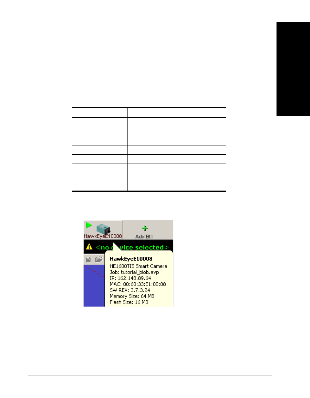
• In FrontRunner, the Smart Camera button tooltip lists the size of the RAM
and Flash for the device:
Introduction
• In the Network Viewer:
®
– Enhanced Visionscape
background color
– Enhanced Visionscape
background color
Rev. 1H, Mar 2009 Visionscape® Smart Camera HE1600T Guide 1-9
Smart Camera HE1600T 16/64 — Colorized
®
Smart Camera HE1600Te 32/128 — No
Page 22
Chapter 1 Introduction
Jobs & Storage in Non-Volatile Memory
The maximum Non-Volatile Memory area for Jobs is 16MB for the Enhanced
Visionscape
Visionscape
support files if used in the AVP:
• IntelliFi nd models
• OCV/OCR Fonts
•Perl scripts
• Acquire Tool tiff or bmp image list (when programmed to capture from disk)
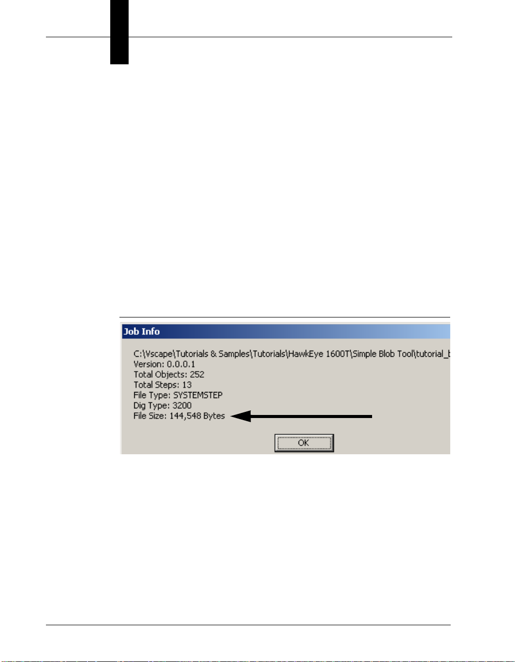
To determine the size of an AVP from FrontRunner, select File > Show Job
Info... and navigate to the AVP file on the disk. FrontRunner displays a dialog
that shows the File Size of the AVP and other statistics about the Job.
FIGURE 1–2. File Size of Job
®
Smart Camera HE1600Te (32/128), and 4.8MB for the Standard
®
Smart Camera HE1600T (16/64). This includes the Job plus any
Determine support file sizes by adding up the file sizes of the models, fonts, perl
scripts, and tiff images used in the AVP (these are usually stored under
\Vscape\Jobs Contours, Fonts subdirectories). Overall, the maximum size used
(AVP + support files) cannot exceed 16MB for the HE1600Te or 4.8MB for the
HE1600T.
1-10 Visionscape® Smart Camera HE1600T Guide Rev. 1H, Mar 2009
Page 23

2
CHAPTER 2 System Components
2
System Components
This chapter contains information about system components, and information to
help you connect the Visionscape
information describes connectors, adapters, cables, pinouts, and signals.
Note: There are no user serviceable parts inside.
®
Smart Camera HE1600T. Specific
Basic Components
Table 2–1 lists the Visionscape® Smart Camera HE1600T hardware components.
TABLE 2–1. Visionscape
Number Component Description
Cameras
GMV-0HT16-0CM0G HE1610TS
GMV-1HT16-0CM0G HE1610TH
GMV-0HF16-0CM0G HE1610TIS
GMV-1HF16-0CM0G HE1610TIH
Starter & Accessory Kits
GMV-1HF16-0SK0G HE1610TSK
Cables
®
Smart Camera HE1600T Hardware Components
Visionscape® Smart Camera VGA
Visionscape
Visionscape
Visionscape
Visionscape
®
Smart Camera XGA
®
Smart Camera VGA w/IntelliFind™
®
Smart Camera XGA w/IntelliFind™
®
Smart Camera 1610T Starter Kit
Rev. 1H, Mar 2009 Visionscape® Smart Camera HE1600T Guide 2-1
Page 24

Chapter 2 System Components
TABLE 2–1. Visionscape
®
Smart Camera HE1600T Hardware Components
(Continued)
Number Component Description
98-HT00-0CE0 HETENET-100 Cable, Ethernet M12-4 to RJ45 Ethernet Cable
Length = 10m
98-HT00-0CE2 HETENET-020 Cable, Ethernet M12-4 to RJ45 Ethernet Cable
Length = 2m
98-HT00-0CP0 HETPC-100 Cable, Power and Primary I/O M12-8 to pigtail
Length = 10m
98-HT00-0CS0 HETAC-100 Cable, Serial and Auxilary I/O M12-8 to pigtail
Length = 10m
98-HT00-0CD2 HETSC-020 Cable, Serial and M12-8 to DB9
Length = 2m
98-HT00-0CL5 HETLC-050 Cable, Light M5-4 to pigtail
Length = 5m
Adapters
98-HT00-0LM1 010-026800 Adapter, Lighting for Doal and DF-100 NER
Lights
98-HT00-0CM1 HETBMA-1 Adapter, Camera mount, Standard
98-HT00-0CM2 HETBMA-2 Adapter, Camera mount, Backward Compatible
98-0HT00-0TA0 HELTA-050 Adapter for Lens Protections Tubes (IP67)
98-0HT00-0TA1 (glass)
98-0HT00-0TA2 (no glass)
Lights
98-HT00-0LD1 010-208700 Light, DOAL 50 V2, with HE1x00T Compatible
connector
98-HT00-0LF1 010-609600 Light, DF-150, with HE1x00T Compatible
connector
98-HT00-0LR1 010-609500 Light, R-60, with HE1x00T Compatible connector
Visionscape® Smart Camera HE1600T
TCP/IP Port Connectivity
When communicating over Ethernet, the camera uses the following predefined
ports. The camera establishes connections as a Server and, therefore, listens for
Host clients to initiate the connection on a particular port. Any number of clients
2-2 Visionscape® Smart Camera HE1600T Guide Rev. 1H, Mar 2009
Page 25

Visionscape® Smart Camera HE1600T
can connect to the camera, each one with their private peer-to-peer connection
and each one monitored by a special *heartbeat* connection on port 49079 (see
Table 2–2).
TABLE 2–2. Visionscape
Port Name Protocol Number Note
File Transfer Port FTP 21 Allows the Host to send and retrieve files from the
Telnet Port Telnet 23 Console terminal to the Device, runs the vxWorks OS
DHCP Client Port DHCP 68 Supports the assignment of IP addresses from a DHCP
Web Server HTTP 80 Allow access to boot parameters when HyperTerminal
Routing Port RIP 520 Receives and updates local routing tables from the
IO Service Port TCP 49049 Controls IO on the camera, i.e., Physical and Virtual IO
Pic and Live
Acquire Port
Camera RPC Port TCP 49059 When in control, sends editing and runtime commands
Connection
Monitor Port
Reports &
Statistics Port
PartQ Retrieval
Port
TCP 49050 Takes pictures and goes to Live Video.
TCP 49079 This special connection is created automatically
TCP 49200 Used by FrontRunner and vskit programming library for
TCP 49201 Retrieves the reports records stored inline in camera
®
Smart Camera HE1600T TCP/IP Connectivity
HE1610T.
console target shell.
server for the HE1610T Smart Camera.
over Serial and Bootloader menu is not convenient.
Network.
and receives IO change notification events back to the
client.
to the camera; for example, Start, Stop, Download,
Flash, etc...
whenever any of the other connections above is made
by a client (when using the vskit libraries or by
FrontRunner). It monitors the connections and provides
a timely mechanism to report connection drops to the
client (within a few seconds).
camera reports. Reports are defined by the and can
include any results with or without images. Connections
can be programmed to be lossless, i.e., inline with the
Inspection or lossy, i.e., at a particular rate per second.
memory.
2
System Components
Rev. 1H, Mar 2009 Visionscape® Smart Camera HE1600T Guide 2-3
Page 26

Chapter 2 System Components
TABLE 2–2. Visionscape
®
Smart Camera HE1600T TCP/IP Connectivity
(Continued)
Port Name Protocol Number Note
Reports &
Statistics Control
Port
Serial TCP Ports TCP 49211
Camera
Login/Command
Port
Camera Announce
Port
TCP 49202 Allow control over a Report Connection, in particular
update rate and allows records to be added/removed
from the connection.
49212
49213
49214
UDP 49493 Gains control to the camera in order to edit and modify
UDP 49495 Broadcasts HE1600T Smart Camera identity on the
Send Formatted Output Strings serially over TCP as
programmed in the by the Formatted Output Step
its network parameters. A network login to the camera
is required to gain control with the HE1600.
current subnet used by Network View in FrontRunner,
provides general counters, camera name, IP, IP in
control, camera status, and camera software version.
Serial Port Connectivity
FrontRunner always communicates over Ethernet with the Visionscape® Smart
Camera HE1600T; however, the Serial port is fully supported by the Job in the
form of allowing Serial triggers and Serial ASCII reporting output via the
Acquire, Digital Input and Formatted Output Tools.
The serial string(s) are formatted using the *printf C syntax*. Special characters
can be used and are summarized in Table 2–3.
TABLE 2–3. Special Characters
Sequence Output Character
\a Bell (alert)
\b Backspace
\f Formfeed
\n New line
\r Carriage return
\t Horizontal tab
\v Vertical tab
\' Single quotation mark
2-4 Visionscape® Smart Camera HE1600T Guide Rev. 1H, Mar 2009
Page 27
Visionscape® Smart Camera HE1600T
TABLE 2–3. Special Characters (Continued)
Sequence Output Character
\" Double quotation mark
\\ Backslash
\ooo ASCII character in octal notation
\xhhh ASCII character in hexadecimal notation
Front Panel
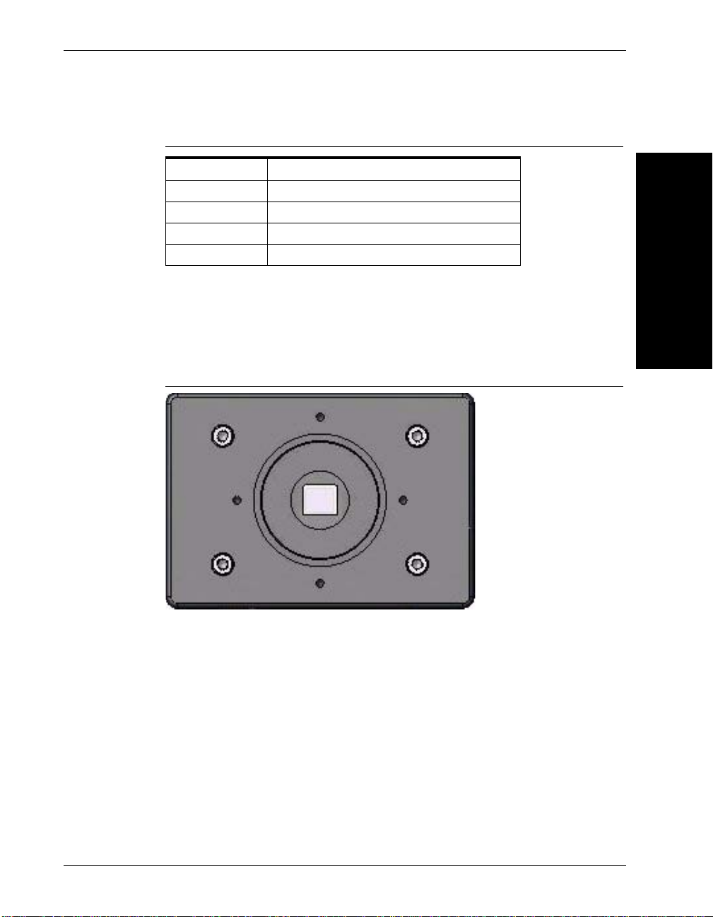
Figure 2–1 shows the front C-Mount Lens threads for the Visionscape® Smart
Camera HE1600T.
FIGURE 2–1. Front Panel
2
System Components
Rear Panel
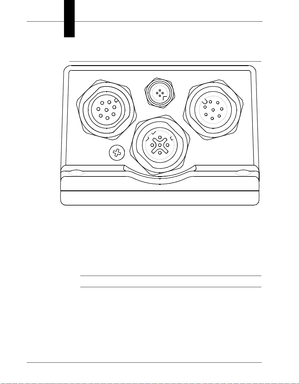
Figure 2–2 details the layout of the rear panel.
Rev. 1H, Mar 2009 Visionscape® Smart Camera HE1600T Guide 2-5
Page 28
Chapter 2 System Components
X1 X2
X3
S1
X4
FIGURE 2–2. Rear Panel Layout
• X1 — Power & Primary I/O (M12 A-coded, plug)
• X2 — External Light Power, Strobe only (M5, socket)
• X3 — Secondary I/O, Serial (M12 A-coded, socket)
• X4 — Industrial Ethernet (M12 D-Coded)
• S1 — QuicSet™ (Remove screw for access)
Note: On earlier productions units only. Function not required.
Mode/Status LEDs
Figure 2–3 shows the mode and status LEDs.
2-6 Visionscape® Smart Camera HE1600T Guide Rev. 1H, Mar 2009
Page 29
Visionscape® Smart Camera HE1600T
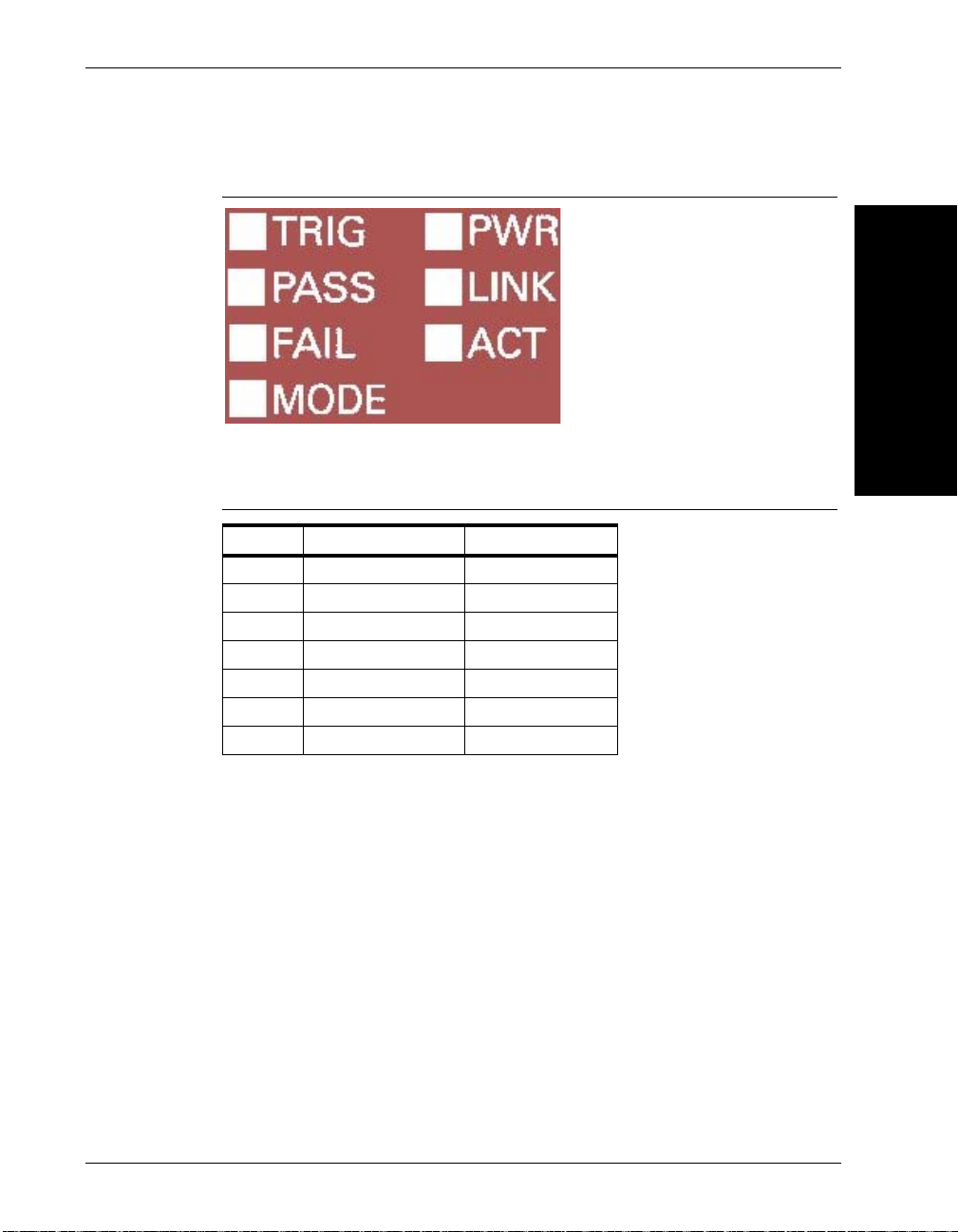
FIGURE 2–3. Mode/Status LEDs
Table 2–4 describes the mode and status LEDs.
TABLE 2–4. Mode/Status LEDs
Name Description LED Color
TRIG Trigger LED Yellow
PASS Pass LED Green
FAIL Fail LED Red
MODE Mode LED Yellow
PWR Power on LED Green
LINK Ethernet Link Green
ACT Ethernet ACT Yellow
2
System Components
These LEDs convey visually power-on status and error codes.
Important Label Information
Each Visionscape® Smart Camera HE1600T has its own label, which contains
important information about that Smart Camera.
• MODEL NUMBER/CATALOG NUMBER — The model number for your
Visionscape
• PN — The part number of your Visionscape
• SN — The serial number of your Visionscape
• MAC ADDRESS — This unique address is important because, by default, a
Visionscape
Rev. 1H, Mar 2009 Visionscape® Smart Camera HE1600T Guide 2-7
®
Smart Camera HE1600T.
®
Smart Camera HE1600T
®
Smart Camera HE1600T.
®
Smart Camera’s name on the network is
Page 30

Chapter 2 System Components
“HawkEyeXXXXXX,” where XXXXXX is the last six alphanumeric
characters in its MAC address. So, for the Visionscape
HE1600T with MAC address 00:60:33:E1:FF:FA, the default network name
is “HawkEyeE1FFFA”.
• Optional IntelliFind License Key (applies to HE1610TIS & HE1610TIH
only)
Power-on Sequence
Each stage of the power-on sequence drives the LEDs in a binary up-count
fashion according to Table 2–5. The LEDs illuminate before the test is executed
and remain in that pattern until the next test is run or an error condition is
detected and displayed.
Error Codes
In the event of an error being detected, the beeper beeps five times and an error
code (in binary form) representing the test that failed flashes on the LEDs. The
LEDs continue to flash until the <Escape> character is sent on the serial port, at
which point an error message is logged to the serial port and the Diagnostic
Monitor is launched. The serial port terminal server must be set to the following
parameters: 115200, 8, N, 1.
Table 2–5 describes the Mode/Status LED power-on sequence and error codes.
®
Smart Camera
TABLE 2–5. Mode/Status LED Power-On Sequence & Error Codes
Mode Fail Pass Trig Test Performed
• Data Line Test
• Address Line Test
• • Bootloader CRC Check
• Kernel CRC Check
• • RS-232 Internal Loopback
• • FPGA Load Test
• • • FPGA PCI Config Test
2-8 Visionscape® Smart Camera HE1600T Guide Rev. 1H, Mar 2009
Page 31

Visionscape® Smart Camera HE1600T
TABLE 2–5. Mode/Status LED Power-On Sequence & Error Codes
Mode Fail Pass Trig Test Performed
• FPGA Video Buffer Test
• • FPGA DMA Transfer Test
• • FPGA Expose Done Interrupt Test
• • • FPGA Read Done Interrupt Test
Beeper
The Visionscape® Smart Camera’s beeper is user configurable and indicates
Pass/Fail conditions.
Mounting & Wiring the Visionscape® Smart Camera HE1600T
• Mount the camera securely in its camera stand (not supplied).
• Make sure the camera is mounted at the correct distance for the optics
you’ve purchased.
• Connect the Ethernet cable (X4) and the power cable (X1) to the
Visionscape
Connect the Visionscape
®
Smart Camera HE1600T (see “Rear Panel” on page 2-5).
®
Smart Camera HE1600T to a 24V power supply.
2
System Components
Mounting Using Front Block
Note: Do not insulate the mounting block. The mounting block of the
Visionscape
metal-to-metal contact is required for effective cooling. Refer to Appendix C,
“Specifications,” for mounting block dimensions.
You can mount the Visionscape
located on the top, bottom, and each side of the front block, as shown in
Figure 2–4.
Rev. 1H, Mar 2009 Visionscape® Smart Camera HE1600T Guide 2-9
®
Smart Camera HE1600T is part of the heat dissipation system, and
®
Smart Camera HE1600T using the M4 holes
Page 32

Chapter 2 System Components
M4 x .7 x 10
Part Number - 98-HT00-0CM1
FIGURE 2–4. Locations for Mounting Using Front Block
Caution: Using screws that are too long for the threaded holes may damage
®
the Visionscape
Smart Camera HE1600T. The accessory mounting blocks
use 10mm machine screws.
Mounting Using Standard Mounting Block
You can mount the Visionscape® Smart Camera HE1600T using the standard
mounting bloc (see Figure 2–6).
FIGURE 2–5. Standard Mounting Block
2-10 Visionscape® Smart Camera HE1600T Guide Rev. 1H, Mar 2009
Page 33

Visionscape® Smart Camera HE1600T
Part Number - 98-HT00-0CM2
M3 x .5 x 6 ScrewM4 x .7 x 10 Screws
Mounting Using Accessory Mounting Block
You can mount the Visionscape® Smart Camera HE1600T using the accessory
mounting block (see Figure 2–6). The backward compatible mounting block
positions a Visionscape
Visionscape
FIGURE 2–6. Accessory Mounting Blocks
®
Smart Camera HE1600 for optical alignment.
®
Smart Camera HE1600T in the same position as a
2
System Components
Location for Backward Compatible Mounting Block
Figure 2–7 shows the screw hole locations for the backward compatible
mounting block.
FIGURE 2–7. Location for Backward Compatible Mounting Block
Rev. 1H, Mar 2009 Visionscape® Smart Camera HE1600T Guide 2-11
Page 34

Chapter 2 System Components
IN A (or IN B)
15-30V
Signal
Signal
15-30V
Camera
PNP Source
Camera
NPN Sink
IN B (or IN A)
IN A (or IN B)
IN B (or IN A)
GPIO OUT COM
See Note 1
GPIO IN COM
GPIO x
15-30V
Signal
See Note 2
GPIO IN COM
GPIO x
Signal
15-30V
GPIO OUT COM
Camera
PNP Source
Camera
NPN Sink
Caution: Using longer screws may damage the Visionscape® Smart Camera
HE1600T.
Field I/O Wiring Examples
Input Opto Wiring
Figure 2–8 shows the input opto wiring for isolated NPN and PNP sources.
FIGURE 2–8. Trigger Input Opto Wiring (NPN and PNP)
Figure 2–9 shows the input opto wiring fo r non-isolated NPN and PNP sources.
FIGURE 2–9. GPIO Input Opto Wiring (NPN and PNP)
2-12 Visionscape® Smart Camera HE1600T Guide Rev. 1H, Mar 2009
Note 1: GPIO OUT COM typically connected to ground.
Note 2: GPIO OUT COM typically connected to Voltage.
Page 35

Output Opto Wiring
NPN Sink
Signal
See Note 1
GPIO IN COM
GPIO x
GPIO OUT COM
GPIO OUT COM
GPIO x
See Note 2
GPIO IN COM
15-30V
PNP Source
15-30V
Signal
CameraCamera
OUT COM
OUT x
15-30V
OUT COM
OUT x
GND
Input
PLC
15-30V
PLC
Relay
Camera Camera
Figure 2–10 shows the output opto wiring for isolated input.
FIGURE 2–10. GPIO Output Opto Wiring (NPN and PNP)
Note 1: GPIO IN COM typically connected to ground.
Note 2: GPIO IN COM typically connected to Voltage.
Figure 2–11 shows the output opto wiring for isolated relay and PLC inputs.
FIGURE 2–11. Output Opto Wiring (Relay and PLC Inputs)
Field I/O Wiring Examples
2
System Components
Figure 2–12 shows the output opto wiring for non-isolated inputs.
Rev. 1H, Mar 2009 Visionscape® Smart Camera HE1600T Guide 2-13
Page 36

Chapter 2 System Components
See Note
GPIO OUT COM
GPIO x
GPIO IN COM
15-30V
GPIO IN COM
See Note
GPIO x
GPIO OUT COM
15-30V
PLC
Input
GND
FIGURE 2–12. GPIO Output Opto Wiring (Relay and PLC Inputs)
1. GPIO IN COM typically connected to ground.
Caution: The maximum current that can pass through the optoisolators is
50 mA. Non-isolation setup can cause damage to the Visionscape
®
Smart
Camera HE1600T if excessive voltage is applied to the optoisolators.
2-14 Visionscape® Smart Camera HE1600T Guide Rev. 1H, Mar 2009
Page 37

Field I/O Wiring Examples
IN A
IN B
OUT 1
OUT COM
GP IO IN C OM
opto input
Rin
Ron
opto o u tp u t
OUT 2
Ron
OUT 3
Ron
GPIO 1
Ron
opto outp ut
GPIO OUT COM
Rin
GPIO 2
Ron
Rin
GPIO 3
Ron
Rin
GPIO 4
Ron
Rin
opto inp u t
Ron=24 ohm typ.
35 ohm max.
Rin=18 Kohm±5%
FIGURE 2–13. Visionscape
®
Smart Camera I/O Simplified Circuit Diagram
2
System Components
Rev. 1H, Mar 2009 Visionscape® Smart Camera HE1600T Guide 2-15
Page 38

Chapter 2 System Components
External Strobe & Sensor
For continuous motion or high-speed indexing applications, an external st robe
and sensor may be required to freeze each part before the image can be acquired.
When choosing your part sensor, you must consider the time interval between the
part passing into the sensing zone and an electrical signal being generated. When
there is a large variation in process speed, considerable variation in location of
the part within the Field of View (FOV) may result. The FOV specified for the
Visionscape
variation in location.
®
Smart Camera HE1600T should be large enough to cover the
Power Requirements
Refer to Table 2–6 when determining the power supply requirements for your
Smart Camera Vision System.
TABLE 2–6. Smart Camera Vision System Power Requirements
Component 24VDC
Visionscape® Smart Camera HE1610T 24 volts @ 350ma typical
Power Supply Wiring
For complete information about the power supply wiring, see “Power & Primary
I/O Connector” on page A-1, and “HETPC-100 - Power & Primary I/O Cable”
on page B-1.
2-16 Visionscape® Smart Camera HE1600T Guide Rev. 1H, Mar 2009
Page 39

3
CHAPTER 3 Ethernet/IP Communications
This chapter contains information about Visionscape® Smart Camera HE1600T
support for Ethernet/IP (EIP) communications.
Ethernet/IP is an industrial protocol that provides out of the box connectivity to
Allen-Bradley PLCs for the HE1610T Smart Camera. Ethernet/IP provides two
mechanisms for exchanging data between a PLC and a device:
• Implicit Messaging (also called I/O) — Implicit messages are messages set
up automatically by the PLC on connection to the device to refresh data at
given intervals. Conceptually, a block of data (memory) is shared between
the PLC and the device. This block contains binary data made up of simple
scalar types: integers, floats and strings. This block of data is kept in sync on
the PLC and on the device typically every 10 msec. Both the PLC and the
device can write and read data from this block. This is implemented in
V3.7.3.
• Explicit Messaging — Expli cit messages are messages you set up in your
PLC program to retrieve data at specific points in time. This is different from
the implicit mechanism which exchanges a block of data at regular intervals
as soon as a connection to the device is made, without the need to write any
special instructions in the PLC program. This is not supported by V3.7.3.
3
Ethernet/IP
Communications
Note: Messaging is only operational in online mode when a job is running on the
SmartCamera. Only I/O Points will function when running in Setup Mode on the
PC.
Rev. 1H, Mar 2009 Visionscape® Smart Camera HE1600T Guide 3-1
Page 40

Chapter 3 Ethernet/IP Communications
A/B Logix PLCs That Support Ethernet/IP I/O Messaging
With this release only Allen-Bradley PLCs that are Ethernet/IP ready (i.e., Logix
series PLCs) are supported using implicit messaging. Table 3–1 details the
Controllers with required Interface modules that support Ethernet/IP Implicit
(i.e., I/O) messaging.
TABLE 3–1. Allen-Bradley PLCs That Are Ethernet/IP Ready
Cat. No.
1769
CompactLogix
1768
CompactLogix
FlexLogix 512 Kbytes 512 digital
ControlLogix 8 Mbytes 128,000
SoftLogix5800 PC dependent PC
Memory
(max) I/O (max) Local I/O
1.5 Mbytes 30 Compact
3 Mbytes 30 Compact
I/O modules
I/O modules
128 analog
digital
3,800 analog
dependent
Two blocks are defined that allow the manipulation of IO points, camera control
and status bits and user-defined data by both the PLC and the HE1610T device.
These two blocks are identical except for the size of the user-defined data, which
is either 64 bytes or 400 bytes.
Programming
Software
1769
Compact I/O
1769
Compact I/O
1794 FLEX
I/O
1797 FLEX
Ex I/O
1756
ControlLogix
I/O
none RSLogix 5000
RSLogix 5000 • relay ladder
RSLogix 5000 • relay ladder
RSLogix 5000 • relay ladder
RSLogix 5000 • relay ladder
C/C++
routines
Programming
Languages
• function block diagram
(FBD)
• structured text (ST)
• sequential function
chart (SFC)
• function block diagram
(FBD)
• structured text (ST)
• sequential function
chart (SFC)
• function block diagram
(FBD)
• structured text (ST)
• sequential function
chart (SFC)
• function block diagram
(FBD)
• sequential function
chart (SFC)
• relay ladder
• function block diagram
(FBD)
• structured text (ST)
• sequential function
chart (SFC)
Ethernet/IP
Interface
• 1769-L32E
(embedded)
• 1769-L35E
(embedded)
• 1768-ENBT
• 1788-ENBT
• 1756-EN2T
• 1756-EN2F
• 1756-ENBT
• PC Ethernet card
The PLC manipulates the data within the block through what is called
assemblies. There are two assemblies defined, one for OUTPUT (writing to the
Binary Block of data) and one for INPUT (reading from the Binary Block of
data) as seen by the PLC. For Visionscape, the OUTPUT assembly is used to
receive/read data from the PLC and the INPUT assembly is used to send/write
data to the PLC.
3-2 Visionscape® Smart Camera HE1600T Guide Rev. 1H, Mar 2009
Page 41

Note: The PLC programmer needs to select the appropriate assembly/assemblies
to manipulate the block of data within the PLC program. In this release, the block
of data is made up of a fixed section containing 32 bit of IO points and a userdefined section.
In Visionscape
appropriate assembly is selected automatically, these mechanisms are standard
virtual IO for the fixed IO section of the block and Perl scripts for the userdefined section. The fixed IO section is dynamic, i.e., changes to IO points in the
block are sent to/received from the PLC on the next implicit scan. Changes to the
user section of the block are latched by the Inspection at the start of the vision
cycle and sent back to the PLC at the end of the vision cycle.
Ethernet/IP IO Points
Ethernet/IP IO Points
®
, the data is accessed by standard mechanisms and the
3
Ethernet/IP IO Points can be read and written by their corresponding virtual IO
points with the existing tool set including DigitalInput and DigitalOutput steps.
The state of the IO points is updated each time the camera receives an Output
Assembly; the values are latched when the DigitalInput step is executed.
Changes to the IO Points from a DigitalOutput step or other output IOPointDm
are written immediately to the Input Assembly. The values will be received by
the PLC on the next implicit Input Assembly transfer.
Note: Resolution of the I/O is dependent on the PLC’s Ethernet/IP Requested
Packet Interval (RPI) setting. I/O transitions shorter than the duration of the RPI
will not be visible to the PLC. Please refer to Rockwell documentation for further
information regarding this setting. To resolve I/O from a device of width x msec,
the RPI setting of the Ethernet module must be programmed to x/2 msec or
lower. For example, to detect pulses generated by the d evice in the PLC pr ogra m
of width 10 msec, set the RPI to 5 msec or less.
Binary Data Block
The Inspection Step contains a BinaryBlockDm named “EIP Data”. This datum
contains a copy of the Input Assembly and Output Assembly data blocks. The
contents are copied from the system Output Assembly at the start of processing
of an inspection to the Inspection’s latched copy of the Output Assembly. This is
Ethernet/IP
Communications
Rev. 1H, Mar 2009 Visionscape® Smart Camera HE1600T Guide 3-3
Page 42

Chapter 3 Ethernet/IP Communications
Output
Assy
Input
Assy
PLC
Ethernet/IP
Imp l ici t
O utput
Assy
Vision
System
Inp ut
Assy
OA
Insp 1
EIP Data
IA
Insp 2
EIP Data
OA
IA
E the rnet/IP
Imp lic it
On Trigger
End of
Inspe c tio n Cyc le
at the time of the trigger for triggered inspections or the start of an inspection
cycle for non-triggered inspections.
The Inspection’s instance of the Input Assembly is written back to the system’s
Input Assembly at the end of an inspection cycle. This is at the time when Data
Valid is asserted at the end of the vision cycle. Only the bytes written by the
inspection are changed in the system’s Input Assembly . If no bytes are written by
an inspection, the system Input Assembly will be unchanged. This allows
multiple asynchronous inspections to write to separate sub-blocks within the user
data block and not interfere with each other. The UserID tag register always
reflects the last inspection cycle that has completed.
INPUT Assembly (Instance 100) (80 bytes) OUTPUT Assembly (Instance 112) (80 bytes)
DINT Meaning DINT Meaning
0 32 Bits of Camera Virtual IO 0 32 Bits of Camera Virtual IO
The contents of the User Data Block are read and written by inserting Custom
Steps. Two Perl scripts (BinaryBlockRead & BinaryBlockWrite) are provided to
access the latched Inspection OUTPUT assembly and INPUT assembly data,
respectively. The assembly objects are described in the following two tables:
3-4 Visionscape® Smart Camera HE1600T Guide Rev. 1H, Mar 2009
Page 43

Binary Data Block
INPUT Assembly (Instance 100) (80 bytes) OUTPUT Assembly (Instance 112) (80 bytes)
DINT Meaning DINT Meaning
1 User-defined tag value 1 User-defined tag value
2 Camera Status Register 2 Camera Control Register
3 Last Error 3 Reserved
4...19 64 bytes of user data 4...19 64 bytes of user data
INPUT Assembly (Instance 101) (416 bytes) OUTPUT Assembly (Instance 113) (416 bytes)
DINT Meaning DINT Meaning
0 32 Bits of Camera Virtual IO 0 32 Bits of Camera Virtual IO
1 User-defined tag value 1 User-defined tag value
2 Camera Status Register 2 Camera Control Register
3 Last Error 3 Reserved
4...103 400 bytes of user data 4...103 400 bytes of user data
The definitions of the fields are listed below.
3
Ethernet/IP
Communications
DINT 0: 32 Bits of Camera Virtual IO
This 32 bit value maps to a subset of virtual IO points on the camera (VIO 129
through VIO 160).
For the INPUT assembly, the value of this register always reflects the state of the
corresponding IO points from the camera. By using the corresponding virtual IO
point on the camera, these IO points can reflect the state of any IOOutputDm
such as picture done, or set by a user expression using a DigitalOutput step.
For the OUTPUT assembly, the value of this register is written to the
corresponding IO points of the camera. They can be used by any IO input datum,
such as triggers, or read by using a DigitalInput step.
DINT 1: User-defined Tag Value
The user-defined tag value is a single DINT that is sent to the camera through
implicit messaging to Assembly Instance 2. When the camera receives a new
user tag from Assembly Instance 112 (or 113), it is latched in the inspection’s
copy of the Assembly and will be reflected through Assembly Instance 100 (or
101) at the end of the inspection cycle. This allows the PLC to match inspection
Rev. 1H, Mar 2009 Visionscape® Smart Camera HE1600T Guide 3-5
Page 44

Chapter 3 Ethernet/IP Communications
results in the Input Assembly to the Output Assembly that was latched at the start
of the same inspection cycle.
DINT 2: Camera Control Register
TABLE 3–2. Control Register Bit Definitions
BIT Meaning
0 Stop, transition 0->1 to stop inspections
1 Start, transition 0->1 to start inspections
2 Clear error, transition 0->1 to clear Last Error
3 Clear command status, transition 0->1 to clear command stat
4…31 Reserved
DINT 2: Camera Status Register
TABLE 3–3. Status Register Bit Definitions
BIT Meaning
0 System Online
1 = System is online and a job is loaded on the camera
0 = Camera is not ready for inspection to go online; it is either
loading a job or no job is loaded on the system.
1 Inspection Online
1 = Inspection is online, the job is running on the camera
0 = Inspection is offline
2 Command Complete. Cleared by issuing ‘Clear Command Status’
1 = Last issued command has completed
0 = Last issued command is being processed
3 Command Succeeded. Updated whe n command is completed.
Cleared by issuing ‘Clear Command Status’
1 = Success
0 = Failure, check Last Error for more information
4…31 Reserved
Commands sent to the Control Register are ignored when the camera is offline;
the camera must be online before sending a Start trigger.
3-6 Visionscape® Smart Camera HE1600T Guide Rev. 1H, Mar 2009
Page 45

Binary Data Block
DINT 3: Last Error
Last Error returns the last error code sent to the Ethernet/IP subsystem. It will
return all zeros if no error occurred. The last error code can be reset to zero by
transitioning the Clear Last Error bit of the control register from zero to one.
Error bits are allocated below:
Bit
Mnemonic
EIP_ERROR_TRUNCATED 0x0001 Set when the writes data in bytes 64 -
DINT 4…19/4…103: User Data
This contains 64 (or 400 bytes) of user-defined data. The content of the data
block is defined by how the bytes are written by the vision job using Perl tools.
The data is unstructured within the Ethernet/IP transport; it is up to the PLC and
Vision programmer to ensure the data structures match on each end of the
transport.
Mask Description
399 of the user data section, and the Ethernet/IP
requests the small assembly.
3
Ethernet/IP
Communications
The user-defined data is progr a mmed in the by using two Perl scripts described
in the next section. Data allocated in the user-defined block must match
equivalent PLC data types. The mapping between Data types in the to PLC types
is summarized below:
Datum Type BinaryBlockIO Type PLC Native Type
StatusDm BOOL DINT 4
IntDm INTEGER DINT 4
DoubleDm FLOAT REAL 4
StringDm STRING STRING
(DINT + STRLEN)
PointDm POINT REAL x 2 8
LineDm LINE REAL x 3 12
DistanceDm DIST REAL 4
AreaDm A REA REAL 4
AngleDm ANGLE REAL 4
Rev. 1H, Mar 2009 Visionscape® Smart Camera HE1600T Guide 3-7
1
Byte Count
4 + STRLEN
Page 46

Chapter 3 Ethernet/IP Communications
BinaryBlockRead Perl Tool UI BinaryBlockWrite Perl Tool UI
1
All data in the user-defined binary block is aligned on 4-byte boundary to match
the tanglement rules expected by the PLC. Padding bytes are added (for
STRING) as necessary so the next type following a STRING is 4 bytes aligned.
User Data Block Accessor Perl Tools
T wo Perl scripts (BinaryBlockRead & Bi naryBlockWrite) are provided to access
the latched Inspection OUTPUT assembly and INPUT assembly data,
respectively.
• The BinaryBlockRead Perl script mu st be inserted in the after the AcqStep
has executed and before any other tool that uses the data in the binaryblock.
Typically, this will be as the first tool inside the Snapshot.
• The BinaryBlockWrite Perl script must be inserted in the after any other tool
that calculates results to be stored in the binaryblock. Typically, this will be
as the last tool in the Inspection.
BinaryBlockRead/Write Perl Scripts
Both Script tools share a similar UI interface. Additional features are available
for the BinaryBlockWrite script to control when Data is sent to the Network.
The base user interface lets the user build the mapping between the binary data in
the Ethernet/IP block to a set of Datums in the .
• First Datum/Byte Block Offset — Offset in bytes from the beginning of the
user block where the data is read from/written to. This value is aligned on a 4
3-8 Visionscape® Smart Camera HE1600T Guide Rev. 1H, Mar 2009
Page 47

Binary Data Block
byte boundary by the tool with respect to the beginning of the user-defined
binary block.
• Add Datum Type — List of Datum types for mapping bytes in the binary
block to Datums and vice-versa as shown below:
3
Ethernet/IP
Communications
Rev. 1H, Mar 2009 Visionscape® Smart Camera HE1600T Guide 3-9
Page 48

Chapter 3 Ethernet/IP Communications
– Perl Tool - BinaryBlockRead - Add Datum Type:
• BOOL (4 bytes) — Can be connected to a StatusDm (Checkbox).
Note: The boolean value should be read from bit 0 of the DWORD on
the PLC. The state of the remaining bits 1 through 31 is not guaranteed.
• INTEGER (4 bytes) — Can be connected to an IntDm
(Thresholds, etc…).
• FLOAT (4 bytes) — Can be connected to a DoubleDm
(Tolerances, etc…).
• STRING (4 + LEN Bytes) — Can be connected to a StringDm
(Match String, etc…). When adding a String, its maximum
expected length must also be specified to properly reserve a fixed
number of bytes in the block. A 4 byte Length field (at the
beginning of the STRING) is allocated automatically in the block
also.
3-10 Visionscape® Smart Camera HE1600T Guide Rev. 1H, Mar 2009
Page 49

Binary Data Block
– Perl Tool - BinaryBlockWrite - Add Datum Type:
• BOOL (4 bytes) — Can be connected to a StatusDm (Pass/Fail).
• INTEGER (4 bytes) — Can be connected to an IntDm
(Counters, etc…).
• FLOAT (4 bytes) — Can be connected to a DoubleDm
(Score, etc…).
3
Ethernet/IP
Communications
• STRING (LEN bytes + 4) — Can be connected to a StringDm
(DMR Text, etc…). When adding a String, its maximum expected
length must also be specified to properly reserve a fixed number of
bytes in the block. A 4 byte Length field (at the beginning of the
STRING) is allocated automatically in the block also.
• POINT (3 Floats) — Can be conn ected to a Po intDm
(Location, etc…).
• LINE (3 Floats) — Can be connected to a LineDm
(FastEdge, etc…).
• DIST (1 Float) — Can be connected to a DistanceDm
(Pt2Pt Distance, etc…).
• AREA (1 Float) — Can be connected to an AreaDm
(Blob Area, etc…).
• ANGLE (1 Float) — Can be connected to an AngleDm
(Line Angle, etc…).
Rev. 1H, Mar 2009 Visionscape® Smart Camera HE1600T Guide 3-11
Page 50

Chapter 3 Ethernet/IP Communications
The Example String of length 12 shown below actually uses 16 bytes in the
block:
• Add Datum Reference At End — Adds a Datum Reference of type “Add
Datum Type” at the end of the datum list. The reference can then be
connected to point to a particular Datum in the . For Read operation, Datum
must be connected to a tool that runs after the BinaryBlockRead tool. For
Write operation, Datum must be connected to a tool than runs before the
BinaryBlockWrite tool.
• Edit Datum Reference — Edits the Datum Reference at the given index
(specified by the Datum Reference to Edit/Remove property) and changes its
type to the current “Add Datum Type” selection. Note that, if the previous
reference was connected to a Datum in the , this reference will be reset by
this operation. The index must be a number between 1 and N where N is the
number of Datum references in the block. For example, for EIPRead
example above: to edit/remove “0: Datum 1 (STRING)”, enter 1 in that field.
• Remove Datum Reference — Removes the Datum Reference at the given
index (specified by the Datum Reference to Edit/Remove property).
3-12 Visionscape® Smart Camera HE1600T Guide Rev. 1H, Mar 2009
Page 51

Binary Data Block
• Datum Reference to Edit/Remove — Specify the Datum reference by index
that is selected for Editing or Removal (as described in the previous two
bullets).
• Delete Data Reflist — Deletes the entire bl ock datu m reference list, i.e.
deletes the mapping from Binary Block to Datums (BinaryBLockRead) or
the mapping from Datums to Binary Block (BinaryBlockWrite), hence
allowing the mapping to be reconstructed.
• Send Data Block (Write Script only) — Allow the BinaryBlock to be sent to
the Network either at the end of the current Inspection cycle or immediately.
• Include User Tag First (Write Script only) — When checked, the first 4 bytes
of the User Data block will be a copy of the User Tag that was sent by the
PLC for this Inspection cycle.
3
Ethernet/IP
Communications
Rev. 1H, Mar 2009 Visionscape® Smart Camera HE1600T Guide 3-13
Page 52

Chapter 3 Ethernet/IP Communications
Example Ethernet/IP Read/Write Test
This reads the match string from the Network through Ethernet/IP at the
beginning of each cycle and sets it in a Data Matrix tool. The decode string,
position and status of the Data Matrix tool are sent at the end of each cycle to the
Network through Ethernet/IP as results.
FIGURE 3–1. Ethernet/IP Read/Write Test
3-14 Visionscape® Smart Camera HE1600T Guide Rev. 1H, Mar 2009
Page 53

4
CHAPTER 4 Visualization HMIs
This chapter contains information about Visionscape® Smart Camera HE1600T
support for Visualization HMIs.
The HE1600T features a built in runtime monitoring web page that can be
viewed from any supported browser on the same network. Supported browsers
include:
• Internet Ex plorer 5.0 or later
• Firefox 3.0 or later
The Runtime Page shows an image from the Visionscape
HE1600T, along with inspection counters and buttons to control certain aspects
of the display. A title bar displays the camera name, IP address and the name of
the Job. Options are available to change if and where the counters, buttons, and
titlebar are displayed. Additionally, up to 10 values from the job can be displayed
along with each image. These values can either be overlayed over the image, or
shown as a tabular report underneath the image.
Note: The HMI web page will not automatically detect if the Vision Job it is
connected to has been changed or edited. Therefore, in this instance, please
refresh the page manually (via the web browser refresh button).
You can set all settings and options through a series of option pages that can
appear over the main display. All parameters are saved as cookies in the web
browser environment so that, the next time the Runtime Page is loaded for that
device, the layout and settings are retained.
®
Smart Camera
4
Visualization HMIs
Rev. 1H, Mar 2009 Visionscape® Smart Camera HE1600T Guide 4-1
Page 54

Chapter 4 Visualization HMIs
The default behavior is:
• Images and counters are fo r the first inspection in the job
• All images (pass & fail) are shown
• The display is refreshed automatically at regular intervals (auto=on)
• Graphics are overlaid on the image
Note: For performance reasons, not all graphics are available when viewing
images on the web page. Only vector graphics are displayed.
• The border around the image signifies the status of the inspection
(green=pass, red=fail)
The Runtime Image Page is accessed through a URL that contains the IP address
of the camera, and optional parameters. The default page is accessed by
specifying the IP address of the camera in a web browser. For example:
http:// 161.218.121.58
(example only; use actual IP address of the HE1600T)
If no previous settings have been set by the user, the display will be similar to the
screen in Figure 4–1
4-2 Visionscape® Smart Camera HE1600T Guide Rev. 1H, Mar 2009
Page 55

FIGURE 4–1. Main HMI Window
The web page includes the following elements:
4
• Title Bar — Displays the name and IP address of the camera, and the name
of the job (AVP). Note that the file extension (.avp) is removed from the
displayed file name.
• Failures Button — When this button is selected, only images related to failed
inspections are displayed.
• Auto Button — When this button is selected, the image and counters are
updated automatically. If the button is not selected, both the image and
counters are frozen.
• Refresh Button — Selecting thi s button manually updates the image and
counters.
Note: If the Refresh Button is selected while the system is in AutoRefresh Mode, the image disappears and stats freeze for a period of
approximately 10 seconds after which point the system returns to
normal operation.
Rev. 1H, Mar 2009 Visionscape® Smart Camera HE1600T Guide 4-3
Visualization HMIs
Page 56

Chapter 4 Visualization HMIs
• Status — The run status of the inspection (RUNNIN G or STOPPED).
• Counters — Displays the Total, Pass, Fail and Alarm counters for the
selected inspection.
4-4 Visionscape® Smart Camera HE1600T Guide Rev. 1H, Mar 2009
Page 57

Settings Pages
You can configure all the options and settings using the settings pages. By
default, the Settings button is not displayed; to display the Settings button, see
Figure 4–8, “Buttons,” on page 4-9.
To display the settings pages, specify the URL with the “setopt=1” parameter:
http://ip_address/?setopt=1
This will display the Runtime Page overlayed with the Options Setup page:
FIGURE 4–2. Options Setup Page
Settings Pages
4
Use the tabs at the top of the screen to navigate between the several setup pages.
To close the setup screens and return to the main display, use the Close button
(“X”) at the upper right corner.
The Layout page controls many layout features, which are organized into groups.
Rev. 1H, Mar 2009 Visionscape® Smart Camera HE1600T Guide 4-5
Visualization HMIs
Page 58

Chapter 4 Visualization HMIs
Layout Options
You can configure the overall layout of the Runtime Page via the Settings pages.
Figure 4–3 shows a default configuration:
FIGURE 4–3. Default Configuration
Buttons, status, and counters appear to the right of the image area. The buttons
are sized for use via a touch screen.
Figure 4–4 displays how the layout has been changed to position the counters at
the top, shown without titles to save room. Additionally, an Options button now
appears in the right side area.
4-6 Visionscape® Smart Camera HE1600T Guide Rev. 1H, Mar 2009
Page 59

Settings Pages
FIGURE 4–4. Buttons at Right & Counters & Status Above Image
Another example with buttons and counters at the top:
FIGURE 4–5. Status, Counters, & Buttons Displayed Above Image
It is also possible to hide all elements except the image.
4
Rev. 1H, Mar 2009 Visionscape® Smart Camera HE1600T Guide 4-7
Visualization HMIs
Page 60

Chapter 4 Visualization HMIs
Modes
Selecting the Modes group results in the following options being displayed:
FIGURE 4–6. Modes
• Launch in Auto Mode — Determines whether or not the Runtime Page
defaults to be in auto-refresh mode when launched. The default is On.
• Launch in Failures Mode — Determ ines whether or not the Runtime Page
defaults to be in show failures mode when launched. The default is Off.
4-8 Visionscape® Smart Camera HE1600T Guide Rev. 1H, Mar 2009
Page 61

Image Display
FIGURE 4–7. Image Display
Settings Pages
4
• Fit Image Height/Fit Image Width — These two settings determine how the
image is scaled to fit the display area. If both are off, then no scaling is
performed and the image is displayed 1:1. If both are on, then auto scaling is
performed, fitting the width or height depending on which fits the display
area better. Otherwise, the image is scaled either to fit the width or height.
The default is Auto (both On).
• Show Pass/Fail Border — Displays a border around the image. Green = pass,
red = fail. The default is On.
• Show Tool Graphics — Shows tool graphics overlayed on the image. Not all
tool graphics are supported. The default is On.
• Warp Image to Fit Display — Scaling the image to fill the display area can
have an adverse effect on the quality of the graphics displayed. As an
example, lines can be missing. This setting improves the quality of the
displayed graphics. Turning this off will reduce the overhead on the 1600T.
The default is On.
Rev. 1H, Mar 2009 Visionscape® Smart Camera HE1600T Guide 4-9
Visualization HMIs
Page 62

Chapter 4 Visualization HMIs
Buttons
FIGURE 4–8. Buttons
• Show Auto Button — If on (default), the Auto button is shown.
• Show Buttons in Minibar — If on, the buttons are shown in the Minibar area,
which appears under the titlebar. If off (default), the buttons will be shown to
the right of the image area.
• Show Failures Button — If on (default), the Failures button is displayed.
• Show Graphics Button — If on, the Graphics button is shown. This button
controls if the graphics are overlayed on the image. The default is Off.
• Show Refresh Button — If on (default), the Refresh button is displayed.
• Show Settings Butt on — If on, the Set tings button is displayed.
4-10 Visionscape® Smart Camera HE1600T Guide Rev. 1H, Mar 2009
Page 63

Counters & Status
FIGURE 4–9. Counters & Status
• Show Alarms Counter — If on (default), the alarms counter is shown.
Settings Pages
4
• Show Counters in Minibar — If on, the count ers are shown in the Minibar
area, which appears under the titlebar. If off (default), the counters will be
shown to the right of the image area.
• Show Counter Titles — If on (default), a title is displayed to the left of each
counter.
• Show Device Status — If on (default), the device status (RUNNING,
STOPPED) is displayed.
• Show Failures Counter — If on (default), the failures cou nter is shown.
• Show MemAvail and MemFrags Counters — If on, two counters are shown
which display memory use status for the HE1600T. The default is Off.
• Show Passed Counter — If on (default), the passed counter is displayed.
• Show Total Counter — If on (default), the total counter is shown.
Rev. 1H, Mar 2009 Visionscape® Smart Camera HE1600T Guide 4-11
Visualization HMIs
Page 64

Chapter 4 Visualization HMIs
Extras
FIGURE 4–10. Extras
• Delay 500ms Between Images — If on, delays 500ms between image
captures.
• Show Debug Log Tab — If on, the Log tab is displayed to the right of URL.
Click on the Log tab to display information that will be helpful for
debugging purposes:
4-12 Visionscape® Smart Camera HE1600T Guide Rev. 1H, Mar 2009
Page 65

Settings Pages
• Show Report in List Format — If on, the report is shown in tabular form
below the image. If off (default), the report is overlayed on top of the image.
• Show Titlebar — If on (default), the titlebar is shown.
As each option is checked or unchecked, the effect can be seen immediately by
observing the layout of the Runtime Page shown behind the Options Setup Page.
Pressing Save saves these settings so that they become the default behavior the
next time the page is launched.
Pressing Defaults resets the stored settings to the original defaults the next time
the page is launched.
The Close button (“X” in upper right corner) will return you to the main Runtime
Page.
4
Rev. 1H, Mar 2009 Visionscape® Smart Camera HE1600T Guide 4-13
Visualization HMIs
Page 66

Chapter 4 Visualization HMIs
Report Tab & Setup Screen
NOTE: Changing the report configuration requires reloading the web page in
order to take effect.
The Report Tab displays the Report Setup screen:
FIGURE 4–11. Report Setup Screen
Data Values from datums in the selected inspection can be formatted and overlaid
on the displayed image or shown in a table below the image (see “Displaying the
Output of a Datum” on page 4-18). This is specified by assigning one of 10 data
report slots. If overlayed on the image, each of these slots will represent a row in
the display area, which is evenly split into 10 equal sized rows. The spacing will
depend on the overall size of the display area, which in turn is dependant on the
dimensions of the browser window. If the report is shown in list form, each slot
corresponds to one of 10 rows.
Selecting a slot to configure results in the following display:
4-14 Visionscape® Smart Camera HE1600T Guide Rev. 1H, Mar 2009
Page 67

Settings Pages
FIGURE 4–12. Slot 1 Selected
At a minimum, you must specify the path to a datum. The inspection is implied,
so it is not in the path. In the example above, the path
4
Snapshot1.Blob1.BlbFlt1.CentPt
is specified in the first slot.
Note: For more information, see “Copying a Symbolic Name to the Clipboard ”
on page 4-18.
This would display the value overlaid over the image near the top of the image
display area. If Slot 5 had been used instead, it would appear closer to the center.
By default, the displayed format will be appropriate for the datum type requested.
However, the format can be changed by specifying a printf style format string.
The format codes must be consistent with the expected data types. If the result is
an integer, then a %d format is expected, floating point numbers require %f type
formats. A boolean value is formatted as a string (“True” or “False”). Therefore,
use the %s format when using a boolean. A detailed list of format codes is not
documented here; please refer to printf documentation.
Rev. 1H, Mar 2009 Visionscape® Smart Camera HE1600T Guide 4-15
Visualization HMIs
Page 68

Chapter 4 Visualization HMIs
For array values, each element of the array will be passed in turn to the format
string. For example, if a PointDm is being used, there are four expected array
values corresponding to X, Y, angle, scale. (The order is the same as for variant
access via VB). An example of using a format for PointDm:
(%.2f,%.2f) angle=%.1f scale=%.1f
This will display a result similar to:
(23.23,45.10) angle=3.2 scale=1.0
The later array values can be considered optional and can be omitted if desired.
For example, to display just the x and y values of a PointDm, use the format
string:
center = (%6.2f, %6.2f)
This will display a result similar to:
center = (134.22, 452.12)
If no format string is specified, an appropriate default format is used. For
example, for a LineDm, by default the datum value will be displayed as:
A = value, B = value, C = value
4-16 Visionscape® Smart Camera HE1600T Guide Rev. 1H, Mar 2009
Page 69

Style
Settings Pages
The default display of a report value is left justified, and uses a default font and
color. If so desired, all visual aspects of the displayed report value can be
modified. If the Style field is used, it has the format:
style:value,style:value,…
For example, to set the text size to 9pt, and align to the right, the following would
be specified:
size:9pt,align:right
TABLE 4–1. Style Options
Option Name Values Default
align Left, Right, Center Left
color Any named HTML color (red, blue, etc) or
hexadecimal HTML color code (FF0000=red)
CSS identifier CSS values
opacity Number range 0 - 100
Setting this number to less than 100 will cause
the displayed text to be translucent.
size CSS text size values
(examples: 3em, 9pt, 22px)
Yellow
100
9pt
4
Visualization HMIs
You can use the CSS identifiers to alter other display aspects. For example, the
following will show a red background color for the text:
backgroundColor:red
To set some of the more common styles, the combo boxes for Style, Size, Color,
and Opacity can be used. The styles field will be updated automatically.
Rev. 1H, Mar 2009 Visionscape® Smart Camera HE1600T Guide 4-17
Page 70

Chapter 4 Visualization HMIs
URL Tab
Selecting the URL tab brings up the following display:
FIGURE 4–13. URL Display
The displayed URL can be copied and then used in a browser window to
completely replicate the current setup.
Miscellaneous Points
• You can insert line breaks into format strings by using embedded HTML
codes. To introduce a line break, use “<br />”.
• Commands and options are case sensitive. This is a limit ation of javascript
and CSS.
4-18 Visionscape® Smart Camera HE1600T Guide Rev. 1H, Mar 2009
Page 71

Displaying the Output of a Datum
Show Output Datums
Copying a Symbolic Name to the Clipboard
Use the following procedure to copy a symbolic name to the Clipboard:
1. In FrontRunner, stop your Job if it’s still running.
2. Click Editor.
3. In the left pane, click on the tool that contains the datum(s) you want to copy
to the Clipboard (Figure 4–14).
4. In the right pane, click Show Output Datums (Figure 4– 14).
Displaying the Output of a Datum
5. In the right pane, put the mouse pointer on the datum whose symbolic name
you want to copy to the Clipboard (Figure 4–14).
6. Right click and select “Copy Symbolic Name to Clipboard”:
FIGURE 4–14. Copy Symbolic Name to Clipboard
FrontRunner will display a message to the effect that “<symbol> was saved
to the clipboard”.
7. Click OK.
8. Close the Editor.
9. Restart your Job in FrontRunner.
4
Visualization HMIs
Rev. 1H, Mar 2009 Visionscape® Smart Camera HE1600T Guide 4-19
Page 72

Chapter 4 Visualization HMIs
Pasting a Symbolic Name into the Report
Use the following procedure to paste a symbolic name into the report:
1. Go to your web browser.
2. Click Settings. If the Settings button is hidden:
a. T ype the following:
http://ip_address/?setopt=1
b. Go to Layout > Buttons and click (to select) Show Settings Button.
3. Click Report.
4. Click on one of the slots.
5. Put the mouse pointer to the right of Path, right click and select Paste.
6. Press Enter.
You should see a screen similar to the one in Figure 4–15.
FIGURE 4–15. Symbolic Name of Datum Pasted into Slot 1
4-20 Visionscape® Smart Camera HE1600T Guide Rev. 1H, Mar 2009
Page 73

Displaying the Output of a Datum
7. Click Close (“X”) at the upper right corner.
You will see a screen similar to the following:
FIGURE 4–16. HMI Screen w/Datum Output Displayed Over Passed Image
If you’ve selected Show Report in List Format (under image), you will
see a screen similar to the following:
4
FIGURE 4–17. HMI Screen w/Datum Output Displayed Below Failed Image
Rev. 1H, Mar 2009 Visionscape® Smart Camera HE1600T Guide 4-21
Visualization HMIs
Page 74

Chapter 4 Visualization HMIs
Adding Options to the Base URL
Specify an option by adding it to the end of the URL:
http://ip_address/?option=value
Note: Don’t forget the “?” separating the URL from the optional parameter(s).
Specify additional options by separating them with the “&” character:
http://ip_address/?option1=value1&option2=value2&option3=value3
Basic Options
Note: Some basic options can be changed by specifying optional values at the
end of the URL. A much richer superset of these options can be configured by
using the Settings Pages. It is possible to completely control the behavior of the
Runtime Page without the use of optional parameters in the URL.
You can turn on/off the graphics overlay using the “graphics” URL option. This
is a setting that can have the value “on” or “off”. For example, to turn the display
of graphics off, launch the web page with the following URL:
http:// 161.218.121.58/?graphics=off
TABLE 4–2. Basic Opti ons
Option Description
graphics On = (Default) Graphics are shown overlaid on the image.
(Note: Not all graphics are supported for web page display.)
Off = Graphics are not shown.
passfailborder On = (Default) Displays a border around the image.
Off = Displays no border.
4-22 Visionscape® Smart Camera HE1600T Guide Rev. 1H, Mar 2009
Page 75

5
CHAPTER 5 Optics & Lighting
This chapter contains information specific to the Optics and Lighting options for
the Visionscape
FIGURE 5–1. Visionscape
®
Smart Camera HE1600T.
®
Smart Camera HE1610T Smart Camera
5
Optics & Lighting
Rev. 1H, Mar 2009 Visionscape® Smart Camera HE1600T Guide 5-1
Page 76

Chapter 5 Optics & Lighting
Optics (1610T Only)
The Visionscape® Smart Camera HE1610T uses C-Mount lenses. Table 5–1
contains lens sizes and Microscan part numbers.
TABLE 5–1. Lens Sizes and Microscan Part Numbers
Part Number Size
98-92800571 Lens: 8.5mm
98-92800572 Lens: 12mm
98-92800573 Lens: 16mm
98-92800574 Lens: 25mm
98-92800575 Lens: 35mm
98-92800576 Lens: 50mm
98-92800577 Lens: 75mm
Table 5–2 contains working distances and fields of view with various lenses.
TABLE 5–2. Working Distance and Fields of View1
Lens Focal Length Extension
(mm)
Horiz FOV (mm)
Camera Face Distance (mm)
Horiz FOV (mm)
Camera Face Distance (mm)
Horiz FOV (mm)
Camera Face Distance (mm)
Horiz FOV (mm)
Camera Face Distance (mm)
Horiz FOV (mm)
Camera Face Distance (mm)
Horiz FOV (mm)
Camera Face Distance (mm)
0.0 108
0.5 41
1.0 28
5.0 9
10.0 7
15.0 6
8
(mm)12(mm)16(mm)25(mm)35(mm)50(mm)75(mm)
203
94
74
91
248
44
140
34
107
56
81
305
51
197
38
157
13
2
75
61
38
234
28
201
29
193
14
118
9
94
87
36
32836495
43
29733460
29
28232439
17
19721333
11
15914269
9
14411232
28
582
26
561
25
546
20
461
15
395
13
357
Notes:
1. Lens focus ring adjusted to closest position.
2. 20mm or less working distance in front of lens.
5-2 Visionscape® Smart Camera HE1600T Guide Rev. 1H, Mar 2009
Page 77

Lighting Connector
For complete information about the Light Port Connector, see “Light Port
Connector” on page A-5.
Lighting Connector
Rev. 1H, Mar 2009 Visionscape® Smart Camera HE1600T Guide 5-3
5
Optics & Lighting
Page 78

Chapter 5 Optics & Lighting
5-4 Visionscape® Smart Camera HE1600T Guide Rev. 1H, Mar 2009
Page 79

A
APPENDIX A Connector Pinouts
This appendix contains information about the Visionscape® Smart Camera
HE1600T connectors:
• “Power & Primary I/O Connector” on page A-1
• “Serial & Secondary I/O Connector” on page A-3
• “Ethernet Connector” on page A-4
• “Light Port Connector” on page A-5
• “QuickSet® Switch” on page A-7
Visionscape® Smart Camera HE1600T Connectors
Power & Primary I/O Connector
Figure A–1 shows the pinout of the Power and Primary I/O connector.
Rev. 1H, Mar 2009 Visionscape® Smart Camera HE1600T Guide A-1
A
Connector Pinouts
Page 80

Appendix A Connector Pinouts
X1
1
6
5
3
8
4
7
2
Power &
Primary I/O
Connector
FIGURE A–1. Power & Primary I/O Connector “X1” - Rear View
Table A–1 lists the supplier for the Power and Primary I/O connector mating
connector and cable.
TABLE A–1. Power & Primary I/O Connector Mating Cable
Supplier Part Number Description
Microscan 98-HT00-0CP0 Connector Type M12 8 Pin A Coded,
Female Cable 10M
A-2 Visionscape® Smart Camera HE1600T Guide Rev. 1H, Mar 2009
Table A–2 describes the Power and Primary I/O connector signals.
TABLE A–2. Power & Primary I/O Connector Signals
Pin Short Designation Direction Function Notes
1 OUT1 Out S/W Programmable 3
2 OUT2 Out S/W Programmable 3
3 OUT3 Out S/W Programmable 3
4 Power Input In Fused +24V, 1 Amp max. 1
5 Out Common Output Common 4
6 SENSOR In S/W Programmable Trigger 2
7 SENSOR In S/W Programmable Trigger 2
8 Power Return Common DC Ground 1
Shell
Notes:
Page 81

Visionscape® Smart Camera HE1600T Connectors
X3
4
1
6
5
7
8
3
2
Serial & Secondary I/O Connector
1. Non-isolated utility power for sensor and/or opto current loops.
2. Bipolar isolated camera sensor trigger:
– Logic 0: 0 to 5V
– Logic 1: 15 to 30V
– Rin: 18k Ohms
3. Bipolar isolated output switch, Ron = 35 ohm max., Ion < 50ma.,
Voff < ±50VDC, 60VAC isolation (short circuit protected: 160-240 ma pk.).
4. Common wire for Out1, Out2, and Out3 Opto-Isolated outputs.
5. Total output current for all opto outputs must not exceed 150ma.
Serial & Secondary I/O Connector
Figure A–2 shows the pinout of the Serial and Secondary I/O connector.
FIGURE A–2. Serial & Secondary I/O Connector Pinout “X3” - Rear View
Table A–3 lists the supplier for the Serial and Secondary I/O connector mating
connector and cable.
TABLE A–3. Serial & Secondary I/O Connector Mating Cable
Supplier Part Number Description
Microscan 98-HT00-0CS0 Connector Type M12 8 Pin A
Coded, Male Cable 10M
Rev. 1H, Mar 2009 Visionscape® Smart Camera HE1600T Guide A-3
A
Connector Pinouts
Page 82

Appendix A Connector Pinouts
Table A–4 describes the Serial and Secondary I/O connector signals.
TABLE A–4. Serial & Secondary I/O Connector Signals
Pin Signal Name Dire ct ion H/W Description Notes
1 GPIO 3 I n/Out S/W Programmable General Purpose I/O 1,2
2 GPIO 4 In/Out S/W Programmable General Purpose I/O 1,2
3 Td Out RS-232 Transmit 3
4 Rd In RS-232 Receive 4
5 GPIO 1 In/Out S/W Programmable General Purpose I/O 1,2
6 GPIO 2 In/Out S/W Programmable General Purpose I/O 1,2
7 GPIO Out Com GPIO Output Common 5
8 GPIO In Com GPIO Input Common 6
Shell Chassis Ground RS-232 Common
Notes:
1. Bipolar isolated current input 5-24V, 1-5ma., 60 VAC isolation:
– Logic 0: 0 to 5V with respect to GPIO In Com
– Logic 1: 15 to 30V with respect to GPIO In Com
– Rin: 18k Ohms with respect to GPIO In Com
2. Bipolar isolated output switch, Ron = 35 ohm max., Ion < 20ma.,
Voff < µ±30VDC, 60V AC isolation (short circuit protected: 160-240 ma pk.)
with respect to GPIO Out Com.
3. Serial communication Transmit signal (RS-232)
4. Serial communication Receive signal (RS-232)
5. Common wire for General Purpose I/O opto-isolated outputs.
6. Common wire for General Purpose I/O opto-isolated inputs.
Ethernet Connector
Figure A–3 shows the pinout of the Ethernet connector.
A-4 Visionscape® Smart Camera HE1600T Guide Rev. 1H, Mar 2009
Page 83

Visionscape® Smart Camera HE1600T Connectors
X4
1
2
3
4
Ethernet
Connector
FIGURE A–3. Ethernet Connector Pinout “X4” – Rear View
Table A–5 lists the supplier for the Ethernet connector mating connector and
cable.
TABLE A–5. Ethernet Connector Mating Cable
Supplier Part Number Description
Microscan 98-HT00-0CE0
98-HT00-0CE2
Connector Type M12 4 Pin D-Coded, Male Cable 10M
(Unshielded)
Connector Type M12 4 Pin D-Coded, Male Cable 2M
(Unshielded)
Rev. 1H, Mar 2009 Visionscape® Smart Camera HE1600T Guide A-5
Table A–6 describes the Ethernet connector signals.
TABLE A–6. Ethernet I/O Connector Signals
Pin Signal Name
1 Transmit+ (Td+)
2 Receive+ (Rd+)
3 Transmit- (Td-)
4 Receive- (Rd-)
Light Port Connector
Figure A–4 shows the pinout of the Light Port connector.
A
Connector Pinouts
Page 84

Appendix A Connector Pinouts
X2
3
4
1
2
Light Port
Connector
FIGURE A–4. Light Port Connector Pinout “X2” – Rear View
Table A–7 lists the supplier for the Light Port connector and cable.
TABLE A–7. Light Port Connector Mating Cable
Supplier Part Number Description
Microscan 98-HT00-0CL5 Connector Type M5 4 Pin, Male
Cable 5M
Pin Signal Name State Voltage Duration Notes
1 Light Output On/Strobe 12V Infinity/64us -> 58.8ms 1
2 Light Output Return
3 Strobe Output Strobe 5V 64us -> 58.8ms (VGA)
4 Strobe Output Return
A-6 Visionscape® Smart Camera HE1600T Guide Rev. 1H, Mar 2009
Table A–8 describes the Light Port connector signals.
TABLE A–8. Light Port Connector Signals
Power Strobe 24V 64us -> 1ms Maximum 2
86us -> 58.8ms (XGA)
Notes:
1. 12V @ 400ma Maximum
2. 5V Current sourcing pulse, (20ma short circuit current)
Page 85

QuickSet® Switch
S1
Switch and
Access
Screw
Note: On earlier production units only. The QuicSet function is not used on the
Visionscape® Smart Camera HE1600T.
Figure A–5 shows the location of the QuicSet switch and access screw.
Visionscape® Smart Camera HE1600T Connectors
FIGURE A–5. QuicSet
The QuicSet switch is located beneath the access screw, as shown at location S1
in Figure A–5. To access the QuicSet Switch, remove the sealing screw with a
Phillips screwdriver. To mainta in the IP rat ing of the chassis, th e sealing screw
must be installed and tightened to 0.6 Nm. If IP rating is not critical to your
application, hand tighten snug. Do not overtighten!
®
Switch & Access Screw “S1” – Rear View
A
Rev. 1H, Mar 2009 Visionscape® Smart Camera HE1600T Guide A-7
Connector Pinouts
Page 86

Appendix A Connector Pinouts
A-8 Visionscape® Smart Camera HE1600T Guide Rev. 1H, Mar 2009
Page 87

B
APPENDIX B Cable Specifications
This appendix contains information about the Visionscape® Smart Camera
HE1600T cables.
Note: Cable specifications are published for information only. We do not
guarantee the performance or quality of cables provided by other suppliers.
B
Cable Specifications
TABLE B–1. Cable Part Numbers & Descriptions
Catalog Number Part Number Descriptions
98-HT00-0CP0 HETPC-100 Power & Primary I/O Cable 10 Meter
98-0HT00-0CS0 HETAC-100 Serial & Secondary I/O Cable 10 Meter
98-0HT00-0CE2 HETENET-020 Ethernet 2 Meter
98-HT00-0CE0 HETENET-100 Ethernet 10 Meter
98-HT00-0CL5 HETLC-050 Lighting Control Cable 5 Meter
HETPC-100 - Power & Primary I/O Cable
The HETPC-100 Power and Primary I/O cable is a single-ended shielded cable
with an M12 x 8 Pin A Coded male connector on one end. Figure B–1 shows the
wiring for the HETPC-100 Power and Primary I/O cable.
Rev. 1H, Mar 2009 Visionscape® Smart Camera HE1600T Guide B-1
Page 88

Appendix B Cable Specifications
White
Brown
Green
Y ello w
Gray
Pink
Blue
Red
O pto 1 O ut
O pto 2 O ut
O pto 3 O ut
Sensor Power
O pto O ut C om m on
O pto In B
O pto In A
Sensor Power Return
HETPC-100 - Power & Primary I/O Cable
Connector:
M12 x 8 Pin A Coded (F)
White
Brown
Green
Yellow
Gray
Pink
Blue
Red
G PIO 3
G PIO 4
Td
Rd
G PIO 1
G PIO 2
G PIO O ut C om
G PIO In C om
HETAC -100 - Serial & Secondary I/O C ab le
Connector:
M12 x 8 Pin A Coded (M)
FIGURE B–1. Power & Primary I/O Cable
Table B–2 describes the signals for the HETPC-100 Power and Primary I/O
cable.
TABLE B–2. HETPC-100 Power & Primary I/O Ca bl e
M12 Pin Signal Name Wire Color Description
1 Opto 1 Out White Out1
2 Opto 2 Out Brown Out2
3 Opto 3 Out Green Out3
4 Camera Power Yellow Fused +24V, 1 Amp max.
5 Opto Out common Grey Output Common
6 Opto In B Pink Trigger in B
7 Opto In A Blue Trigger in A
8 Sensor Power return Red DC Ground
Shell Chassis Ground
HETAC-100 - Serial & Secondary I/O Cable
B-2 Visionscape® Smart Camera HE1600T Guide Rev. 1H, Mar 2009
The HET AC-100 Serial and Secondary I/O cable is a single-ended shielded cable
with an M12 x 8 Pin A Coded female connector on one end. Figure B–2 shows
the wiring for the HETAC-100 Serial & Secondary I/O cable.
FIGURE B–2. HETAC-100 Serial & Secondary I/O Cable
Page 89

HETAC-100 - Serial & Secondary I/O Cable
1
2
3
4
5
6
7
8
NC
NC
NC
NC
NC
NC
7
5
8
6
4
1
3
2
9
NC
NC
NC
NC
RxD Data In
TxD Data Out
RTS Send Out
CTS Send In
Signal Gnd
TxD Data Out
RxD Data in
Green
Yellow
9 Pin D-Sub
M12
Shield
Cabled shield connected to connector shells.
Table B–3 describes the signals for the HETAC-100 Serial and Secondary I/O
cable.
TABLE B–3. HETAC-100 Serial & Secondary I/O Cable Signals
M12 Pin Signal Name Wire Color Description
1 GPIO 3 White General Purpose I/O 3
2 GPIO 4 Brown General Purpose I/O 4
3 Td Green RS-232 Transmit
4 Rd Yellow RS-232 Receive
5 GPIO 1 Grey General Purpose I/O 1
6 GPIO 2 Pink General Purpose I/O 2
7 GPIO Out Com Blue GPIO Output Common
8 GPIO In Com Red GPIO Input Common
Shell Chassis Ground RS-232 Common
Figure B–3 shows how to connect the HETAC-100 Serial & Secondary I/O cable
to a Serial Port 9 Pin D-Sub serial port connector .
B
Cable Specifications
FIGURE B–3. Connecting HETAC-100 Serial Cable to Serial Port Connector
Rev. 1H, Mar 2009 Visionscape® Smart Camera HE1600T Guide B-3
Page 90

Appendix B Cable Specifications
HETPC-XXX - Ethernet Cable
Connector:
M 12 x 4 P in D Coded (M )
Connector:
RJ-45
HETENET-XXX - Ethernet Cable
The Ethernet cable has an M12 x 4 Pin D Coded male connector on one end, and
a male RJ-45 connector on the other end. Figure B–4 shows the HETENET-XXX
Ethernet cable.
FIGURE B–4. HETENET-XXX Ethernet Cable
Table B–4 lists the available lengths for the HETENET-XXX Ethernet cables.
TABLE B–4. HETENET-XXX Ethernet Cable Lengths
Catalog Number Part Number Length
98-HT00-0CE2 HETENET-020 2 Meter
98-HT00-0CE0 HETENET-100 10 Meter
Table B–5 describes the signals for the HETENET-XXX Ethernet cables.
HETLC-050 - Lighting Control Cable
B-4 Visionscape® Smart Camera HE1600T Guide Rev. 1H, Mar 2009
TABLE B–5. HETENET-XXX Ethernet Cable Signals
M12 Pin RJ-45 Signal Name Wire Color Description
1 1 Td+ White/Orange Transmit+
3 2 Td- Orange Transmit2 3 Rd+ White/Green Receive+
4 6 Rd- Green Receive-
The Lighting Control cable is a single-ended cable with an M5 x 4 Pin A Coded
male connector on one end. Figure B–5 shows the HETLC-050 Lighting Control
cable.
Page 91

HETLC-050 - Lighting Control Cable
Brown
White
Blue
Black
Light Out
Light Rtn
Strobe Out
Strobe Rtn
H E TLC -100 - Lighting Control C able
Connector:
M 5 x 4 P in A C od ed (M )
FIGURE B–5. HETLC-050 Lighting Control Cable
T able B–6 describes the signals for the HETLC-050 Lighting control cable.
TABLE B–6. HETLC-050 Lighting Control Cable Signals
M5 Pin Signal Name Wire Color Description
1 Light_Out Brown Light Output
2 Light_Rtn White Light Output Return
3 Strobe_Out Blue Strobe Output
4 Strobe_Rtn Black Strobe Output Return
B
Cable Specifications
Rev. 1H, Mar 2009 Visionscape® Smart Camera HE1600T Guide B-5
Page 92

Appendix B Cable Specifications
B-6 Visionscape® Smart Camera HE1600T Guide Rev. 1H, Mar 2009
Page 93

C
APPENDIX C Specifications
This appendix contains specifications and dimensions for the Visionscape®
Smart Camera HE1600T camera and its mounting blocks.
TABLE C–1. Specifications
C
Specifications
HE1600TS
HE1610TIS
Height 45.50mm (1.791")
Width 65.00mm (2.559")
Depth 128.40mm (5.055")
Weight 0.82kg (1.85 lbs)
Power 20.4 to 28.8 volts
24 volts @ 250ma Nominal (not including external lighting)
Lighting Support for various external lighting options
Lens Type C Mount
Communications Ethernet; RS232, Baud rates from 1200bps to 115.2 Kbps
I/O 1 Opto-isolated input trigger
3 Opto-isolated outputs
4 Opto-isolated general purpose inputs/outputs
1 TTL level strobe output
Humidity 10% to 95%, non-condensing Operating and Storage
Protection IP67 (with optional lens tube)
Processor High Performance RISC Processor
Memory 16MB non-volatile memory, 64MB SDRAM
32MB non-volatile memory, 128MB SDRAM
Acquisition Progressive Scan, full and partial frame capture
HE1610TH
HE1610TIH
Rev. 1H, Mar 2009 Visionscape® Smart Camera HE1600T Guide C-1
Page 94

Appendix C Specifications
TABLE C–1. Specifications (Continued)
HE1600TS
HE1610TIS
Sensor 1/3 Inch CCD
Cell Size 7.4µm (H) x 7.4µm (V) 4.65µm (H) x 4.65µm (V)
Image Resolution 648 x 494 pixels, 256 grey levels (8
bits per pixel)
Electronic Shutter 64µs - 50ms 86µs - 50ms
Operating Temperature 0°C to 50°C (32°F to 122°F)
Storage Temperature -20°C to 70°C (-4°F to 158°F)
Compliance CE, FCC, RoHS
Certifications EN63126:1997 +A1 +A2 +A3
EN61000-6-2:2001
EN61000-6-2:2006
EN61000-6-4:2001
EN61010-1:2001-02
FCC Part 15, Subpart B, Class A
HE1610TH
HE1610TIH
1024 x 768 pixels, 256 grey levels (8
bits per pixel)
C-2 Visionscape® Smart Camera HE1600T Guide Rev. 1H, Mar 2009
Page 95

Dimensions
Dimensions
FIGURE C–1. Visionscape
®
Smart Camera HE 1610T Dimensions
C
Specifications
Rev. 1H, Mar 2009 Visionscape® Smart Camera HE1600T Guide C-3
Page 96

Appendix C Specifications
FIGURE C–2. Smart Camera HE1610T Lens Protector Dimensions
TABLE C–2. Lens Protector Part Numbers & Descriptions
Catalog # Part # Descriptions
98-HT00-0TA1 Lens Protection Housing with Glass screen.
IP65 Rated
98-HT00-0TA2 HELTA-050 Lens Protection Housing with Plexiglas screen.
IP65 Rated
98-HT00-0TA0 A1-40366-1 Lens Protection Adapter
C-4 Visionscape® Smart Camera HE1600T Guide Rev. 1H, Mar 2009
Page 97

FIGURE C–3. Standard Mounting Block Dimensions
FIGURE C–4. Backward Compatible Mounting Block Dimensions
Dimensions
C
Specifications
Rev. 1H, Mar 2009 Visionscape® Smart Camera HE1600T Guide C-5
Page 98

Appendix C Specifications
FIGURE C–5. Spectral Sensitivity Characteristics (VGA)
Note: Excludes lens characteristics and light source characteristics.
C-6 Visionscape® Smart Camera HE1600T Guide Rev. 1H, Mar 2009
Page 99

FIGURE C–6. Spectral Sensitivity Characteristics (XGA)
Dimensions
C
Specifications
Note: Excludes lens characteristics and light source characteristics.
Rev. 1H, Mar 2009 Visionscape® Smart Camera HE1600T Guide C-7
Page 100

Appendix C Specifications
C-8 Visionscape® Smart Camera HE1600T Guide Rev. 1H, Mar 2009
 Loading...