

Page 1
Vision HAWK Smart Camera Guide
84-016800-02 Rev J
Page 2

Copyright ©2015
Microscan Systems, Inc.
Tel: +1.425.226.5700 / 800.762.1149
Fax: +1.425.226.8250
All rights reserved. The information contained herein is proprietary and is provided solely for the purpose of
allowing customers to operate and/or service Microscan manufactured equipment and is not to be released,
reproduced, or used for any other purpose without written permission of Microscan.
Throughout this manual, trademarked names might be used. We state herein that we are using the names to the
benefit of the trademark owner, with no intention of infringement.
Disclaimer
The information and specifications described in this manual are subject to change without notice.
Latest Manual Version
For the latest version of this manual, see the Download Center on our web site at:
www.microscan.com.
Technical Support
For technical support, e-mail: helpdesk@microscan.com.
Warranty
For current warranty information, see: www.microscan.com/warranty.
Microscan Systems, Inc.
United States Corporate Headquarters
+1.425.226.5700 / 800.762.1149
United States Northeast Technology Center
+1.603.598.8400 / 800.468.9503
European Headquarters
+31.172.423360
Asia Pacific Headquarters
+65.6846.1214
Page 3

Statement of RoHS Compliance
All Microscan readers with a ‘G’ suffix in the FIS number are RoHS-Compliant. All compliant
readers were converted prior to March 1, 2007. All standard accessories in the Microscan Product
Pricing Catalog are RoHS-Compliant except 20-500013-01 and 98-000039-02. These products
meet all the requirements of “Directive 2002/95/EC” European Parliament and the Council of the
European Union for RoHS compliance. In accordance with the latest requirements, our RoHS-Compliant
products and packaging do not contain intentionally added Deca-BDE, Perfluorooctanes (PFOS)
or Perfluorooctanic Acid (PFOA) compounds above the maximum trace levels. To view the document
stating these requirements, please visit:
http://eur-lex.europa.eu/LexUriServ/LexUriServ.do?uri=CELEX:32002L0095:EN:HTML
and
http://eur-lex.europa.eu/LexUriServ/LexUriServ.do?uri=OJ:L:2006:372:0032:0034:EN:PDF
Please contact your sales manager for a complete list of Microscan’s RoHS-Compliant products.
This declaration is based upon information obtained from sources which Microscan believes to be reliable, and from random
sample testing; however, the information is provided without any representation of warranty, expressed or implied,
regarding accuracy or correctness. Microscan does not specifically run any analysis on our raw materials or end product
to measure for these substances.
The information provided in this certification notice is correct to the best of Microscan’s knowledge at the date of publication.
This notice is not to be considered a warranty or quality specification. Users are responsible for determining the applicability
of any RoHS legislation or regulations based on their individual use of the product.
In regards to “RoHS Directive 2011_65_EU” Microscan produces Monitoring and Control Instruments as well as Industrial
Monitoring & Control Instruments as defined within the directive. Microscan has developed and is implementing a
RoHS2 compliance plan with the intention of bringing all active products listed in our current marketing literature within
full compliance as per the directive deadlines.
Key milestones for the transition plan are as follows:
• Complete internal product audit by July 2014.
• Initial “Monitoring and Control Instruments” RoHS2 compliant products available by December 2014
• Initial “Industrial Monitoring & Control Instruments” RoHS2 compliant products available by July 2015
• All new products introduced in 2015 are expected to be WEEE & RoHS2 compliant.
Microscan will mark the products with the ‘CE’ marking that complies with the RoHS2 process to acquire ‘CE’ certification
per the example given: Example >> Machinery directive + EMC directive + RoHS2 = Declaration of Conformity
Page 4

Contents
PREFACE Welcome vi
Purpose of This Manual vi
Manual Conventions vi
CHAPTER 1 Introduction 1-1
Product Summary 1-2
Features and Benefits 1-2
Applications 1-3
Package Contents 1-3
Vision HAWK Smart Camera Models 1-4
Part Number Structure 1-5
CHAPTER 2 System Components 2-1
Hardware Components 2-1
Important Label Information 2-8
Mounting and Wiring the Vision HAWK Smart Camera 2-9
Input/Output Wiring 2-16
Ground and Shield Considerations 2-17
Power Requirements 2-19
Status Indicators 2-20
AutoVISION Button 2-21
Setting Up a Job in AutoVISION 2-22
Trigger Debounce 2-27
Vision HAWK Smart Camera Guide iv
Page 5

Contents
CHAPTER 3 Optics and Lighting 3-1
Optics 3-2
Lens Substitution 3-3
Illumination 3-5
Vision HAWK Color 3-12
APPENDIX A Connector Pinouts A-1
Vision HAWK Smart Camera Connectors A-2
APPENDIX B Cable Specifications B-1
61-000160-03 Cable, Host, Ethernet, M12 8-pin Plug to RJ45, 1 m B-2
61-000162-01 Cable, Common, M12 12-pin Plug to M12 12-pin Socket, 1 m B-3
97-000012-01 Power Supply, M12 12-pin Socket, 1.3 m B-4
99-000020-02 Trigger, M12 4-pin Plug, NPN, Dark On, 2 m B-5
APPENDIX C General Specifications C-1
Vision HAWK Smart Camera General Specifications C-2
Dimensions C-7
Field of View and Working Distance C-9
APPENDIX D CloudLink Web HMI D-1
Connecting D-2
Application Overview D-3
Application Bar D-4
Pages, Panels, and Widgets D-5
APPENDIX E Serial Commands E-1
APPENDIX F Vision HAWK Boot Modes F-1
v Vision HAWK Smart Camera Guide
Page 6

Preface
PREFACE Welcome
Purpose of This Manual
This manual contains detailed information about how to configure and
operate the Vision HAWK Smart Camera.
Manual Conventions
The following typographical conventions are used throughout this manual.
• Items emphasizing important information are bolded.
• Menu selections, menu items and entries in screen images are
indicated as: Run (triggered), Modify..., etc.
Vision HAWK Smart Camera Guide vi
Page 7
1
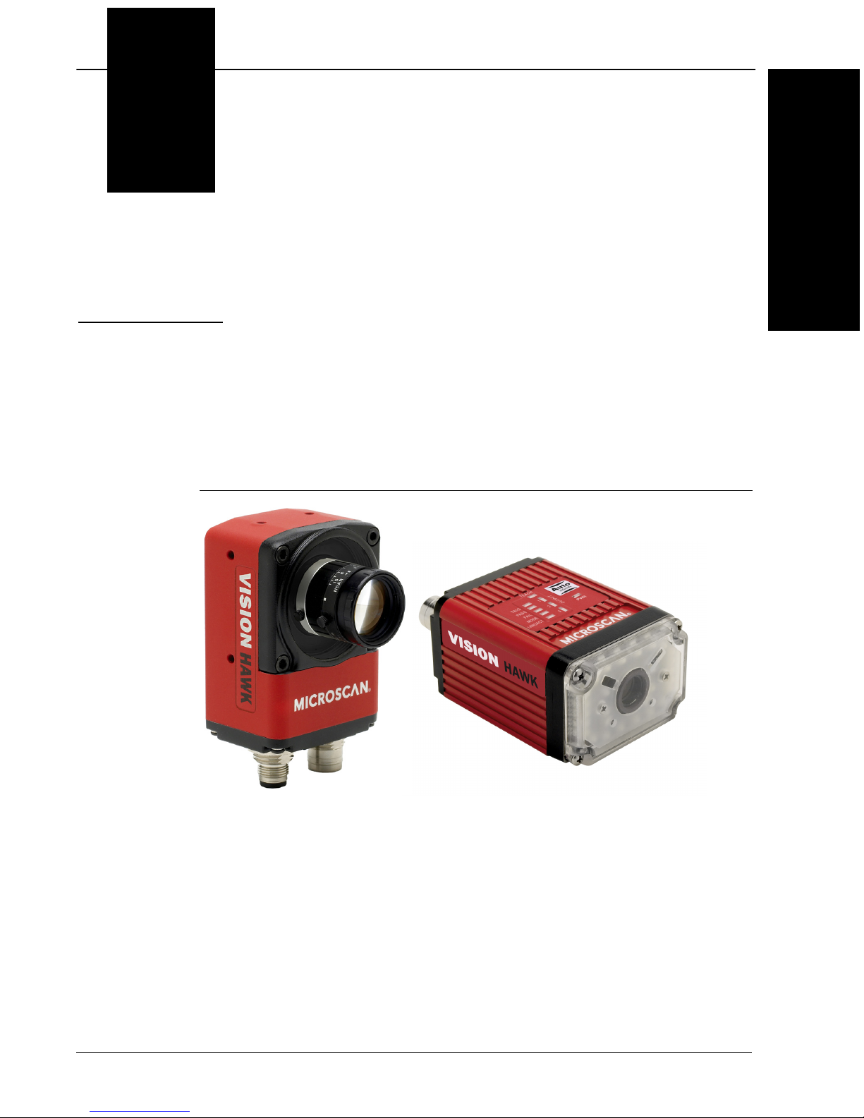
CHAPTER 1 Introduction
FIGURE 1–1. Vision HAWK Smart Camera, C-Mount and Standard Models
1
Introduction
Vision HAWK Smart Camera Guide 1-1
Page 8

Chapter 1 Introduction
Product Summary
The Vision HAWK Smart Camera is a compact industrial smart camera
that provides powerful machine vision capabilities with a small form factor
and intuitive software interface. The Vision HAWK is designed for
industrial environments where IP65/67 enclosure and rugged M12
connectivity are required.
Fully-integrated I/O and communications make the Vision HAWK easy to
incorporate in virtually any machine vision application. Patented liquid
lens autofocus and modular optical zoom enables the Vision HAWK to
inspect objects at distances from 33 mm to 2 m and beyond.
Pressing the AutoVISION button at the back of the Vision HAWK enables
real time dynamic autofocus. When an object is centered in the field of view
and the AutoVISION button is pressed, the camera automatically adjusts
focal distance and sets internal parameters to optimize image captures.
AutoVISION software, designed for use with the Vision HAWK, provides an
intuitive interface, step-by-step configuration, and a library of presets that
allow easy setup and deployment. For more complex vision applications,
the system can be upgraded from AutoVISION to Visionscape.
Features and Benefits
• Color and monochrome models available
• Standard and C-Mount models available
• SXGA (1280 x 960), WVGA (752 x 480), and WUXGA (2048 x 1088,
C-Mount model only) resolutions available
• World’s first vision system with liquid lens autofocus (standard models)
• Integrated lighting (standard models)
• Integrated Ethernet
• Flexible programming options for custom applications
• AutoVISION button for automatic targeting, calibration, and triggering
• Simplified configuration with AutoVISION software
• Fully scalable with Visionscape
• Applications can be ported to Visionscape PC-based machine vision
1-2 Vision HAWK Smart Camera Guide
Page 9

Applications
• Automotive assembly verification
• Part identification
• Label positioning
• Contents verification
• Electronics assembly verification and identification
• Semiconductor packaging and component inspection
• Auto ID (Data Matrix and other 2D symbologies, 1D, OCR)
Package Contents
Applications
1
Introduction
Before you install AutoVISION software and connect your Vision HAWK
Smart Camera, please take a moment to confirm that the following items
are available:
• Vision HAWK Smart Camera — Your package contains one of the
available models listed in Table 1–1
• Microscan Tools Drive — USB flash drive containing AutoVISION software
• Required accessories such as a power supply or power cable
Vision HAWK Smart Camera Guide 1-3
Page 10

Chapter 1 Introduction
Vision HAWK Smart Camera Models
Table 1–1 lists and describes the Vision HAWK Smart Camera models.
TABLE 1–1. Vision HAWK Smart Camera Models
Part Number Vision HAWK Smart Camera Model
GMV-6800-1000G Vision HAWK, SXGA, AutoVISION, C-Mount
GMV-6800-1002G Vision HAWK, SXGA, AutoVISION+Visionscape, C-Mount
GMV-6800-1004G Vision HAWK, SXGA, AutoVISION+Verification/OCV, C-Mount
GMV-6800-1006G Vision HAWK, SXGA, AutoVISION+Visionscape+Verification/OCV, C-Mount
GMV-6800-1010G Vision HAWK, WVGA, AutoVISION, C-Mount
GMV-6800-1012G Vision HAWK, WVGA, AutoVISION+Visionscape, C-Mount
GMV-6800-1014G Vision HAWK, WVGA, AutoVISION+Verification/OCV, C-Mount
GMV-6800-1016G Vision HAWK, WVGA, AutoVISION+Visionscape+Verification/OCV, C-Mount
GMV-6800-1022G Vision HAWK, SXGA, Color, AutoVISION+Visionscape, C-Mount
GMV-6800-1030G Vision HAWK, WUXGA, Mono, AutoVISION, C-Mount
GMV-6800-1032G Vision HAWK, WUXGA, Mono, AutoVISION+Visionscape, C-Mount
GMV-6800-1034G Vision HAWK, WUXGA, Mono, AutoVISION+Verification/OCV, C-Mount
GMV-6800-1036G Vision HAWK, WUXGA, Mono, AutoVISION+Visionscape+Verification/OCV, C-Mount
GMV-6800-1200G Vision HAWK, SXGA, Built-In Lighting, AutoVISION, 30° Lens
GMV-6800-1202G Vision HAWK, SXGA, Built-In Lighting, AutoVISION+Visionscape, 30° Lens
GMV-6800-1204G Vision HAWK, SXGA, Built-In Lighting, AutoVISION+Verification/OCV, 30° Lens
GMV-6800-1206G Vision HAWK, SXGA, Built-In Lighting, AutoVISION+Visionscape+Verification/OCV, 30° Lens
GMV-6800-1210G Vision HAWK, WVGA, Built-In Lighting, AutoVISION, 30° Lens
GMV-6800-1212G Vision HAWK, WVGA, Built-In Lighting, AutoVISION+Visionscape, 30° Lens
GMV-6800-1214G Vision HAWK, WVGA, Built-In Lighting, AutoVISION+Verification/OCV, 30° Lens
GMV-6800-1216G Vision HAWK, WVGA, Built-In Lighting, AutoVISION+Visionscape+Verification/OCV, 30° Lens
GMV-6800-1222G Vision HAWK, SXGA, Built-In Lighting, Color, AutoVISION+Visionscape, 30° Lens
GMV-6800-1300G Vision HAWK, SXGA, Built-In Lighting, AutoVISION, 45° Lens
GMV-6800-1302G Vision HAWK, SXGA, Built-In Lighting, AutoVISION+Visionscape, 45° Lens
GMV-6800-1304G Vision HAWK, SXGA, Built-In Lighting, AutoVISION+Verification/OCV, 45° Lens
GMV-6800-1306G Vision HAWK, SXGA, Built-In Lighting, AutoVISION+Visionscape+Verification/OCV, 45° Lens
GMV-6800-1310G Vision HAWK, WVGA, Built-In Lighting, AutoVISION, 45° Lens
GMV-6800-1312G Vision HAWK, WVGA, Built-In Lighting, AutoVISION+Visionscape, 45° Lens
GMV-6800-1314G Vision HAWK, WVGA, Built-In Lighting, AutoVISION+Verification/OCV, 45° Lens
GMV-6800-1316G Vision HAWK, WVGA, Built-In Lighting, AutoVISION+Visionscape+Verification/OCV, 45° Lens
GMV-6800-1322G Vision HAWK, SXGA, Built-In Lighting, Color, AutoVISION+Visionscape, 45° Lens
GMV-6800-1400G Vision HAWK, SXGA, Built-In Lighting, AutoVISION, 12° Lens
GMV-6800-1402G Vision HAWK, SXGA, Built-In Lighting, AutoVISION+Visionscape, 12° Lens
1-4 Vision HAWK Smart Camera Guide
Page 11
Part Number Structure
TABLE 1–1. Vision HAWK Smart Camera Models
Part Number Vision HAWK Smart Camera Model
GMV-6800-1404G Vision HAWK, SXGA, Built-In Lighting, AutoVISION+Verification/OCV, 12° Lens
GMV-6800-1406G Vision HAWK, SXGA, Built-In Lighting, AutoVISION+Visionscape+Verification/OCV, 12° Lens
GMV-6800-1410G Vision HAWK, WVGA, Built-In Lighting, AutoVISION, 12° Lens
GMV-6800-1412G Vision HAWK, WVGA, Built-In Lighting, AutoVISION+Visionscape, 12° Lens
GMV-6800-1414G Vision HAWK, WVGA, Built-In Lighting, AutoVISION+Verification/OCV, 12° Lens
GMV-6800-1416G Vision HAWK, WVGA, Built-In Lighting, AutoVISION+Visionscape+Verification/OCV, 12° Lens
GMV-6800-1422G Vision HAWK, SXGA, Built-In Lighting, Color, AutoVISION+Visionscape, 12° Lens
GMV-6800-1500G Vision HAWK, SXGA, Built-In Lighting, AutoVISION, 15° Lens
GMV-6800-1502G Vision HAWK, SXGA, Built-In Lighting, AutoVISION+Visionscape, 15° Lens
GMV-6800-1504G Vision HAWK, SXGA, Built-In Lighting, AutoVISION+Verification/OCV, 15° Lens
GMV-6800-1506G Vision HAWK, SXGA, Built-In Lighting, AutoVISION+Visionscape+Verification/OCV, 15° Lens
GMV-6800-1510G Vision HAWK, WVGA, Built-In Lighting, AutoVISION, 15° Lens
GMV-6800-1512G Vision HAWK, WVGA, Built-In Lighting, AutoVISION+Visionscape, 15° Lens
GMV-6800-1514G Vision HAWK, WVGA, Built-In Lighting, AutoVISION+Verification/OCV, 15° Lens
GMV-6800-1516G Vision HAWK, WVGA, Built-In Lighting, AutoVISION+Visionscape+Verification/OCV, 15° Lens
GMV-6800-1522G Vision HAWK, SXGA, Built-In Lighting, Color, AutoVISION+Visionscape, 15° Lens
1
Introduction
Part Number Structure
GMV
General
Machine
Vision
6800
Vision
HAWK
Comm Lens Sensor Software RoHS
1 = Ethernet
0 = C-Mount
2 = 30° Lens
3 = 45° Lens
4 = 12° Lens 3 = CMOS
5 = 15° Lens
0 = CCD
(SXGA) Mono
1 = CMOS
(WVGA) Mono
2 = CCD
(SXGA) Color
(WUXGA)
Mono
0 = AutoVISION
2 = AutoVISION +
Visionscape
4 = AutoVISION +
Verification/OCV
6 = AutoVISION +
Visionscape +
Verification/OCV
G = RoHScompliant
Vision HAWK Smart Camera Guide 1-5
Page 12

Chapter 1 Introduction
1-6 Vision HAWK Smart Camera Guide
Page 13
2
CHAPTER 2 System Components
This section contains information about system components as well as
information to help you connect the Vision HAWK Smart Camera. Specific
information describes connectors, adapters, cables, pinouts, and signals.
2
System Components
Note: There are no user-serviceable parts inside.
Hardware Components
Table 2-1 lists Vision HAWK Smart Camera hardware components.
TABLE 2–1. Vision HAWK Smart Camera Hardware Components
Part Number Description
Demo Kit
98-000215-01 Demo Kit (Power Supply, Camera Stand, Ethernet Host Cable, Carrying Case, Documentation)
Power Supplies
97-000012-01
97-000012-04 Power Supply, M12 12 pin Plug, 1.3m
Communication Devices and Cables
98-000103-01 QX-1 Interface Device
61-000148-02 Cordset, Common, M12 12 Pin, Socket to M12 12 Pin Plug, 3M
61-000162-02 Cordset, Common, M12 12 Pin, Socket to M12 12 Pin Plug, 1M
61-000153-02 Cordset, Host, Serial M12 12 pin Socket to DB9 Socket, 1M
61-000164-02 Cordset, Host, Serial, M12 12 pin Socket to DB9 Socket, 3M
61-000152-02 Cordset, Host, Serial, M12 12 pin Plug to DB9 Socket, 1M
Power Supply, M12 12-pin Socket, 1.3 m
Vision HAWK Smart Camera Guide 2-1
Page 14

Chapter 2 System Components
TABLE 2–1. Vision HAWK Smart Camera Hardware Components (Continued)
Part Number Description
61-000165-02 Cordset, Host, Serial M12 12 pin Plug to DB9 Socket, 3M
61-000163-02 Cordset, Host, Ethernet, M12 8 pin Plug to RJ45, 3M
61-000160-02 Cordset, Host, Ethernet, M12 8 pin Plug to RJ45, 1M
61-000166-02 Cordset, M12 12 Pin Plug to Flying Leads, 3M
61-000167-02 Cordset, M12 12 Pin Socket to Flying Leads, 3M
61-000207-01 Cordset, C-Mount-to-Smart Series Light
FIS-0210-0001G MS-Connect 210, Connectivity Box with Display
FIS-0210-0002G MS-Connect 210, Connectivity Box
FIS-0210-0003G MS-Connect 210, Connectivity Box with Display and Ethernet
FIS-0210-0004G MS-Connect 210, Connectivity Box with Ethernet
98-000013-04 Relay Module, 120VAC, 3 Amp Output, Series 70, Type SM, for MS-Connect 210
98-000013-05 Relay Module, 240VAC, 3 Amp Output, Series 70, Type SM for MS-Connect 210
98-000013-06 Relay Module, 24VDC, 3 Amp Output, Series 70, Type SM for MS-Connect 210
Accessories
98-000143-01 Adapter Plate Kit
98-000148-01 L-Bracket Kit
98-000144-01 Right Angle Mirror Kit
98-000146-01 Window Replacement Kit
98-000147-04 12° Lens Kit
98-000147-01 15° Lens Kit
98-000147-02 30° Lens Kit
98-000147-03 45° Lens Kit
98-000205-01 Glass Window Kit with Infrared (IR) Filter
98-000206-01 Glass Window Kit
98-500006-01 Mounting Plate Kit, Flat, Custom Surfaces
20-610024-01 Trigger Connector, 4-pin Plug (screw terminal and field-wireable) (for self-wiring)
98-000037-01 Extension Kit, All Cameras, 6 inch
98-000054-01 Kit, Mounting Stand Base Plate, Small
98-000016-01 Mounting Arm/Adapter Kit, 6 inch
99-000056-01 Accessory, Bracket, DOAL 50 to Vision HAWK
99-000058-01 Accessory, Bracket, DOAL 75 to Vision HAWK
99-000060-01 Accessory, Bracket, DOAL 100 to Vision HAWK
99-000061-01 Accessory, Bracket, DOAL to C-MOUNT Vision HAWK
99-000050-01 Accessory, Bracket,R-100 to Vision HAWK
99-000052-01 Accessory, Bracket,R-60/70 to Vision HAWK
99-000049-01 Accessory, Bracket,R-100 to C-MOUNT Vision HAWK
99-000051-01 Accessory, Bracket,R-60/70 to C-MOUNT Vision HAWK
98-92800471 5MM Extension Tube for C-Mount Lenses
98-CO206 Lens Extension Tube Set 0.5, 1, 5, 10, 20, 40mm
2-2 Vision HAWK Smart Camera Guide
Page 15

TABLE 2–1. Vision HAWK Smart Camera Hardware Components (Continued)
Part Number Description
98-92800571 Lens 8mm F/1.4-16, FT 25.5mm P 0.5mm, 2/3" C-MNT
98-92800572 Lens 12mm F/1.8-16, FT 25.5mm P 0.5mm, 2/3" C-MNT
98-92800573 Lens 16mm F/1.4-16, FT 25.5mm P 0.5mm, 2/3" C-MNT
98-92800574 Lens 25mm F/1.6-16, FT 25.5mm P 0.5mm, 2/3" C-MNT
98-92800575 Lens 35mm F/2.1-22, FT 25.5mm P 0.5mm, 2/3" C-MNT
98-92800576 Lens 50mm F/2.8-22, FT 25.5mm P 0.5mm, 2/3" C-MNT
98-92800577 Lens 75mm F/3.9-32, FT 25.5mm P 0.5mm, 2/3" C-MNT
98-92800311 Lens, Skylight UV Filter 25.5mm Thread
98-92800371 Polarizing Filter 25.5mm Thread
98-000218-01 Lens Protection Housing, Standard Length (up to 48 mm)
98-000226-01 Lens Protection Housing, Long (up to 72 mm)
Object Detectors
99-000020-01 Photo Sensor, M12 4pin Plug, NPN, Dark Off, 2m
99-000020-02 Photo Sensor, M12 4-pin Plug, NPN, Dark On, 2 m
Documentation
37-000010-01
Note: Additional hardware components are available in the Microscan Product Pricing Catalog.
Microscan Tools Drive (Software, User Manuals, Quick Start Guides, Configuration Guides, links to
other documents on Microscan website)
Hardware Components
2
System Components
Vision HAWK Smart Camera Guide 2-3
Page 16
Chapter 2 System Components
Standard Vision HAWK Front
Figure 2-1 shows the front of the Vision HAWK Smart Camera.
FIGURE 2–1. Front
Standard Vision HAWK Base
Figure 2–2 shows the base of the Vision HAWK Smart Camera.
FIGURE 2–2. Base
2-4 Vision HAWK Smart Camera Guide
Page 17
Standard Vision HAWK Side
Figure 2-3 shows the side of the Vision HAWK Smart Camera.
FIGURE 2–3. Side
Hardware Components
2
System Components
Standard Vision HAWK Back
Figure 2-4 shows the back of the Vision HAWK Smart Camera.
FIGURE 2–4. Back
Vision HAWK Smart Camera Guide 2-5
Page 18
Chapter 2 System Components
Vision HAWK C-Mount Front
Figure 2-5 shows the front of the Vision HAWK C-Mount Smart Camera.
FIGURE 2–5. Front
Vision HAWK C-Mount Base
Figure 2–6 shows the top of the Vision HAWK C-Mount Smart Camera.
FIGURE 2–6. Top
2-6 Vision HAWK Smart Camera Guide
Page 19
Vision HAWK C-Mount Side
Figure 2-7 shows the side of the Vision HAWK C-Mount Smart Camera.
FIGURE 2–7. Side
Hardware Components
2
System Components
Vision HAWK C-Mount Back
Figure 2-8 shows the back of the Vision HAWK C-Mount Smart Camera.
FIGURE 2–8. Back
Vision HAWK Smart Camera Guide 2-7
Page 20

Chapter 2 System Components
Important Label Information
Each Vision HAWK Smart Camera has its own label, which contains
important information about that camera.
• P/N – The Microscan part number of your Vision HAWK Smart
Camera.
• S/N — The serial number of your Vision HAWK Smart Camera.
• MAC — The MAC address of your Vision HAWK Smart Camera.
2-8 Vision HAWK Smart Camera Guide
Page 21

Mounting and Wiring the Vision HAWK Smart Camera
Mounting
holes
1
3
2
1
4
5
6
3
2
1
4
5
6
Standard Vision HAWK
Vision HAWK C-Mount
For most C-Mount lenses:
• Loosen all lens screws to
allow free lens
movement.
• Install first set screw in
the available slot.
• Remove one lens screw
and install second set
screw to allow for
adjustment.
Important: Configuration
details may vary by lens
model.
Mounting and Wiring the Vision HAWK Smart Camera
Important: Pin 9 (Host RxD) must be tied to ground (Pin 7) when using a
flying lead cable and the serial port is not being used. The camera may not
boot to completion if RxD is not grounded. Isolate unused wires. The ends
of unused wires must not touch each other.
• Mount the camera (1) securely as required by the application.
• Connect the Ethernet cable (2) from “B” on the camera (1) to the
network.
• Connect the power supply cable (3) to “3” on the QX-1 (4).
• Connect the trigger (5) to “T” on the QX-1 (4).
• Connect the “Common” cable (6) from “A” on the camera (1) to “2” on
the QX-1 (4).
• Plug in the power supply (3).
2
System Components
Vision HAWK Smart Camera Guide 2-9
Page 22
Chapter 2 System Components
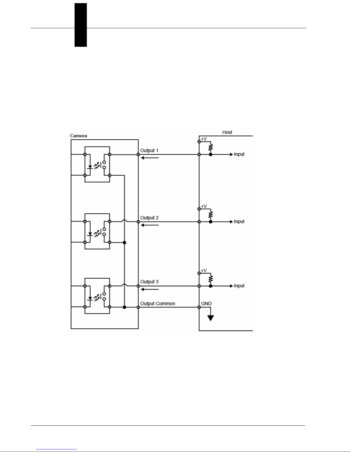
Optoisolated Outputs
The reader has optoisolated outputs that can transfer signals from the
camera to peripherals. Outputs can be configured as either NPN or PNP,
but NPN and PNP cannot be mixed in a system, because the output
common is shared by all outputs.
NPN Output for Host Input
2-10 Vision HAWK Smart Camera Guide
Page 23

Mounting and Wiring the Vision HAWK Smart Camera
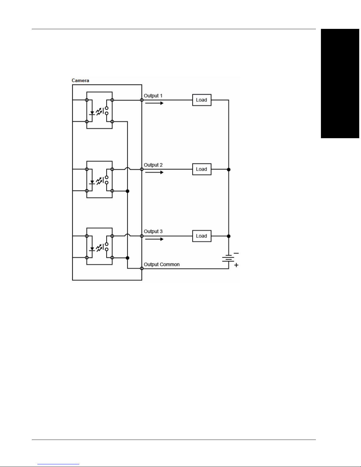
NPN Output for External Load
2
System Components
Vision HAWK Smart Camera Guide 2-11
Page 24
Chapter 2 System Components
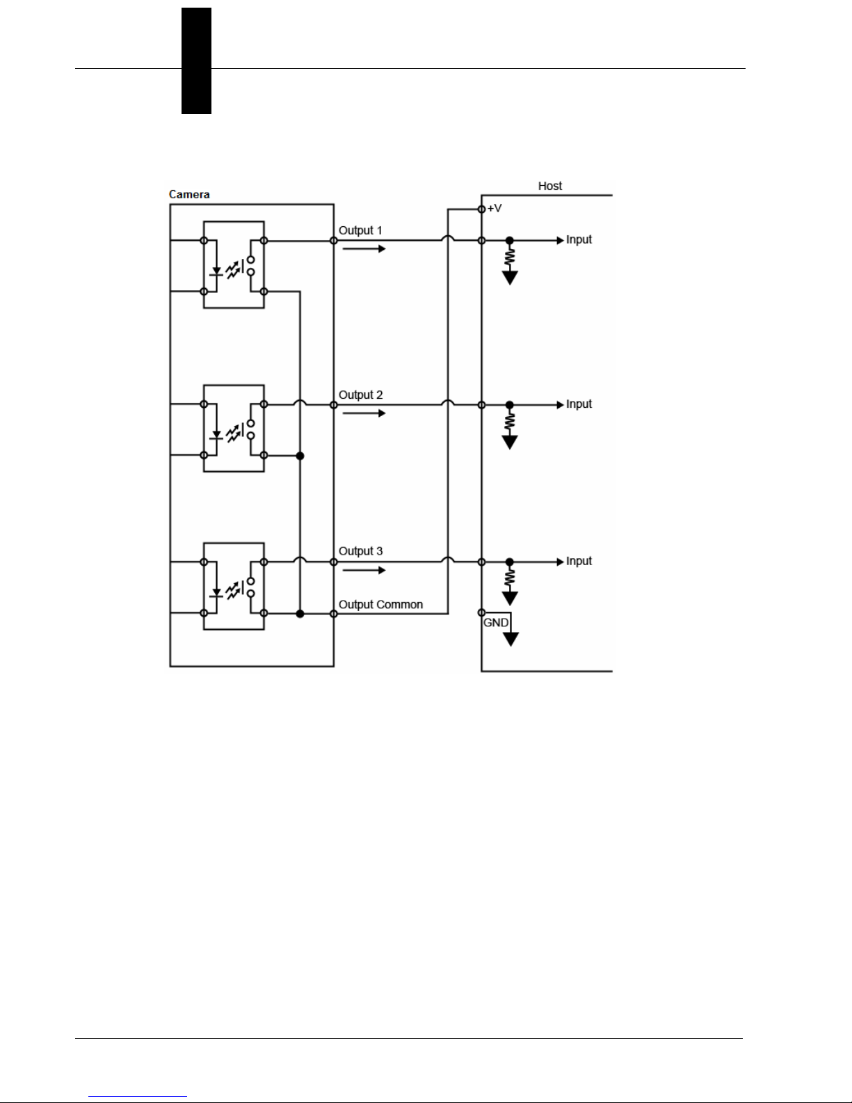
PNP Output for Host Input
2-12 Vision HAWK Smart Camera Guide
Page 25
Mounting and Wiring the Vision HAWK Smart Camera
PNP Output for External Load
2
System Components
Vision HAWK Smart Camera Guide 2-13
Page 26
Chapter 2 System Components
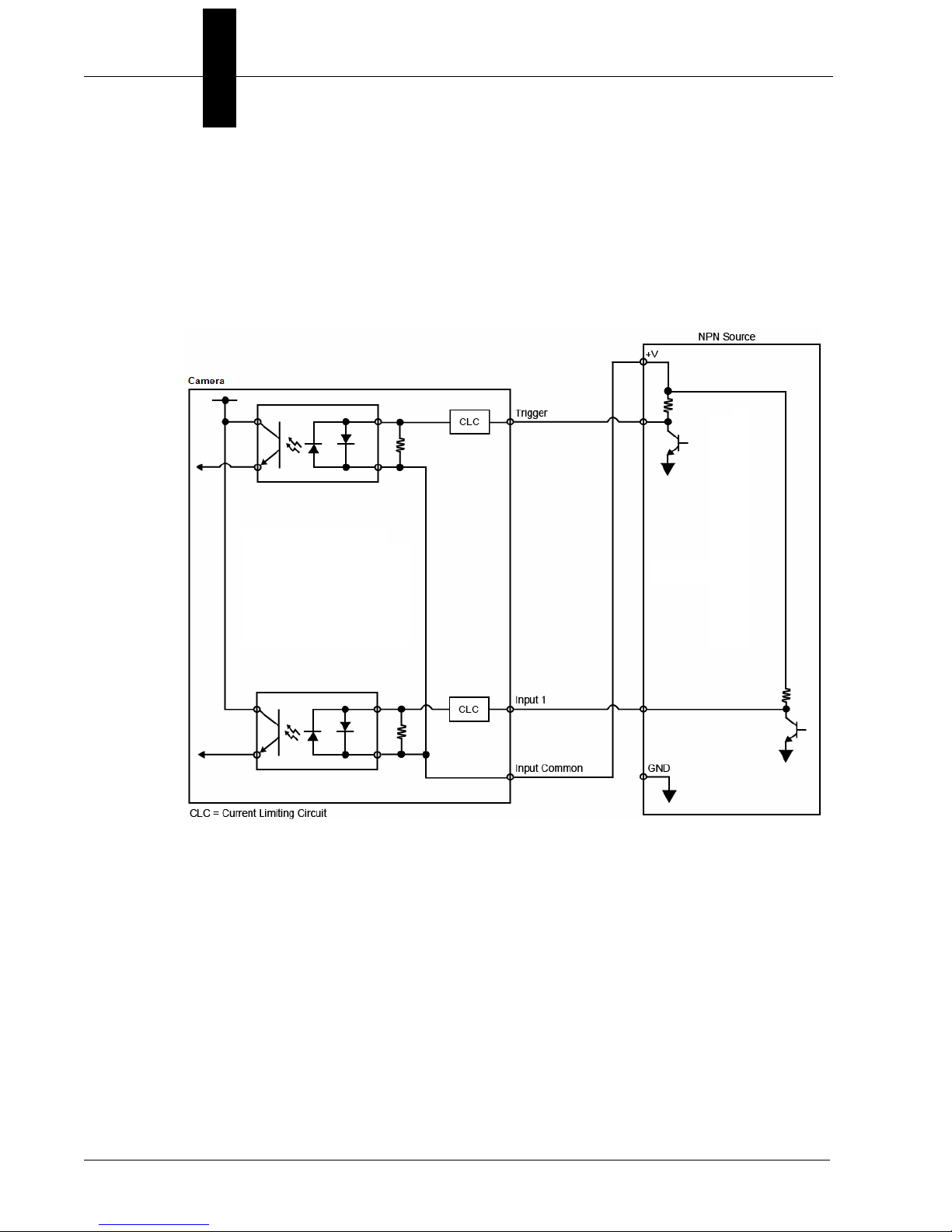
Optoisolated Inputs
All discrete inputs are optoisolated. Inputs can be configured as either
NPN or PNP, but NPN and PNP cannot be mixed in a system, because
the input common is shared by all inputs.
NPN
2-14 Vision HAWK Smart Camera Guide
Page 27
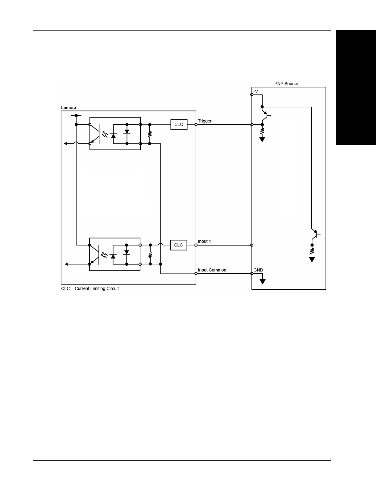
PNP
Mounting and Wiring the Vision HAWK Smart Camera
2
System Components
Vision HAWK Smart Camera Guide 2-15
Page 28
Chapter 2 System Components
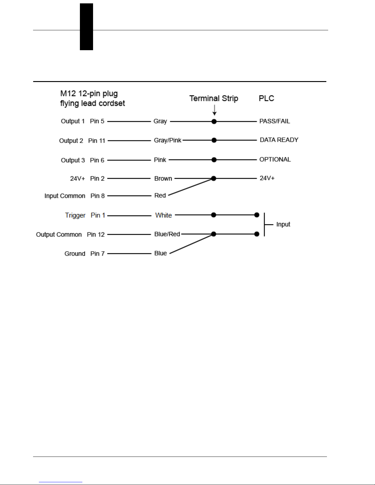
Input/Output Wiring
2-16 Vision HAWK Smart Camera Guide
Page 29
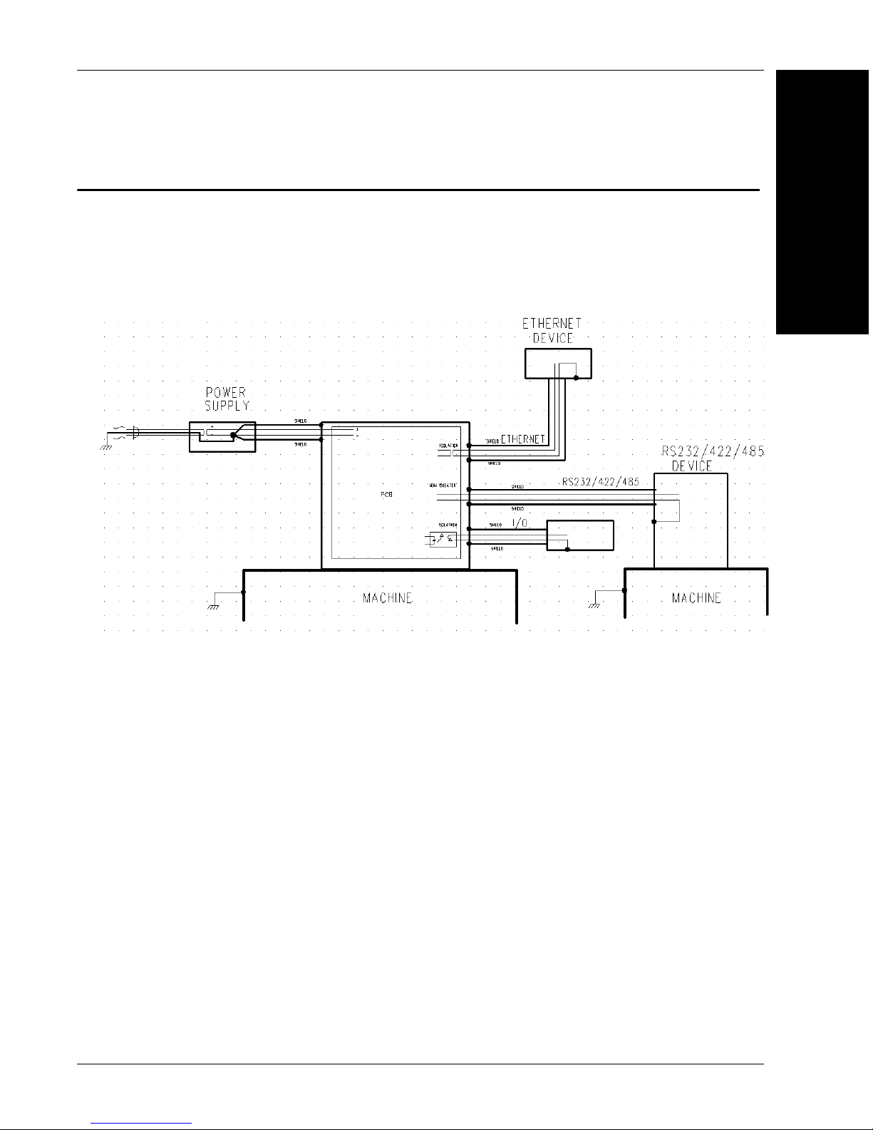
Ground and Shield Considerations
An earth ground is provided through the cable shields and chassis of the imager.
Vision HAWK
Proper grounding is necessary for operator safety, noise reduction, and
the protection of equipment from voltage transients. Buildings, including
any steelwork, all circuits, and all junction boxes must be grounded
directly to an earth ground in compliance with local and national electrical
codes.
Ground and Shield Considerations
2
System Components
Ground Loops
Ground loops (signal degradation due to different ground potentials in
communicating devices) can be eliminated or minimized by ensuring that
both the host, imager, and their power supplies are connected to a
common earth ground.
Vision HAWK Smart Camera Guide 2-17
Page 30
Chapter 2 System Components
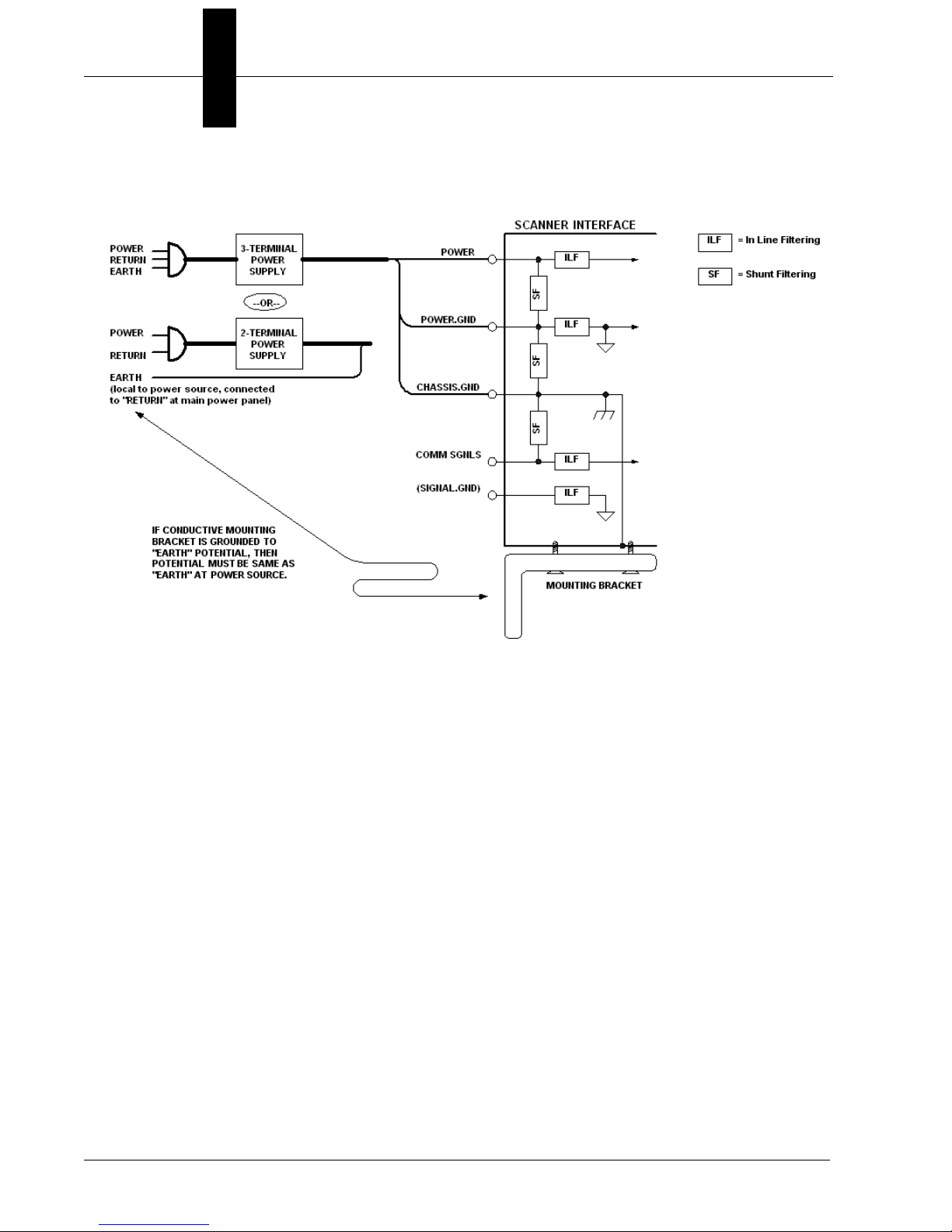
Expected Power and Ground Connections for Proper Operation
Grounding Notes:
• Ensure that mounting bracket “Earth” is at the same potential as
power source “Earth”.
• Supply “Return” and “Earth” ground must be stable, low-impedance
reference points.
• “2-Terminal Power Supply” must still provide an “Earth” connection to
the imager.
• “Signal Ground” can be used for communications and/or discrete signal
ground reference. It must not be used as Power Ground or Earth
Ground.
2-18 Vision HAWK Smart Camera Guide
Page 31

Power Requirements
Refer to Table 2-3 when determining the power supply requirements for
your camera.
TABLE 2–3. Camera Power Requirements
Power Requirements
2
Component
Vision HAWK Smart Camera, CCD,
SXGA
Vision HAWK Smart Camera, CMOS,
SXGA
Vision HAWK C-Mount Smart Camera,
CCD, SXGA
Vision HAWK C-Mount Smart Camera,
CMOS, WVGA
Vision HAWK C-Mount Smart Camera,
CMOS, WUXGA
System Components
5-28VDC, 200mV p-p max ripple,
170mA at 24VDC (typ.)
15.5 watts (max.)
5-28VDC, 200mV p-p max ripple,
135mA at 24VDC (typ.)
13 watts (max.)
5-28VDC, 200mV p-p max ripple,
170mA at 24VDC (typ.)
7 watts (max.)
5-28VDC, 200mV p-p max ripple,
135mA at 24VDC (typ.)
4 watts (max.)
5-28VDC, 200mV p-p max ripple,
140mA at 24VDC (typ.)
5.7 watts (max.)
Vision HAWK Smart Camera Guide 2-19
Page 32

Chapter 2 System Components
TRIG = Trigger Status
PASS/FAIL = Inspection Status
MODE = Camera Status
LINK/ACT = Link Activity Status
Power Status
Outputs 1, 2, 3
Status Indicators
The top of the Vision HAWK Smart Camera has multiple LEDs that indicate
different trigger, inspection, camera, communication, and power states.
On Steady Continuous Trigger
TRIG
PASS/FAIL
MODE
LINK/ACT
PWR
OUTPUTS
Additional User Feedback
Off Waiting for Trigger Event
On Flashing Trigger Event
On Active State
Off Inactive State
On Steady Unit Ready
Off Unit Not Ready
On Steady Link Established
Off No Link/Activity
On Flashing Link Established and Activity on Link
On Power On
Off No Power Applied to Unit
On Signal Sent to External Output
Off No Signal Sent to External Output
• Green Flash – A green flash from the front of the unit indicates a Good Read.
• Red X Targeting Pattern – The red X targeting pattern from the front of
the unit allows the user to center an object in the camera’s field of view.
• Beeper – The beeper is an audible verification that either a Pass or a
Fail has occurred.
2-20 Vision HAWK Smart Camera Guide
Page 33

AutoVISION Button
AutoVISION Button
2
The AutoVISION Button has three positions, selectable by the length of
time the button is held down, and indicated by one, two, or three beeps
and LED flashes in succession. It can also be used to send a trigger
signal when Send Trigger is checked in AutoVISION software’s Connect
view. When the trigger functionality is enabled, pushing the AutoVISION
Button triggers the camera to capture an image.
1st Position: Red Targeting Pattern
The first AutoVISION Button position turns the targeting system on.
This overrides any other targeting modes that have been configured.
2nd Position: Auto Calibration
The second AutoVISION Button position starts the Auto Calibration
process, which selects the appropriate photometry and focus settings
for the camera. The selected values are then saved for power-on.
System Components
3rd Position: Teach
The third AutoVISION Button position sets the Match String to the
next OCR string or symbol data that is decoded.
Vision HAWK Smart Camera Guide 2-21
Page 34

Chapter 2 System Components
1
3
8
6
7
2
See Appendix A, Connector Pinouts, for
Vision HAWK pin assignments.
Setting Up a Job in AutoVISION
AutoVISION is a critical component of the Vision HAWK’s functionality.
Designed for use with the Vision HAWK, AutoVISION provides an intuitive
interface, step-by-step configuration, and a library of presets that allow
easy setup and deployment. For more complex vision applications, the
system can be upgraded from AutoVISION to Visionscape.
1. Configure Vision HAWK hardware.
Item Description Part Number
1 Vision HAWK Smart Camera GMV-6800-XXXXG
2 QX-1 Interface Device 98-000103-02
3 Cordset, Common, M12 12-pin Plug to M12 12-pin
Socket, 1 m
4 Cordset, Host, Serial, M12 12-pin Plug to DB9, 1 m 61-000152-01
5 Cordset, Host, Serial, M12 12-pin Socket to DB9, 1 m 61-000153-01
2-22 Vision HAWK Smart Camera Guide
Note: Additional cables available in the Microscan Product Pricing Catalog.
6 Power Supply, M12 12-pin Socket, 1.3 m
7 Cordset, Host, Ethernet, M12 8-pin Plug to RJ45, 1 m
8 Trigger, M12 4-pin Plug, NPN, Dark On, 2 m 99-000020-02
61-000162-01
97-000012-01
61-000160-03
Page 35

Setting Up a Job in AutoVISION
– Mount the camera as required by the application.
– Connect the Ethernet cable from "B" on the camera to the
network.
– Connect the power supply to "3" on the QX-1.
– Connect the photo sensor to "T" on the QX-1.
– Connect the "Common" cable to "2" on the QX-1 and "A" on the
camera.
– Plug in the power supply.
2. Select your Vision HAWK in the AutoVISION Connect view, create a
job, and adjust camera settings.
AutoVISION's Connect view allows you to select your device and
configure its settings, and to create a new job. The Select Device
dropdown menu provides a list of available devices. Hover the mouse
over a device to see its details.
2
System Components
Vision HAWK Smart Camera Guide 2-23
Page 36

Chapter 2 System Components
Modify camera settings in the
Details area at the left of the
Connect view.
Create, Load, or Upload a job
using the buttons in the center
of the Connect view.
Click the lock icon to take control of the camera. When you have
control of the camera, the Modify button will appear beneath the
camera settings. Click the Modify button to adjust camera settings.
Note: The default IP address of the camera is: 192.168.0.10. Be sure
your PC is on the same subnet (192.168.0.100, for example).
Important: When modifying camera settings, you will need to enter a
username and password for the camera if a password has been defined.
2-24 Vision HAWK Smart Camera Guide
Page 37

Setting Up a Job in AutoVISION
Once you have selected your camera, adjusted its settings, and
created a new job, you will move to the Image view. This view allows
you to Auto Calibrate the camera, and to manually adjust the
camera's Exposure, Gain, and Focus, and also to set the Lighting
Mode (On, Off, or Strobe).
2
System Components
3. Edit the Job in AutoVISION.
After you have created a new job, loaded a job from your PC, or
uploaded a job from the camera, you will proceed to the Edit view to
refine your machine vision job. The Camera parameters below the
captured image allow you to set Gain, Exposure, Focus, Trigger, and
Lighting. Inspection Outputs options allow you to connect your job to
the outside world. This is also the view where you can add multiple
tools to the job. The tool icons are located above the main view area.
Vision HAWK Smart Camera Guide 2-25
Page 38

Chapter 2 System Components
4. Run the Job in AutoVISION.
Going to the Run view will automatically download your job to the
camera and start it running.
5. Save the Job.
Click the Save to Camera icon on the File menu bar to save the job
to the Vision HAWK.
2-26 Vision HAWK Smart Camera Guide
Page 39

Trigger Debounce
Trigger Debounce
2
Trigger Debounce
change – a common issue with relays that have some intermittent contact while engaging.
is the ability of the system to accomodate switching noise on a trigger state
Trigger overruns (when the vision system is triggered faster than the device can process)
can be avoided by increasing the “debounce” time in the camera definition file located in
the C:\Microscan\Vscape\Drivers\CamDefs directory.
The IO Line Debounce High Time and IO Line Debounce Low Time can be added to the
file as in the example below. The default debounce time is 1 ms (1,000 μs).
Note: Although the value entered for the "IO Line Debounce Time" is in microseconds, it
will only be rounded up to a millisecond value. For example, entering the value 1001 will
resolve to 2 ms; entering a value of 2800 will resolve to 3 ms.
The min value for "IO Line Debounce Time" is 0, which disables software debounce
altogether. The maximum value is 100000 (100 ms).
Camera Definition File Example
// Camera Definition File
// Version: 1.10
Camera Name VisionHAWK 752x480 CMOS // Name Displayed
in Camdef Selection Dialog
Digitizer Type 4000 // Number
associated with VisionHawk CMOS Camera
Stride 752 // Image Width
Rows 480 // Image Height
X Offset 0 // Image X Offset
Y Offset 0 // Image Y Offset
Bits Per Pixel 8 // Bits that represent Pixel Value
Pixel Type 0 // Type of Pixel: MONOCHROME=0,
COLOR_RGB=1, COLOR_BGR=2, COLOR_BAYGR8=3, COLOR_BAYRG8=4, COLOR_BAYGB8=5,
COLOR_BAYBG8=6, COLOR_HSI=7
Image Structure 1 // Pixel Organization: Packed=1, TwoPlanes =
2, ThreePlanes = 3
Async Control 1 // Controllable shutter time. Usually
using a pulse width specified in usecs
Usecs Per Frame 16667 // Fastest time to acquire a frame: 60 FPS
for VisionHawk CMOS Camera // -1 Disables timeout feature
// IO Configuration
GPIO Edit Mask 0x0000
GPIO Defaults 0x0001 // 1 General Purpose Input 3 General Purpose
Outputs
GPIO Count 4
GPIO Inputs 1
GPIO Outputs 3
Sensors 1 // One input dedicated
to Trigger signal
Strobes 0
Virtual IO 2048
IO Line Debounce High Time 2000 //usecs
IO Line Debounce Low Time 2000 //usecs
// Focus & Photometry Ranges
Gain Dflt 20
Gain Min 0
System Components
Vision HAWK Smart Camera Guide 2-27
Page 40

Chapter 2 System Components
Gain Max 100 // 0 to 100%
Exp Dflt 400
Exp Min 25
Exp Max 100000 // 1/10 to 1/40,000
Focus Dflt 400
Focus Min 100
Focus Max 4000 // 1 to 40 inches
// Lens Configuration
C-Mount 0 // 0 = false, 1 = true
2-28 Vision HAWK Smart Camera Guide
Page 41

3
CHAPTER 3 Optics and Lighting
This section describes the optical and illumination characteristics of the
Vision HAWK Smart Camera.
3
Optics and Lighting
Vision HAWK Smart Camera Guide 3-1
Page 42

Chapter 3 Optics and Lighting
Optics
P/N / Model Sensor Shutter Focal Range
GMV-6800-1000G
GMV-6800-1002G
GMV-6800-1004G
GMV-6800-1006G
GMV-6800-1010G
GMV-6800-1012G
GMV-6800-1014G
GMV-6800-1016G
GMV-6800-1022G
GMV-6800-1030G
GMV-6800-1032G
GMV-6800-1034G
GMV-6800-1036G
GMV-6800-1200G
GMV-6800-1202G
GMV-6800-1204G
GMV-6800-1206G
GMV-6800-1210G
GMV-6800-1212G
GMV-6800-1214G
GMV-6800-1216G
GMV-6800-1222G
GMV-6800-1300G
GMV-6800-1302G
GMV-6800-1304G
GMV-6800-1306G
GMV-6800-1310G
GMV-6800-1312G
GMV-6800-1314G
GMV-6800-1316G
GMV-6800-1322G
GMV-6800-1400G
GMV-6800-1402G
GMV-6800-1404G
GMV-6800-1406G
GMV-6800-1410G
GMV-6800-1412G
GMV-6800-1414G
GMV-6800-1416G
GMV-6800-1422G
GMV-6800-1500G
GMV-6800-1502G
GMV-6800-1504G
GMV-6800-1506G
-6800-1510G
GMV
GMV-6800-1512G
GMV-6800-1514G
GMV-6800-1516G
GMV-6800-1522G
1/3”, SXGA (1280 x 960) CCD,
up to 20 FPS, Mono
1/3”, WVGA (752 x 480) CMOS,
up to 60 FPS, Mono
1/3”, SXGA (1280 x 960) CCD,
up to 20 FPS, Color
2/3”, WUXGA (2048 x 1088)
CMOS, up to 48 FPS, Mono
1/3”, SXGA (1280 x 960) CCD,
up to 20 FPS, Mono
1/3”, WVGA (752 x 480) CMOS,
up to 60 FPS, Mono
1/3”, SXGA (1280 x 960) CCD,
up to 20 FPS, Color
1/3”, SXGA (1280 x 960) CCD,
up to 20 FPS, Mono
1/3”, WVGA (752 x 480) CMOS,
up to 60 FPS, Mono
1/3”, SXGA (1280 x 960) CCD,
up to 20 FPS, Color
1/3”, SXGA (1280 x 960) CCD,
up to 20 FPS, Mono
1/3”, WVGA (752 x 480) CMOS,
up to 60 FPS, Mono
1/3”, SXGA (1280 x 960) CCD,
up to 20 FPS, Color
1/3”, SXGA (1280 x 960) CCD,
up to 20 FPS, Mono
1/3”, WVGA (752 x 480) CMOS,
up to 60 FPS, Mono
1/3”, SXGA (1280 x 960) CCD,
up to 20 FPS, Color
6µs to 100ms (1/150,000 to 1/10)
Default = 666µs (1/1,500)
25µs to 100ms (1/40,000 to 1/10)
Default = 400µs (1/2,500)
6µs to 100ms (1/150,000 to 1/10)
Default = 666µs (1/1,500)
25µs to 100ms (1/40,000 to 1/10)
Default = 400µs (1/2,500)
6µs to 100ms (1/150,000 to 1/10)
Default = 666µs (1/1,500)
25µs to 100ms (1/40,000 to 1/10)
Default = 400µs (1/2,500)
6µs to 100ms (1/150,000 to 1/10)
Default = 666µs (1/1,500)
25µs to 100ms (1/40,000 to 1/10)
Default = 400µs (1/2,500)
6µs to 100ms (1/150,000 to 1/10)
Default = 666µs (1/1,500)
25µs to 100ms (1/40,000 to 1/10)
Default = 400µs (1/2,500)
6µs to 100ms (1/150,000 to 1/10)
Default = 666µs (1/1,500)
25µs to 100ms (1/40,000 to 1/10)
Default = 400µs (1/2,500)
6µs to 100ms (1/150,000 to 1/10)
Default = 666µs (1/1,500)
Depends on
lens
2” (51 mm) to
8” (203 mm)
(liquid lens
autofocus standard
Vision HAWK
only)
Image
Acquisition
Progressive
scan, square
pixel
Progressive
scan, square
pixel
3-2 Vision HAWK Smart Camera Guide
Page 43

Lens Substitution
Lens Substitution
The following procedure will change the appropriate settings in the Vision HAWK to allow
the camera to focus properly after the lens has been changed. Please note that the Vision
HAWK camera will use default lookup tables for the focus when the lens selection is
changed, so the actual focus distances may not be as accurate as the lens that was
shipped with the unit that was factory calibrated. Since default lookup tables are used, the
Vision HAWK may not focus over the full focus range that is normally seen when using the
factory calibrated lens.
After the lens has been changed via the parameters below, the new values will take effect
the next time that the lens focus is modified.
1. Boot the Vision HAWK Smart Camera.
2. Connect to the Vision HAWK via Telnet using the IP address of the camera.
3. Send the following command after the Vision HAWK has booted:
stopAll
The response should be "value = 1 = 0x1".
3
Optics and Lighting
4. Send the following command:
GetCurrentLens()
One of these 4 responses will appear:
1 = 15°
2 = 30°
3 = 45°
4 = 12°
5. After the camera has booted, send the following command (choose the appropriate
number based on the new lens):
SetCurrentLens(1) (to change to 15° lens)
The response should be:
"Now Set to 1 = 15deg"
"value = 0 = 0x0"
SetCurrentLens(2) (to change to 30° lens)
The response should be:
"Now Set to 2 = 30deg"
"value = 0 = 0x0"
SetCurrentLens(3) (to change to 45° lens)
The response should be:
"Now Set to 3 = 45deg"
"value = 0 = 0x0"
Vision HAWK Smart Camera Guide 3-3
Page 44

Chapter 3 Optics and Lighting
SetCurrentLens(4) (to change to 12° lens)
The response should be:
"Now Set to 4 = 12deg"
"value = 0 = 0x0"
Return Values:
int – True if successful
6. Send the following command to set focus limits:
SetFocusLimits (min., max.)
Min. Focal Distance Max. Focal Distance
100 to 4,000 (1/100 in.) 100 to 4,000 (1/100 in.)
Default = 100 Default = 4,000
Minimum Focal Distance
Sets the minimum focal distance to which the camera can be set – input is in inches
only (no support for metric).
Maximum Focal Distance
Sets the maximum focal distance to which the camera can be set – input is in inches
only (no support for metric).
7. Send the following command:
startAll
The response should be "value = 1 = 0x1"
3-4 Vision HAWK Smart Camera Guide
Page 45

Illumination
The standard version of the Vision HAWK Smart Camera has built-in
lighting. The LEDs can be configured to operate in multiple modes –
Continuous, Strobe, and Off.
Warning: Running a red LED board on a camera with a white or blue
LED color profile will damage both the board and the camera.
The Vision HAWK C-Mount does not have built-in lighting. The Machine
Vision Lighting Principles on the following page provide some suggestions
for how to determine the appropriate external lighting for your application.
Lighting Specifications
Illumination
3
Optics and Lighting
GMV-6800-
1200G
GMV-6800-
1214G
GMV-6800-
Part Number
Illumination Integrated High Output LEDs
Part Number
Illumination External Illumination Required
1306G
GMV-6800-
1400G
GMV-6800-
1414G
GMV-6800-
1506G
GMV-6800-
1000G
GMV-6800-
1014G
GMV-6800-
1202G
GMV-6800-
1216G
GMV-6800-
1310G
GMV-6800-
1402G
GMV-6800-
1416G
GMV-6800-
1510G
GMV-6800-
1002G
GMV-6800-
1016G
GMV-6800-
1204G
GMV-6800-
1222G
GMV-6800-
1312G
GMV-6800-
1404G
GMV-6800-
1422G
GMV-6800-
1512G
GMV-6800-
1004G
GMV-6800-
1022G
GMV-6800-1036G
GMV-6800-
1206G
GMV-6800-
1300G
GMV-6800-
1314G
GMV-6800-
1406G
GMV-6800-
1500G
GMV-6800-
1514G
GMV-6800-
1006G
GMV-6800-
1030G
GMV-6800-
1210G
GMV-6800-
1302G
GMV-6800-
1316G
GMV-6800-
1410G
GMV-6800-
1502G
GMV-6800-
1516G
GMV-6800-
1010G
GMV-6800-
1032G
GMV-6800-
1212G
GMV-6800-
1304G
GMV-6800-
1322G
GMV-6800-
1412G
GMV-6800-
1504G
GMV-6800-
1522G
GMV-6800-
1012G
GMV-6800-
1034G
Vision HAWK Smart Camera Guide 3-5
Page 46

Chapter 3 Optics and Lighting
Before correct lighting
After correct lighting with
a NERLITE illuminator
Machine Vision Lighting Principles
Proper lighting is critical to the success of a machine vision
application. Depending on the requirements of your application, you
may also need to add external lighting from Microscan’s NERLITE
family of machine vision lighting products.
Consider the following when setting up your application:
– Is the surface of the object flat, slightly bumpy, or very bumpy?
– Is the surface matte or shiny?
– Is the object curved or flat?
– What is the color of the object or area being inspected?
– Is the object moving or stationary?
Machine vision lighting should maximize contrast of the areas or features
being inspected while minimizing the contrast of everything else.
3-6 Vision HAWK Smart Camera Guide
Page 47

Illumination
Note: The second QX-1 is only necessary if RS-232 or I/O connections are required by the application.
Vision HAWK C-Mount
Smart Camera
Smart Series
Illuminator
1, 2, or 3
QX-1
QX-1
To Host PC
(Serial 12-Pin
Socket to
DB9)
External Illumination Control and Wiring
The Vision HAWK C-Mount Smart Camera supports external lighting with Microscan’s
NERLITE Smart Series lights. The diagram below demonstrates how the camera and light
can be configured with the QX-1 interface device. The light is controlled using the
Lighting control in the Camera configuration settings of AutoVISION software.
In Strobe mode, the external illuminator is strobed with the exposure of the camera to
maximize light for the short exposure times needed in dynamic applications.
ON/OFF allows the external illuminator to be enabled and disabled using the Vision
HAWK’s I/O.
Operation Cable
1 Strobe 61-000218-01, Smart Series-to-QX-1, Strobe, NPN
2 ON/OFF 61-000207-01, Smart Series-to-QX-1, ON/OFF
3 Continuous ON 61-000204-01, Smart Series-to-QX-1, Continuous
3
Optics and Lighting
Power
Supply
(12-Pin
Socket)
Vision HAWK Smart Camera Guide 3-7
Page 48

Chapter 3 Optics and Lighting
Smart Series Illuminator
Connector
Vision HAWK
Connector A
Wiring for Strobe Illumination (NPN)
In Strobe mode, the external illuminator is strobed with the exposure of the camera to
maximize light for the short exposure times needed in dynamic applications.
Warning: Contact between Pin 5 (gray wire) and any ground or voltage source less than
or equal to 3.5VDC may cause erratic operation in this configuration. Contact between Pin
5 (gray wire) and any voltage source greater than 3.5VDC will damage the illuminator.
Smart Series Illuminator Vision HAWK (Connector A)
Pin Signal Name Pin Signal Name
1 +24VDC to 2 Power
2 Trigger – to 6 Output 3
3 DC Ground to 7 and 12 Ground and Output Common
4 Trigger + to 2 Power
5 Dim to No Connection* N/A
* Insulate Pin 5 (gray wire)
3-8 Vision HAWK Smart Camera Guide
Page 49

Illumination
Smart Series Illuminator
Connector
Vision HAWK
Connector A
Wiring for Strobe Illumination (PNP)
In Strobe mode, the external illuminator is strobed with the exposure of the camera to
maximize light for the short exposure times needed in dynamic applications.
Warning: Contact between Pin 5 (gray wire) and any ground or voltage source less than
or equal to 3.5VDC may cause erratic operation in this configuration. Contact between Pin
5 (gray wire) and any voltage source greater than 3.5VDC will damage the illuminator.
3
Optics and Lighting
Smart Series Illuminator Vision HAWK (Connector A)
Pin Signal Name Pin Signal Name
1 +24VDC to 2 and 12 Power and Output Common
2 Trigger – to 7 Ground
3 DC Ground to 7 Ground
4 Trigger + to 6 Output 3
5 Dim to No Connection* N/A
* Insulate Pin 5 (gray wire)
Vision HAWK Smart Camera Guide 3-9
Page 50

Chapter 3 Optics and Lighting
Smart Series Illuminator
Connector
Vision HAWK
Connector A
Wiring for ON/OFF Illumination (NPN Only)
ON/OFF allows the external illuminator to be enabled and disabled using the Vision
HAWK’s I/O.
Warning: Contact between Pin 5 (gray wire) and any voltage source greater than 3.5VDC
will damage the illuminator.
Smart Series Illuminator Vision HAWK (Connector A)
Pin Signal Name Pin Signal Name
1 +24VDC to 2 Power
2 Trigger – to 7 and 12 Ground and Output Common
3 DC Ground to 7 and 12 Ground and Output Common
4 Trigger + to 2 Power
5 Dim to 6 Output 3
3-10 Vision HAWK Smart Camera Guide
Page 51

Illumination
Smart Series Illuminator
Connector
Vision HAWK
Connector A
Wiring for Continuous Illumination
Warning: Contact between Pin 5 (gray wire) and any ground or voltage source less than
or equal to 3.5VDC may cause erratic operation in this configuration. Contact between Pin
5 (gray wire) and any voltage source greater than 3.5VDC will damage the illuminator.
Smart Series Illuminator Vision HAWK (Connector A)
Pin Signal Name Pin Signal Name
1 +24VDC to 2 Power
2 Trigger – to 7 Ground
3 DC Ground to 7 Ground
4 Trigger + to 2 Power
5 Dim to No Connection* N/A
* Insulate Pin 5 (gray wire)
3
Optics and Lighting
Vision HAWK Smart Camera Guide 3-11
Page 52

Chapter 3 Optics and Lighting
Vision HAWK Color
This section describes Vision HAWK Smart Camera color functionality, which
is available for the following models:
• GMV-6800-1022G Vision HAWK, SXGA, Color, AV+VS, C-Mount
• GMV-6800-1222G Vision HAWK, SXGA, Color, AV+VS, 30° Lens
• GMV-6800-1322G Vision HAWK, SXGA, Color, AV+VS, 45° Lens
• GMV-6800-1422G Vision HAWK, SXGA, Color, AV+VS, 12° Lens
• GMV-6800-1522G Vision HAWK, SXGA, Color, AV+VS, 15° Lens
The following topics are outlined in this section:
• White balance operation
• White balance factory setup
• White balance calibration
• White balance customer parameter setup
– Ability to restore factory default values
3-12 Vision HAWK Smart Camera Guide
Page 53

Vision HAWK Color
FrontRunner Support for the Vision HAWK Color
This section outlines the white balance support provided by FrontRunner
for the Vision HAWK Color.
White Balance Gain Values
The color channel gain values can be viewed by clicking the Snapshot
step, selecting the Acquire tab and then activating the Advanced
parameters as shown below:
3
Optics and Lighting
The parameters are Red Gain, Blue Gain, and Green Gain. These
values can be manually adjusted for optimal color fidelity or by using the
white balance calibration operation outlined in the next section.
Vision HAWK Smart Camera Guide 3-13
Page 54

Chapter 3 Optics and Lighting
White Balance Calibration
Before running white balance calibration, place a white object such as a
piece of paper in front of the camera at the current focus plane. Then
initiate the white balance operation by selecting the white balance icon
shown below. The color channel gains are then equalized such that the
white object appears white.
After white balance calibration, the white balance gain values are updated
and the results are saved as customer parameters.
Restore Preset White Balance Configuration
The Vision HAWK unit is pre-configured with factory calibrated white
balance settings. To restore the color channel gain to these preset values,
select the preset white balance icon as illustrated below:
After this operation, the white balance gain values are restored to the
factory preset values and saved as customer parameters.
3-14 Vision HAWK Smart Camera Guide
Page 55

Color Channel Options
Vision HAWK Color
3
When a step is inserted in FrontRunner, the
operation can be selected or applied to the step as shown below:
Color Channel
Use Fixed White Balance
The color channel gain values can be fixed by clicking the
selecting the
fix white balance parameters, select the
Use Fixed White Balance
Acquire
tab and then activating the
Options
option as show below:
Advanced
dropdown and click the
or
Interpolation
Snapshot
parameters. To
step,
Optics and Lighting
Vision HAWK Smart Camera Guide 3-15
Page 56

Chapter 3 Optics and Lighting
Device parameters are referred to as camera parameters that are saved
outside of a job, such that they can be applied globally or independent of
a job as well as updated outside a job. These parameters include
photometry settings (gain and exposure), focus, and white balance gain.
• A new job will always inherit the current “device data” so you do not
need to re-calibrate the device.
• The device data for focus, photometry, white balance, and
dimensional calibration exists in two places at all times:
– In the job (copied from the device data at job creation);
– On the device’s global /Config flash folder.
• Whenever the device parameters are calibrated, two things happen:
– The device global data is updated in the /Config flash folder;
– The job loaded in RAM is updated with the new data.
•The Use Fixed White Balance option controls whether the device
parameters (white balance gains) are updated when the job is loaded
from flash or downloaded to RAM with the device-wide values, or if
the values last saved in the job are used instead.
– Normal: Device parameters are updated when the job is loaded
from flash or downloaded to RAM with the device-wide parameter
values (from the acqcfg file).
• If a job is opened on the PC or from a flash job slot on the
device, and if a device parameter is unlocked, the value
saved in the global device parameter file (acqcf) is used.
– Job device parameter value (RAM) = Global device
parameter value (/Config flash folder).
3-16 Vision HAWK Smart Camera Guide
Page 57

Vision HAWK Color
• Whenever an “unlocked” device parameter is updated, two
things happen:
– The device global data in RAM is updated;
– The job loaded in RAM is updated.
3
• When a job is saved to a job slot, the device global data file in
the /Config flash folder is updated.
– Fixed: Values last saved in the job are used.
• If a job is opened on the PC or from a flash job slot on the
device, and if a device parameter is locked, the value saved
in the job is used.
– Job device parameter loaded in RAM = Job device
parameter opened (Flash Slot/PC).
– The global device parameter file is untouched.
• Whenever a “locked” device parameter is updated, the job
loaded in RAM is updated.
Optics and Lighting
Vision HAWK Smart Camera Guide 3-17
Page 58

Chapter 3 Optics and Lighting
White Balance Implementation
White balance is a processing operation performed to ensure proper color fidelity in a
captured digital image. The image sensor does not detect light exactly as the human eye
does, and so some processing or correction of the detected image is necessary to ensure
that the final image realistically represents the colors of the original image. Proper white
balance is required to take into account the “color temperature” of the light source, which
refers to the relative “coolness” of white light. The main purpose of white balance as it
relates to the Vision HAWK is to render neutral colors correctly (gray/white) and to provide
consistent color results.
Factory pre-set white balance calibration should be satisfactory for most applications, but
the Vision HAWK allows for user adjustment or calibration of the white balance to account
for exposure to different lighting conditions.
Before white balance:
After white balance:
3-18 Vision HAWK Smart Camera Guide
Page 59

A
APPENDIX A Connector Pinouts
This section contains information about Vision HAWK Smart Camera
connectors:
A
Connector Pinouts
• M12 12-Pin Plug on page A-2
• M12 8-Pin Socket on page A-3
Vision HAWK Smart Camera Guide A-1
Page 60

Appendix A Connector Pinouts
Vision HAWK Smart Camera Connectors
Connector A – M12 12-Pin Plug – Power, I/O, and Serial
Figure A–1 shows the M12 12-pin plug at connector A.
FIGURE A–1. Connector A – M12 12-Pin Plug
Table A–1 describes the M12 12-pin plug signals.
TABLE A–1. Connector A –
Pin Function
1 Trigger
2 Power
3 Default
4 Input 1
5 Output 1
6 Output 3
7 Ground
8 Input Common
9 Host RxD
10 Host TxD
11 Output 2
12 Output Common
M12 12-Pin Plug
A-2 Vision HAWK Smart Camera Guide
Page 61

Vision HAWK Smart Camera Connectors
Connector B – M12 8-Pin Socket – Ethernet
Figure A-2 shows the M12 8-pin socket at connector B.
FIGURE A–2. Connector B – M12 8-Pin Socket
A
Connector Pinouts
Table A-2 describes the M12 8-pin socket signals.
TABLE A–2. Connector B – M12 8-Pin Socket
Pin Function
1 Terminated
2 Terminated
3 Terminated
4 TX (–)
5 RX (+)
6 TX (+)
7 Terminated
8 RX (–)
Vision HAWK Smart Camera Guide A-3
Page 62

Appendix A Connector Pinouts
A-4 Vision HAWK Smart Camera Guide
Page 63

B
APPENDIX B Cable Specifications
This section contains information about Vision HAWK Smart Camera
cables.
B
Cable Specifications
Note: Cable specifications are published for information only. Microscan
does not guarantee the performance or quality of cables provided by
other suppliers.
TABLE B–1. Cable Part Numbers and Descriptions
Part Number Descriptions
61-000160-03 Cable, Host, Ethernet, M12 8-pin Plug to RJ45, 1 m
61-000162-01 Cable, Common, M12 12-pin Plug to M12 12-pin
Socket, 1 m
97-000012-01 Power Supply, M12 12-pin Socket, 1.3 m
99-000020-02 Trigger, M12 4-pin Plug, NPN, Dark On, 2 m
Vision HAWK Smart Camera Guide B-1
Page 64

Appendix B Cable Specifications
M12 8-Pin Plug RJ45
61-000160-03 Cable, Host, Ethernet, M12 8-pin Plug to RJ45, 1 m
The 61-000160-03 Cable, Host, Ethernet, M12 8-pin Plug to RJ45, 1 m
is a 1 meter cable with an 8-pin M12 connector on one end and a
standard RJ45 connector on the other end.
Figure B-1 shows the 61-000160-03 Cable, Host, Ethernet, M12 8-pin Plug
to RJ45, 1 m.
FIGURE B–1. Cable, Host, Ethernet, M12 8-pin Plug to RJ45, 1 m
Important: Be sure that the retaining clip on the RJ45 connector has
locked into place in the Ethernet receptacle on the PC and is not being
impeded by the rubber housing.
Note: A screw-down version of this cable is also available (61-000160-02).
B-2 Vision HAWK Smart Camera Guide
Page 65

61-000162-01 Cable, Common, M12 12-pin Plug to M12 12-pin Socket, 1 m
61-000162-01 Cable, Common, M12 12-pin Plug to M12 12-pin
Socket, 1 m
The 61-000162-01 Cable, Common, M12 12-pin Plug to M12 12-pin
Socket, 1 m is a 1 meter cable with a 12-pin M12 plug on one end and a
12-pin M12 socket on the other end.
B
Figure B-2 shows the 61-000162-01 Cable, Common, M12 12-pin Plug to
M12 12-pin Socket, 1 m.
FIGURE B–2. Cable, Common, M12 12-pin Plug to M12 12-pin Socket, 1 m
Note: A screw-down version of this cable is also available (61-000162-02).
Cable Specifications
Vision HAWK Smart Camera Guide B-3
Page 66

Appendix B Cable Specifications
M12 12-Pin Socket
97-000012-01 Power Supply, M12 12-pin Socket, 1.3 m
The 97-000012-01 Power Supply, M12 12-pin Socket, 1.3 m is a 90-254
VAC, +24VDC power supply.
Figure B-3 s
hows the 97-000012-01 Power Supply, M12 12-pin Socket,
1.3 m.
FIGURE B–3. Power Supply, M12 12-pin Socket, 1.3 m
B-4 Vision HAWK Smart Camera Guide
Page 67

99-000020-02 Trigger, M12 4-pin Plug, NPN, Dark On, 2 m
99-000020-02 Schematic
99-000020-02 Trigger, M12 4-pin Plug, NPN, Dark On, 2 m
The 99-000020-02 Trigger, M12 4-pin Plug, NPN, Dark On, 2 m is a photo
sensor with a 4-pin M12 connector.
Figure B-4 shows the 99-000020-02 Trigger, M12 4-pin Plug, NPN, Dark
On, 2 m.
FIGURE B–4. Trigger, M12 4-pin Plug, NPN, Dark On, 2 m
B
Cable Specifications
Vision HAWK Smart Camera Guide B-5
Page 68

Appendix B Cable Specifications
B-6 Vision HAWK Smart Camera Guide
Page 69

C
APPENDIX C General Specifications
This section contains specifications and dimensions for the Vision HAWK
Smart Camera and Vision HAWK C-Mount Smart Camera.
C
General
Specifications
Vision HAWK Smart Camera Guide C-1
Page 70

Appendix C General Specifications
Vision HAWK Smart Camera General Specifications
Physical Characteristics
P/N / Model Lens Type Dimensions Weight Connector
GMV-6800-1000G
GMV-6800-1002G
GMV-6800-1004G
GMV-6800-1006G
GMV-6800-1010G
GMV-6800-1012G
GMV-6800-1014G
GMV-6800-1016G
GMV-6800-1022G
GMV-6800-1030G
GMV-6800-1032G
GMV-6800-1034G
GMV-6800-1036G
GMV-6800-1200G
GMV-6800-1202G
GMV-6800-1204G
GMV-6800-1206G
GMV-6800-1210G
GMV-6800-1212G
GMV-6800-1214G
GMV-6800-1216G
GMV-6800-1222G
GMV-6800-1300G
GMV-6800-1302G
GMV-6800-1304G
GMV-6800-1306G
GMV-6800-1310G
GMV-6800-1312G
GMV-6800-1314G
GMV-6800-1316G
GMV-6800-1322G
GMV-6800-1400G
GMV-6800-1402G
GMV-6800-1404G
GMV-6800-1406G
GMV-6800-1410G
GMV-6800-1412G
GMV-6800-1414G
GMV-6800-1416G
GMV-6800-1422G
GMV-6800-1500G
GMV-6800-1502G
GMV-6800-1504G
GMV-6800-1506G
GMV-6800-1510G
GMV-6800-1512G
GMV-6800-1514G
GMV-6800-1516G
GMV-6800-1522G
C-Mount Lens
Built-In Liquid
Lens (standard
Vision HAWK
only)
4.03” (102.3 mm) x
2.27” (57.6 mm) x
1.59” (40.5 mm)
1.59” (40.5 mm) x
2.27” (57.6 mm) x
3.79” (96.3 mm)
11 oz. (320 g)
M12 12-pin (Connector A)
(Connector B)
10 oz. (280 g)
and M12 8-pin
C-2 Vision HAWK Smart Camera Guide
Page 71

Vision HAWK Smart Camera General Specifications
Optics
P/N / Model Sensor Shutter Focal Range
GMV-6800-1000G
GMV-6800-1002G
GMV-6800-1004G
GMV-6800-1006G
GMV-6800-1010G
GMV-6800-1012G
GMV-6800-1014G
GMV-6800-1016G
GMV-6800-1022G
GMV-6800-1030G
GMV-6800-1032G
GMV-6800-1034G
GMV-6800-1036G
GMV-6800-1200G
GMV-6800-1202G
GMV-6800-1204G
GMV-6800-1206G
GMV-6800-1210G
GMV-6800-1212G
GMV-6800-1214G
GMV-6800-1216G
GMV-6800-1222G
GMV-6800-1300G
GMV-6800-1302G
GMV-6800-1304G
GMV-6800-1306G
GMV-6800-1310G
GMV-6800-1312G
GMV-6800-1314G
GMV-6800-1316G
GMV-6800-1322G
GMV-6800-1400G
GMV-6800-1402G
GMV-6800-1404G
GMV-6800-1406G
GMV-6800-1410G
GMV-6800-1412G
GMV-6800-1414G
GMV-6800-1416G
GMV-6800-1422G
GMV-6800-1500G
GMV-6800-1502G
GMV-6800-1504G
GMV-6800-1506G
GMV-6800-1510G
GMV-6800-1512G
GMV-6800-1514G
GMV-6800-1516G
GMV-6800-1522G
1/3”, SXGA (1280 x 960) CCD,
up to 20 FPS, Mono
1/3”, WVGA (752 x 480) CMOS,
up to 60 FPS, Mono
1/3”, SXGA (1280 x 960) CCD,
up to 20 FPS, Color
2/3”, WUXGA (2048 x 1088)
CMOS, up to 48 FPS, Mono
1/3”, SXGA (1280 x 960) CCD,
up to 20 FPS, Mono
1/3”, WVGA (752 x 480) CMOS,
up to 60 FPS, Mono
1/3”, SXGA (1280 x 960) CCD,
up to 20 FPS, Color
1/3”, SXGA (1280 x 960) CCD,
up to 20 FPS, Mono
1/3”, WVGA (752 x 480) CMOS,
up to 60 FPS, Mono
1/3”, SXGA (1280 x 960) CCD,
up to 20 FPS, Color
1/3”, SXGA (1280 x 960) CCD,
up to 20 FPS, Mono
1/3”, WVGA (752 x 480) CMOS,
up to 60 FPS, Mono
1/3”, SXGA (1280 x 960) CCD,
up to 20 FPS, Color
1/3”, SXGA (1280 x 960) CCD,
up to 20 FPS, Mono
1/3”, WVGA (752 x 480) CMOS,
up to 60 FPS, Mono
1/3”, SXGA (1280 x 960) CCD,
up to 20 FPS, Color
6µs to 100ms (1/150,000 to 1/10)
Default = 666µs (1/1,500)
25µs to 100ms (1/40,000 to 1/10)
Default = 400µs (1/2,500)
6µs to 100ms (1/150,000 to 1/10)
Default = 666µs (1/1,500)
25µs to 100ms (1/40,000 to 1/10)
Default = 400µs (1/2,500)
6µs to 100ms (1/150,000 to 1/10)
Default = 666µs (1/1,500)
25µs to 100ms (1/40,000 to 1/10)
Default = 400µs (1/2,500)
6µs to 100ms (1/150,000 to 1/10)
Default = 666µs (1/1,500)
25µs to 100ms (1/40,000 to 1/10)
Default = 400µs (1/2,500)
6µs to 100ms (1/150,000 to 1/10)
Default = 666µs (1/1,500)
25µs to 100ms (1/40,000 to 1/10)
Default = 400µs (1/2,500)
6µs to 100ms (1/150,000 to 1/10)
Default = 666µs (1/1,500)
25µs to 100ms (1/40,000 to 1/10)
ault = 400µs (1/2,500)
Def
6µs to 100ms (1/150,000 to 1/10)
Default = 666µs (1/1,500)
Depends on
lens
2” (51 mm) to
8” (203 mm)
(liquid lens
autofocus standard
Vision HAWK
only)
C
Image
Acquisition
General
Specifications
Progressive
scan, square
pixel
Progressive
scan, square
pixel
Vision HAWK Smart Camera Guide C-3
Page 72

Appendix C General Specifications
Communications, I/O, Illumination, Laser Output
P/N / Model Comm. Discrete I/O Indicators Illumination LED / Laser Output
GMV-6800-1000G
GMV-6800-1002G
GMV-6800-1004G
GMV-6800-1006G
GMV-6800-1010G
GMV-6800-1012G
GMV-6800-1014G
GMV-6800-1016G
GMV-6800-1022G
GMV-6800-1030G
GMV-6800-1032G
GMV-6800-1034G
GMV-6800-1036G
GMV-6800-1200G
GMV-6800-1202G
GMV-6800-1204G
GMV-6800-1206G
GMV-6800-1210G
GMV-6800-1212G
GMV-6800-1214G
GMV-6800-1216G
GMV-6800-1222G
GMV-6800-1300G
GMV-6800-1302G
GMV-6800-1304G
GMV-6800-1306G
GMV-6800-1310G
GMV-6800-1312G
GMV-6800-1314G
GMV-6800-1316G
GMV-6800-1322G
GMV-6800-1400G
GMV-6800-1402G
GMV-6800-1404G
GMV-6800-1406G
GMV-6800-1410G
GMV-6800-1412G
GMV-6800-1414G
GMV-6800-1416G
GMV-6800-1422G
GMV-6800-1500G
GMV-6800-1502G
GMV-6800-1504G
GMV-6800-1506G
GMV-6800-1510G
GMV-6800-1512G
GMV-6800-1514G
GMV-6800-1516G
GMV-6800-1522G
Ethernet
Learn/Trigger: Bidirectional,
optoisolated,
4.5–28V rated,
(13mA at 24VDC);
Outputs (1, 2, 3):
Bi-directional,
optoisolated,
1–28V rated, (I
<100mA at 24VDC,
current limited by
user)
LEDs: Trigger, Pass,
Fail, Mode, Power,
Network Activity, I/O
CE
LEDs: Trigger, Pass,
Fail, Mode, Power,
Network Activity, I/O;
Green Flash: Pass;
Red X: Target
External Illumination
Required
High Output LEDs:
.564mW, 470, 525,
617nm
N/A
5.0mW max.; Typ e:
Laser diode; Red
LED Output
Wavelength: 655nm
nominal; White LED
Output Wavelength
(GMV-6800-1022G,
GMV-6800-1222G,
GMV-6800-1322G,
GMV-6800-1422G,
GMV-6800-1522G):
6500k nm (typ.);
Operating Life:
50,000 hours @ 25°
C; Safety Class:
Class 1 Visible Laser
C-4 Vision HAWK Smart Camera Guide
Page 73

Vision HAWK Smart Camera General Specifications
Power
P/N / Model Power
GMV-6800-1000G
GMV-6800-1002G
GMV-6800-1004G
GMV-6800-1006G
GMV-6800-1010G
GMV-6800-1012G
GMV-6800-1014G
GMV-6800-1016G
GMV-6800-1022G 5-28VDC, 200mV p-p max ripple, 170mA at 24VDC (typ.)
GMV-6800-1030G
GMV-6800-1032G
GMV-6800-1034G
GMV-6800-1036G
GMV-6800-1200G
GMV-6800-1202G
GMV-6800-1204G
GMV-6800-1206G
GMV-6800-1210G
GMV-6800-1212G
GMV-6800-1214G
GMV-6800-1216G
GMV-6800-1222G
GMV-6800-1300G
GMV-6800-1302G
GMV-6800-1304G
GMV-6800-1306G
GMV-6800-1310G
GMV-6800-1312G
GMV-6800-1314G
GMV-6800-1316G
GMV-6800-1322G
GMV-6800-1400G
GMV-6800-1402G
GMV-6800-1404G
GMV-6800-1406G
GMV-6800-1410G
GMV-6800-1412G
GMV-6800-1414G
GMV-6800-1416G
GMV-6800-1422G
GMV-6800-1500G
GMV-6800-1502G
GMV-6800-1504G
GMV-6800-1506G
GMV-6800-1510G
GMV-6800-1512G
GMV-6800-1514G
GMV-6800-1516G
GMV-6800-1522G 5-28VDC, 200mV p-p max ripple, 170mA at 24VDC (typ.)
5-28VDC, 200mV p-p max ripple, 170mA at 24VDC (typ.)
5-28VDC, 200mV p-p max ripple, 135mA at 24VDC (typ.)
5-28VDC, 200mV p-p max ripple, 140mA at 24VDC (typ.)
5-28VDC, 200mV p-p max ripple, 170mA at 24VDC (typ.)
5-28VDC, 200mV p-p max ripple, 135mA at 24VDC (typ.)
5-28VDC, 200mV p-p max ripple, 170mA at 24VDC (typ.)
5-28VDC, 200mV p-p max ripple, 135mA at 24VDC (typ.)
5-28VDC, 200mV p-p max ripple, 170mA at 24VDC (typ.)
5-28VDC, 200mV p-p max ripple, 135mA at 24VDC (typ.)
5-28VDC, 200mV p-p max ripple, 170mA at 24VDC (typ.)
5-28VDC, 200mV p-p max ripple, 135mA at 24VDC (typ.)
C
General
Specifications
Vision HAWK Smart Camera Guide C-5
Page 74

Appendix C General Specifications
Operating Environment; Agency Compliance
P/N / Model
GMV-6800-1000G
GMV-6800-1002G
GMV-6800-1004G
GMV-6800-1006G
GMV-6800-1010G
GMV-6800-1012G
GMV-6800-1014G
GMV-6800-1016G
GMV-6800-1022G
GMV-6800-1030G
GMV-6800-1032G
GMV-6800-1034G
GMV-6800-1036G
GMV-6800-1200G
GMV-6800-1202G
GMV-6800-1204G
GMV-6800-1206G
GMV-6800-1210G
GMV-6800-1212G
GMV-6800-1214G
GMV-6800-1216G
GMV-6800-1222G
GMV-6800-1300G
GMV-6800-1302G
GMV-6800-1304G
GMV-6800-1306G
GMV-6800-1310G
GMV-6800-1312G
GMV-6800-1314G
GMV-6800-1316G
GMV-6800-1322G
GMV-6800-1400G
GMV-6800-1402G
GMV-6800-1404G
GMV-6800-1406G
GMV-6800-1410G
GMV-6800-1412G
GMV-6800-1414G
GMV-6800-1416G
GMV-6800-1422G
GMV-6800-1500G
GMV-6800-1502G
GMV-6800-1504G
GMV-6800-1506G
GMV-6800-1510G
GMV-6800-1512G
GMV-6800-1514G
GMV-6800-1516G
GMV-6800-1522G
Operating
Temperature
0° to 45° C (32° to
113° F)
0° to 50° C (32° to
122° F)
0° to 45° C (32° to
113° F)
0° to 50° C (32° to
122° F)
0° to 45° C (32° to
113° F)
0° to 50° C (32° to
122° F)
0° to 45° C (32° to
113° F)
0° to 50° C (32° to
122° F)
0° to 45° C (32° to
113° F)
0° to 50° C (32° to
122° F)
0° to 45° C (32° to
113° F)
0° to 50° C (32° to
122° F)
0° to 45° C (32° to
113° F)
Storage
Temperature
–29° to 70° C (–20°
to 158° F)
Humidity Agency Compliance
Up to 90%
(non-condensing)
CDRH, FCC, UL/cUL, CE (General
Immunity for Light Industry: EN
55024:1998 ITE Immunity Standard;
Radiated and Conducted
Emissions of ITE Equipment: EN
55022:98 ITE Disturbances), CB,
BSMI
C-6 Vision HAWK Smart Camera Guide
Page 75

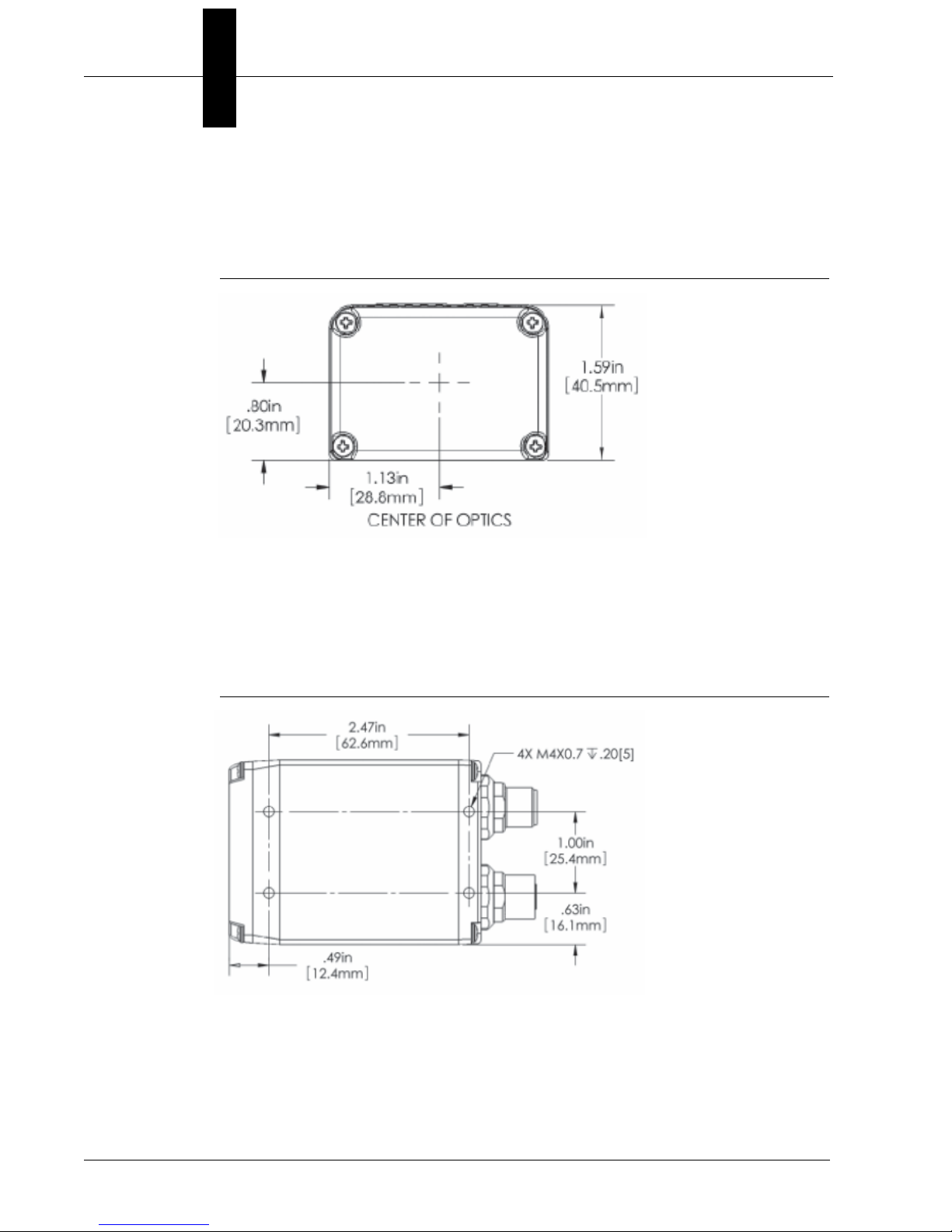
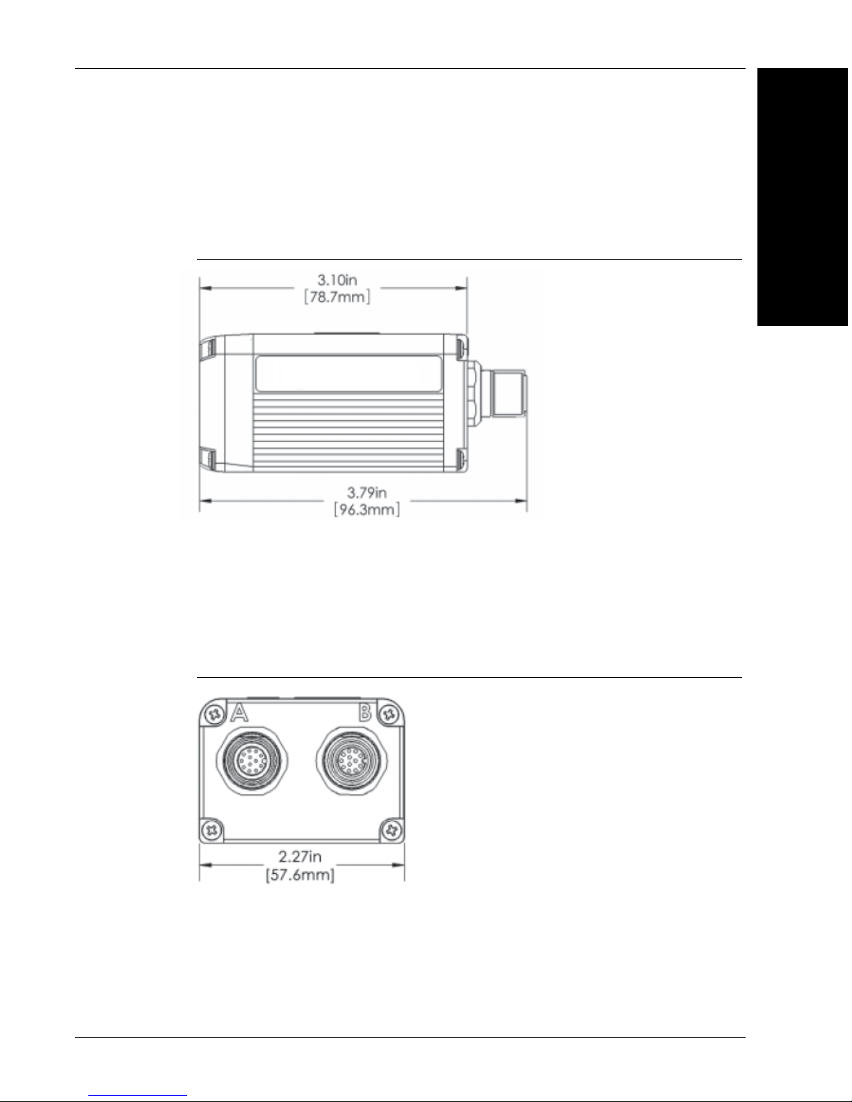
Dimensions
Note:
Nominal dimensions shown. Typical tolerances apply.
FIGURE C–1. Vision HAWK Smart Camera Dimensions
Dimensions
C
General
Specifications
Vision HAWK Smart Camera Guide C-7
Page 76

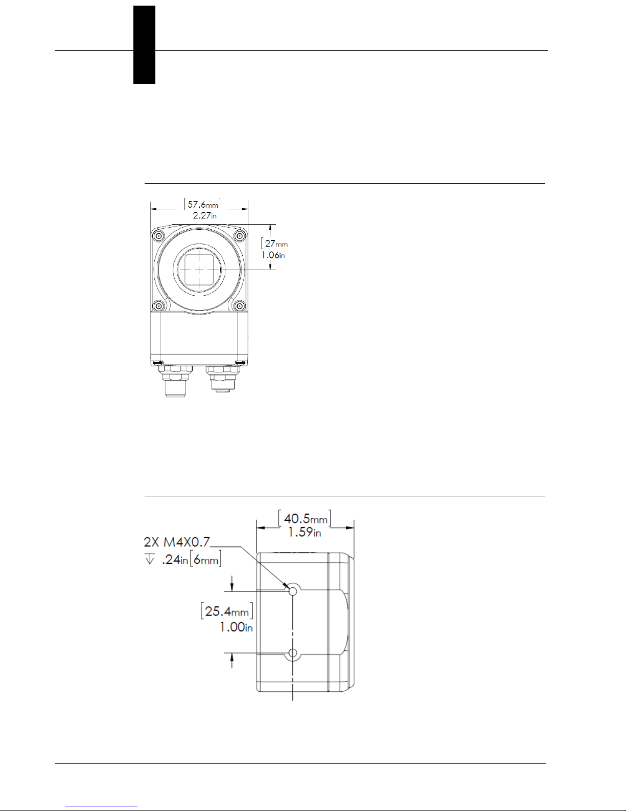
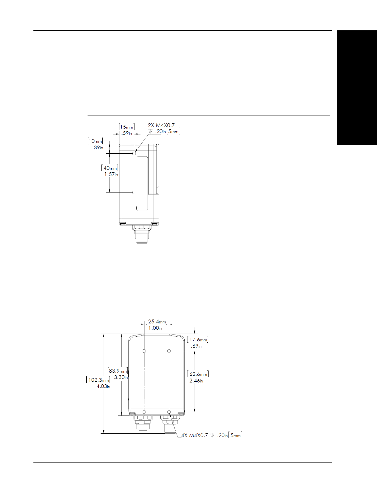
Appendix C General Specifications
Note: Nominal dimensions shown. Typical tolerances apply.
Note: C-Mount lens
protection housing has
a thread of M48 x 1.5.
FIGURE C–2. Vision HAWK C-Mount Smart Camera Dimensions
C-8 Vision HAWK Smart Camera Guide
Page 77

Field of View and Working Distance
Field of View and Working Distance
C
General
Specifications
Vision HAWK Smart Camera Guide C-9
Page 78

Appendix C General Specifications
C-10 Vision HAWK Smart Camera Guide
Page 79

D
APPENDIX D CloudLink Web HMI
CloudLink allows you to visualize Microscan Link values and images
from compatible Microscan smart cameras and vision systems. It runs in
your web browser, and is compatible with a wide variety of modern
browsers including those found on tablets and smart phones.
This appendix contains information about CloudLink support for the Vision
HAWK. Refer to Getting Started with CloudLink – installed in the
documentation folder C:\Microscan\Vscape\Documentation during
AutoVISION/Visionscape installation – for detailed information about
configuring and using the CloudLink web HMI.
D
CloudLink Web HMI
CloudLink requires an HTML5-compatible browser.
• Internet Explorer 10 or later
• Google Chrome
• Firefox
• Mobile Safari (iPhone / iPad)
• Mobile Chrome on Android devices
The following browswers were explicitly tested for compatibility:
• Internet Explorer 10.0.9
• Internet Explorer 11.0.2
• Google Chrome 33.0
• Firefox 28.0
Additional Notes:
• Windows Safari is not supported.
• Internet Explorer 11 or later and Google Chrome 33 or later are
recommended for extended CloudLink sessions.
Vision HAWK Smart Camera Guide D-1
Page 80

Appendix D CloudLink Web HMI
Click the CloudLink Dashboard
icon to launch the application.
Connecting
To launch CloudLink, use your favorite web browser and enter the address of your device
in the browser’s address bar. For example, if you have a Microscan smart camera on your
network at address 10.20.1.123, you would enter:
CloudLink also works with Visionscape Software and with AutoVISION’s Emulator.
To connect to a software-based job running in FrontRunner or AutoVISION:
First, be sure the job is running, and then type the following into your browser’s address bar:
Note: You must specify port 8080 for a PC-based connection. If you are connecting to a
PC-based system from a different machine on the network, use the IP address of the PC
instead of the local host. For example, use http://10.20.1.234:8080 if the PC’s IP address
is 10.20.1.234.
Once you press the Enter key, you should see the following home page:
D-2 Vision HAWK Smart Camera Guide
Page 81

Application Overview
Application Overview
The CloudLink Dashboard user interface is a single page web app-style application. Most
web pages show information that can typically extend beyond the bottom of the browser
window, requiring the user to scroll to see it. They typically contain links to other pages,
which is how the user navigates around a web site.
In contrast, CloudLink behaves more like an application, expanding to fill the browser
window, and automatically adapting to any changes in the dimensions of the window.
Although CloudLink allows you to define and use multiple display pages, they are all
contained within a single web page.
The browser stores a maximum of 50 images. The camera stores images, image
thumbnails, and data records that can be requested via the web page or API. When
memory is full, the camera will first delete full-size images, then thumbnails, and ultimately
the data records on a first in-first out basis.
This is a typical view of a CloudLink page.
D
CloudLink Web HMI
Note: CloudLink does not currently support display of color images from color cameras.
Vision HAWK Smart Camera Guide D-3
Page 82

Appendix D CloudLink Web HMI
Application Bar
The Application Bar is located at the top of the CloudLink interface.
There are three components to the Appplication Bar:
• A set of page selection buttons. In the example above they appear as tabs, but the
style can be customized if necessary.
• A logo. The position and contents of the logo can be customized.
• A toolbar. The toolbar provides access to various CloudLink settings and modes. The
position and size of the toolbar can be customized.
D-4 Vision HAWK Smart Camera Guide
Page 83

Pages, Panels, and Widgets
Pages, Panels, and Widgets
The main area of CloudLink displays one of a number of pages. If there is more than one
page defined, you can switch between them by using the page selection buttons on the
application bar, or by using the arrow keys on your keyboard.
Each page is organized into a set of regions called panels. The following image shows an
empty page to demonstrate the arrangement of the panels on a page.
D
CloudLink Web HMI
Note the names, which start with .panel-. It is not necessary to know these names to use
CloudLink; however they do have significance if there should be need for customization.
Customizing CloudLink requires the modification of CSS (Cascading Style Sheets). The
names shown correspond to the CSS class selector for that panel.
The purpose of the panels is to act as containers for a number of widgets. Each widget
has the ability to visualize and interact with one or more items of inspection data such as
Microscan Link values, inspection counters, timing information, or images.
Vision HAWK Smart Camera Guide D-5
Page 84

Appendix D CloudLink Web HMI
Each panel has special layout and behavior properties that can be exploited to create a
wide variety of different layouts. The following table summarizes the position and
properties of each panel:
D-6 Vision HAWK Smart Camera Guide
Page 85

Pages, Panels, and Widgets
If a panel does not have content (i.e. no widgets are placed in it), it is hidden from view, with
the other panels adjusted to occupy the available space. Examples of possible page layouts:
D
CloudLink Web HMI
Vision HAWK Smart Camera Guide D-7
Page 86

Appendix D CloudLink Web HMI
D-8 Vision HAWK Smart Camera Guide
Page 87

E
APPENDIX E Serial Commands
This section provides descriptions of the serial commands that can be
sent to the camera via TCP (Telnet) port, AutoVISION Terminal, or
HyperTerminal.
E
Serial Commands
Vision HAWK Smart Camera Guide E-1
Page 88

Appendix E Serial Commands
Serial Command Syntax
< > = Required argument. Replace appropriately.
For example:
-u <DB_User_name> becomes -u av where av replaces
DB_User_name.
| = Mutually exclusive arguments. Choose one from the list.
{ } = Used with | to specify a list of choices for an argument.
[ ] = Optional parameter.
Important: Unless otherwise stated, commands will respond with !OK on
success and !ERROR on failure.
GETIMAGE <-transfer=ymodem> [-format={jpg|png}] [-quality
={0-100}] [-woi=left,top,right,bottom] [-inspection=n]
Initiates serial transfer of inspection image (RS-232 only).
Note: This command always returns the last (most recent) image.
-transfer=ymodem is currentlynot optional - only Ymodem protocol is
supported.
-format={jpg|png} specifies the format of the image. If omitted, the
image format is JPG.
-quality=n specifies a JPG compression quality of n less than or equal to
100. The default quality is 80 if not specified.
Note: The PNG format provides lossless image comp ression. If format is
set to PNG, the quality setting does not apply.
woi=left,top,right,bottom specifies a rectangular area of the image to be
included in the output image. If omitted, the full image buffer is returned.
-inspection=n specifies the inspection from which to retrieve an image.
The image will be from the first snapshot within that inspection. If not
specified, the image will be from the first inspection that does contain a
snapshot.
The following example will retrieve an image from the camera with these
settings: Protocol: ymodem; Format: png; Quality: N/A; Inspection:
second inspection.
GETIMAGE –transfer=ymodem –format=png –inspection=2
The following example will retrieve an image from the camera with these
settings: Protocol: ymodem; Format: jpg (default); Quality: 50;
Inspection: first inspection (default).
GETIMAGE –transfer=ymodem –quality=50
E-2 Vision HAWK Smart Camera Guide
Page 89

ONLINE
Starts all inspections.
OFFLINE
E
Stops all inspections.
TRIGGER
Triggers an inspection.
vt [n]
Triggers an inspection by pulsing a Virtual I/O point.
For example:
vt 1
will return pulse VIO1. The inspection will run if it is configured to use VIO
1 as a trigger.
If specified, the VIO index must be in the allowed range for Virtual I/O
points within Visionscape. The virtual I/O line will be set high then low.
If VIO Index is not specified, VIO1 is assumed.
Serial Commands
Fail Return: Return !ERROR followed by the reason for the failure.
For example:
!ERROR No such trigger
when the index specified ‘n’ is out of range of virtual triggers.
REBOOT [-noload]
Reboots the device.
-noload = do not load BOOT job.
Vision HAWK Smart Camera Guide E-3
Page 90

Appendix E Serial Commands
MEMAVAIL [-cp]
Returns available memory for device or coprocessor.
MEMCONTIG [-cp]
Returns maximum memory block for device or coprocessor.
MEMFRAGS [-cp]
Returns memory fragments for device or coprocessor.
MEMINFO [-cp] [-v]
Returns memory summary “avail/contig/frags” for device or coprocessor.
Verbose.
VERSION
Returns Visionscape software version.
JOBSAVE [-slot=]<n>
Saves current job to slot n.
JOBLOAD [-slot=]<n> [-r]
Loads job from slot n.
-r = Start inspections.
JOBDELETE {[-slot=]n|-all}
Deletes job in slot n, or all jobs if -all.
Important: Does not delete the current job loaded in camera memory.
E-4 Vision HAWK Smart Camera Guide
Page 91

JOBINFO [[-slot=]n] [-v]
Gets job summary or info about slot n.
JOBINFO with no arguments returns a list of all jobs on the device.
-v = Ve rbose n. This option shows the amount of space that would be
freed if the job were deleted. It also lists the total disk space and free disk
space.
JOBBOOT [-slot=]<n>
Sets bootup job slot n (RS-232 only).
JOBDOWNLOAD <-transfer=ymodem>
Downloads .avz job packaged via transfer method (RS-232 only).
E
Serial Commands
SET <tagname> <value>
Sets value of a global tag.
The tagname must correspond to one of the supported tags within the
device.
The value can contain spaces.
The command is terminated by a carriage return and/or line feed
character.
The value can be a list of comma-separated items to set a sequence of tags:
Send SET int1 1, 2, 3 to set int1 = 1, int2 = 2, int3 = 3.
The AVP service allows setting of step and datum information from the job
tree using forward
avp/insp1/snapshot1/acq1/gain 2.0 paths are not case -sensitive and do
not need to be fully qualified if unique.
SET avp/acq1/gain 2.0 will set the same gain value if there is only one
acquire.
slash ‘/’ in the symbolic name path. SET
Vision HAWK Smart Camera Guide E-5
Page 92

Appendix E Serial Commands
Control tags in the A VP service such as START, STOP, a nd TRIGGER act
as momentary switches. SET avp.start 1 is equivalent to the ONLINE
command. avp.start will reset immediately and always read as 0.
Success Return: On success will return !OK followed by an echo of the
command.
For example:
!OK SET matchstring1
Fail Return: On failure will return !ERROR followed by the reason for the
failure.
For example:
!ERROR Tag matchstring66 not found
GET {tagname|service|service.tagname}
Gets value of a global tag.
The tagname must correspond to one of the supported tags within the
device.
The command is terminated by a carriage return and/or line feed
character.
Include an index to get a single value from an array such as GET int1. If
the index is omitted, the full array of values will be returned in a commaseparated list of values.
Send Get {tagname|service.tagname|service} to get the value of a tag
within the global data service. To get the value of a tag within another
service, prefix the tagname with the service name. For example, a GET
<service.tagname> command such as GET eip.input for the EIP input
assembly.
The AVP service allows retrieval of step and datum information from the
job tree using forward slash ‘/’ in the symbolic name path. GET
avp/insp1/snapshot1/status paths are not case-sensitive and do not
need to be fully qualified if unique.
E-6 Vision HAWK Smart Camera Guide
Page 93

GET avp/snapshot1 /st atus will return the same result if there is only one
inspection.
When issued against a step, GET avp/snapshot1 will return the values
for all datums.
Success Return: On success will return the value stored in the tag.
For example:
ABCD
Fail Return: On failure will return !ERROR followed by the reason for the
failure.
For example:
!ERROR Tag matchstring66 not found
E
Serial Commands
INFO [tagname|service]
Gets information about a tag or service.
INFO with no arguments gets a list of services.
INFO <service> gets a list of tags in that service.
INFO <service.tagname> gets attributes of the tag as well as a list of
subtags.
The AVP service allows retrieval of step and datum information from the
job tree using forward slash ‘/’ in the symbolic name path. INFO
avp/insp1/snapshot1/status paths are not case-sensitive and do not
need to be fully qualified if unique.
INFO avp/snapshot1/status will return the same result if there is only
one inspection.
When issued against a step, INFO avp/snapshot1 returns properties of
the step, a list of child datums, and a list of child steps. Child steps are
indicated by a trailing forward slash.
Vision HAWK Smart Camera Guide E-7
Page 94

Appendix E Serial Commands
QUERYAUTOCAL
Returns photometry settings: Gain, Exposure, and Focus.
AUTOCAL
Performs automatic calibration of photometry settings: Gain, Exposure,
and Focus.
TARGET {0|1|off|on}
Turns targeting LEDs On or Off.
CHECKSUM {BOOT | KERNEL | BOOTPARAM}
HELP
Gets a checksum on an individual part of the system.
Returns a list of all serial commands showing correct syntax and
functionality descriptions.
E-8 Vision HAWK Smart Camera Guide
Page 95

F
APPENDIX F Vision HAWK Boot Modes
This section describes the Vision HAWK’s Diagnostic Boot Mode and
Boot Error Mode.
F
Modes
Vision HAWK Boot
Vision HAWK Smart Camera Guide F-1
Page 96

Appendix F Vision HAWK Boot Modes
Diagnostic Boot Mode
The Vision HAWK supports a special boot mode used for diagnostics and
recovery. There are two ways in which the camera can be put into this mode:
1. This method requires an Ethernet connection between the host PC
and Vision HAWK. Power-on the unit and hold the AutoVISION button
down until the green flash illuminates once. For C-Mount versions,
hold the button down for approximately 30 seconds. The unit is now
configured for IP address 192.168.0.10 with subnet mask
255.255.255.0. Establish a telnet connection between the host PC
and Vision HAWK. The [SAFE-KERNEL] prompt is displayed.
2. This method requires a QX-1 and a serial connection between the
host PC running a terminal emulator and Vision HAWK camera.
Power-on the unit and hold down the Tab key down for several
seconds. The unit will boot to a [SAFE-KERNEL] prompt with
communication settings of 115200, N, 8, 1 (baud, parity, data bits,
stop bits).
Once the unit is booted, there are many possible actions the user can
take. However, the most useful actions are listed below.
In rare situations, the boot job executed at camera startup can cause
unexpected behavior. If this is the suspected case, it is possible to disable
loading and running of the boot job at startup using the following
command.
[SAFE-KERNEL] BP_UpdateStartupOptions(0, 0)
Note that the loading and running of the boot job is automatically re-enabled
the next time a job is saved to camera flash from AutoVISION or
FrontRunner.
At boot time, the system configures itself using a set of information known
as boot parameters. To obtain a list of the current configuration’s boot
parameters, issue the following command:
[SAFE-KERNEL] BP_Dump()
F-2 Vision HAWK Smart Camera Guide
Page 97

Should your device need to be configured with different IP information, follow the example
below and substitute the appropriate settings for IP address, subnet mask, and gateway
address, respectively.
F
[SAFE-KERNEL] BP_UpdateIP(“192.168.0.10”, “255.255.255.0”, “192.168.0.100”)
It is possible to configure the system to acquire its IP address via DHCP or to use a static
IP address. Issue the following command with a ‘0’ for static IP or a ‘1’ for DHCP.
[SAFE-KERNEL] BP_UpdateDHCP(0)
Boot Error Mode
The Vision HAWK enters an error mode on boot if it’s unable to fully load Visionscape.
This mode is visually displayed to the user by flashing the Error LED along with the
OUTPUT 1, OUTPUT 2, and OUTPUT 3 LEDs on the front of the unit. Additionally, this
mode is represented as a “BOOT_ERR” in the Network Overview tool.
Modes
Vision HAWK Boot
If you encounter this error condition, you will need to reload the firmware using the Smart
Camera Firmware Update Tool.
Vision HAWK Smart Camera Guide F-3
Page 98

Appendix F Vision HAWK Boot Modes
F-4 Vision HAWK Smart Camera Guide
 Loading...