

Page 1

QX Hawk Industrial Imager
User’s Manual
P/N 83-006800 Rev A
Page 2

Copyright and Disclaimer
Copyright ©2010
by Microscan Systems, Inc.
ISO 9001 Certified
Issued by TüV USA
All rights reserved. The information contained herein is proprietary and is provided solely for the purpose
of allowing customers to operate and/or service Microscan manufactured equipment and is not to be
released, reproduced, or used for any other purpose without written permission of Microscan.
Throughout this manual, trademarked names might be used. Rather than place a trademark (™) symbol
at every occurrence of a trademarked name, we state herein that we are using the names only in an editorial
fashion, and to the benefit of the trademark owner, with no intention of infringement.
Disclaimer
The information and specifications described in this manual are subject to change without notice.
Latest Manual Version
For the latest version of this manual, see the Download Center on our web site at:
www.microscan.com.
Technical Support
For technical support, e-mail: helpdesk@microscan.com.
Warranty and Terms of Sale
For Standard Warranty information, see: www.microscan.com/warranty.
Microscan Systems, Inc.
Renton Headquarters
Tel: 425.226.5700 / 800.251.7711
Fax: 425.226.8250
Nashua Office
Tel: 603.598.8400
Fax: 603.577.5818
Microscan Europe
Tel: 011 31 172 423360
Fax: 011 31 172 423366
Microscan Asia Pacific
Tel: 65 6846 1214
Fax: 65 6846 4641
ii QX Hawk Industrial Imager User’s Manual
Page 3

Table of Contents
Chapter 1 Quick Start
Step 1 Check Hardware ..........................................................................1-2
Step 2 Connect the System.....................................................................1-3
Step 3 Position the Imager ......................................................................1-4
Step 4 Install ESP....................................................................................1-5
Step 5 Select Model ................................................................................ 1-6
Step 6 Connect........................................................................................1-7
Step 7 Locate Symbol .............................................................................1-9
Step 8 Calibrate.....................................................................................1-11
Step 9 Test Read Rate ..........................................................................1-12
Step 10 Configure the Imager ...............................................................1-13
Step 11 Save Changes.......................................................................... 1-14
Chapter 2 Using ESP
EZ Mode .................................................................................................. 2-2
App Mode ................................................................................................ 2-3
Menu Toolbar .......................................................................................... 2-4
Navigating in ESP................................................................................. 2-15
Send/Receive Options.......................................................................... 2-16
Introduction
Chapter 3 Hardware Integration
Connectors .............................................................................................. 3-2
Cordsets ..................................................................................................3-3
QX Hawk and QX-1 Connectors and Pinouts..........................................3-4
Power and Trigger Switching...................................................................3-6
Port Routing.............................................................................................3-7
Application Examples ..............................................................................3-8
Chapter 4 Setup
Video .......................................................................................................4-2
Evaluation............................................................................................. 4-11
Calibration ............................................................................................. 4-14
Window of Interest .................................................................................4-15
Configuration Database......................................................................... 4-17
Ordered Output......................................................................................4-24
Output Format ....................................................................................... 4-28
Dynamic Setup ...................................................................................... 4-32
Chapter 5 Parameters
Communication........................................................................................ 5-2
Read Cycle ............................................................................................ 5-40
Symbologies ..........................................................................................5-61
I/O Parameters ......................................................................................5-93
Symbol Quality .................................................................................... 5-155
Matchcode ...........................................................................................5-162
QX Hawk Industrial Imager User’s Manual iii
Page 4

Table of Contents
Diagnostics.......................................................................................... 5-171
Chapter 6 Terminal
Terminal Window..................................................................................... 6-2
Find ......................................................................................................... 6-3
Send ........................................................................................................ 6-4
Macros..................................................................................................... 6-5
Terminal Window Menus......................................................................... 6-6
Chapter 7 Utilities
Serial Utility Commands .......................................................................... 7-2
Read Rate ............................................................................................... 7-4
Counters.................................................................................................. 7-6
Device Control......................................................................................... 7-9
Differences from Default........................................................................ 7-10
Master Database ................................................................................... 7-11
Firmware ............................................................................................... 7-17
Bar Code Configuration Mode............................................................... 7-21
Calibration ............................................................................................. 7-22
Default/Reset/Save ............................................................................... 7-23
Imager Status ........................................................................................ 7-25
Learn Operations................................................................................... 7-27
Reboot System...................................................................................... 7-28
Static Validation..................................................................................... 7-29
Targeting ............................................................................................... 7-31
Temperature.......................................................................................... 7-32
Y-Modem Transfer Options ................................................................... 7-33
Appendices
Appendix A General Specifications .........................................................A-2
Appendix B Electrical Specifications .......................................................A-7
Appendix C Ground and Shield Considerations......................................A-9
Appendix D Flying Lead Cordset Pinouts..............................................A-11
Appendix E Serial Commands ..............................................................A-12
Appendix F Protocol Commands...........................................................A-66
Appendix G ASCII Table .......................................................................A-75
Appendix H Configuring Ethernet TCP/IP .............................................A-76
Appendix I Interface Standards .............................................................A-79
Appendix J Glossary of Terms ..............................................................A-80
iv QX Hawk Industrial Imager User’s Manual
Page 5

Introduction
About the QX Hawk Industrial Imager
The key features of the QX Hawk Industrial Imager are:
• Fully integrated liquid lens technology, allowing infinite focus flexibility
• High-resolution modular optical zoom system
• Simple plug-and-play connectivity with Ultra-Lock™ cordsets and connectors
• Best-in-class X-Mode™ algorithms
• Embedded Ethernet TCP/IP
• A green flash (visible from all angles) to signal a successful read
• LED array for performance, communication, and I/O user feedback
• EZ Button for setup and testing
• Compact size for easy integration into a wide variety of applications
• IP65/67 enclosure
Imager Communication
There are three ways to configure and test the QX Hawk:
• Microscan’s Windows-based ESP Software (Easy Setup Program), which offers
point-and-click ease of use and visual responses to user adjustments.
• Serial commands, such as <K100,1>, that can be sent from ESP’s Termina l or another
terminal program.
•The EZ Button on the top of the imager.
“Ultra-Lock” is a trademark of Woodhead (Molex).
QX Hawk Industrial Imager User’s Manual v
Page 6

Warning and Caution Summary
Warning and Caution Summary
This equipment has been tested and found to comply with the limits for a Class A digital
device, pursuant to part 15 of the FCC Rules. These limits are designed to provide reasonable
protection against harmful interference in a residential installation. This equipment generates,
uses, and can radiate radio frequency energy, and, if not installed and used in accordance
with the instructions, may cause harmful interference to radio communication. However,
there is no guarantee that interference will not occur in a particular installation. If this
equipment does cause harmful interference to radio or television reception, which can be
determined by turning the equipment off and on, the user is encouraged to try to correct
the interference by one or more of the following measures:
• Reorient or relocate the receiving antenna;
• Increase the separation between the equipment and receiver;
• Connect the equipment into an outlet on a circuit different from that to which the receiver
is connected;
• Consult the dealer or an experienced radio/TV technician for help.
For connection to a UL-listed direct plug-in power unit marked Class II and rated 10 to 28
VDC at 5 watts or greater.
European models must use a similarly rated Class I or Class II power supply that is certified
to comply with standard for safety EN 60950.
Use of controls, adjustments, or performance of procedures other than those specified
herein may result in hazardous LED light radiation exposure.
There are no user-serviceable parts in the imager. Opening the imager voids the Microscan
Systems, Inc. warranty.
vi QX Hawk Industrial Imager User’s Manual
Page 7

Introduction
Statement of Agency Compliance
The QX Hawk has been tested for compliance with FCC (Federal Communications
Commission) regulations and has been found to conform to all applicable FCC Rules
and Regulations.
To comply with FCC RF exposure compliance requirements, this device must not be co-located
or operate in conjunction with any other antenna or transmitter.
Changes or modifications not expressly approved by the party responsible for compliance
could void the user’s authority to operate the equipment.
The QX Hawk has been tested for compliance with CE (Conformité Européenne) standards
and guidelines, and has been found to conform to applicable CE standards, specifically
the following requirements:
General Immunity for Light Industry: EN 55024:1998 ITE Immunity Standard
Radiated and Conducted Emissions of ITE Equipment: EN 55022:98 ITE Disturbances
The QX Hawk has been tested by an independent electromagnetic compatibility laboratory
in accordance with the applicable specifications and instructions.
QX Hawk Industrial Imager User’s Manual vii
Page 8

Statement of RoHS Compliance
Statement of RoHS Compliance
All Microscan readers with a ‘G’ suffix in the FIS number are RoHS-Compliant. All compliant
readers were converted prior to March 1, 2007. All standard accessories in the Microscan
Product Pricing Catalog are RoHS-Compliant except 20-500013-01 and 98-000039-02.
These products meet all the requirements of the European Parliament and the Council of
the European Union for RoHS compliance. In accordance with the latest requirements, our
RoHS-compliant products and packaging do not contain intentionally added Deca-BDE,
Perfluorooctanes (PFOS) or Perfluorooctanoic Acid (PFOA) compounds above the maximum
trace levels. To view the documents stating these requirements, please visit:
http://eur-lex.europa.eu/LexUriServ/LexUriServ.do?uri=CELEX:32002L0095:EN:HTML
and
http://eur-lex.europa.eu/LexUriServ/LexUriServ.do?uri=OJ:L:2006:372:0032:0034:EN:PDF
Please contact your sales manager for a complete list of Microscan’s RoHS-Compliant products.
This declaration is based upon information obtained from sources which Microscan believes to be reliable, and
from random sample testing; however, the information is provided without any representation of warranty,
expressed or implied, regarding accuracy or correctness. Microscan does not specifically run any analysis on our
raw materials or end product to measure for these substances.
The information provided in this certification notice is correct to the best of Microscan’s knowledge at the date of
publication. This notice is not to be considered a warranty or quality specification. Users are responsible for
determining the applicability of any RoHS legislation or regulations based on their individual use of the product.
viii QX Hawk Industrial Imager User’s Manual
Page 9

Contents
Step 1 Check Hardware................................................................................................................1-2
Step 2 Connect the System ..........................................................................................................1-3
Step 3 Position the Imager............................................................................................................ 1-4
Step 4 Install ESP.........................................................................................................................1-5
Step 5 Select Model......................................................................................................................1-6
Step 6 Connect ............................................................................................................................. 1-7
Step 7 Locate Symbol.................................................................................................................. 1-9
Step 8 Calibrate ..........................................................................................................................1-11
Step 9 Test Read Rate ...............................................................................................................1-12
Step 10 Configure the Imager.................................................................................................... 1-13
Step 11 Save Changes.............................................................................................................. 1-14
1 Quick Start
This section explains how to set up and test the QX Hawk quickly using
Detailed setup information for installing the imager into an application can be found in
subsequent sections.
QX Hawk Industrial Imager User’s Manual 1-1
ESP
(Easy Setup Program).
Page 10
Check Hardware
Hardware Required
Caution: Be sure that all connections are secure BEFORE applying power to
the system. Always power down BEFORE disconnecting any cables.
Serial Standalone (with QX-1)
Ethernet Standalone (with QX-1)
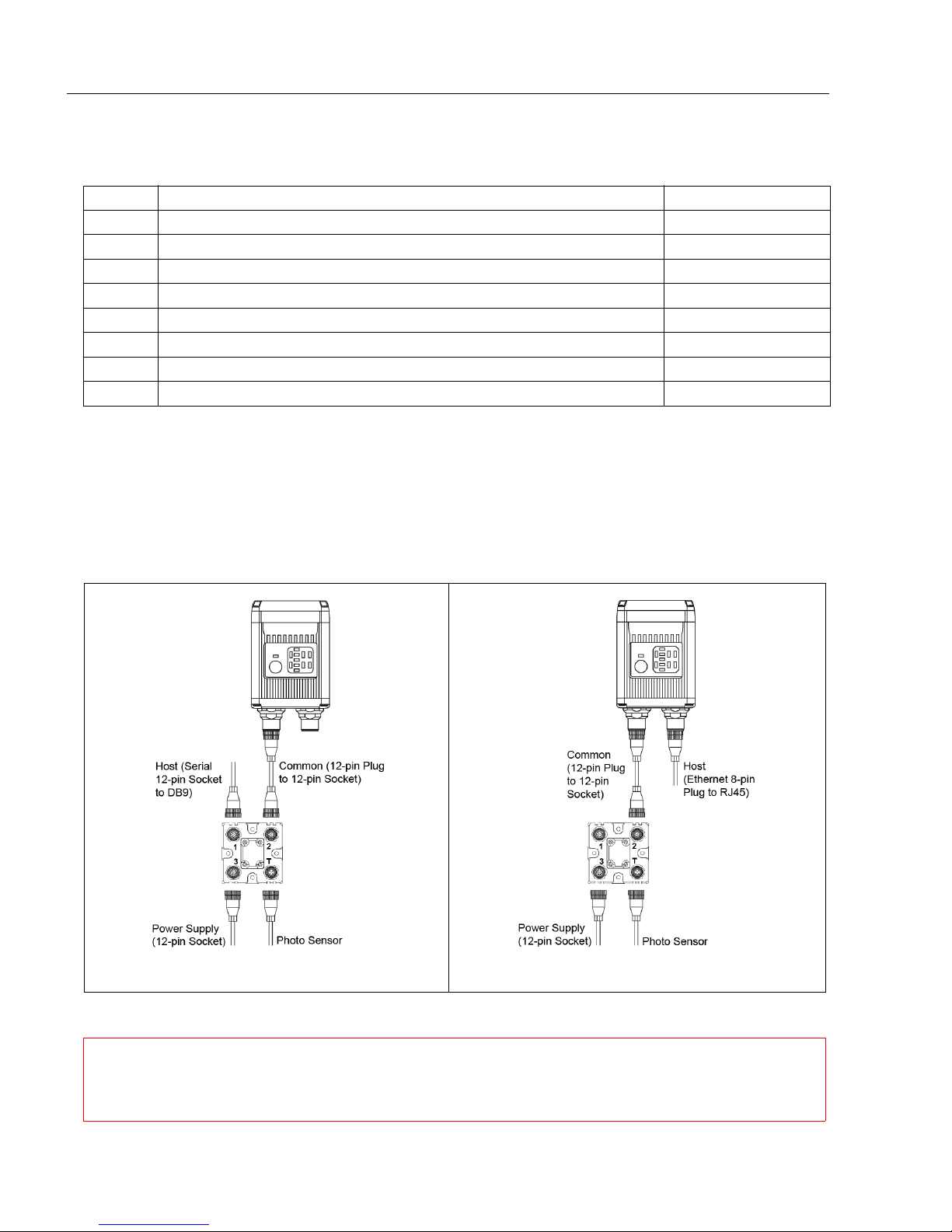
Step 1 — Check Hardware
Item Description Part Number
1 QX Hawk Industrial Imager FIS-6800-XXXXG
2 QX-1 Interface Device 98-000103-01
QX Cordset, Common, M12 12-pin Plug to M12 12-pin Socket, 1 m
3
4 QX Cordset, Host, Serial, M12 12-pin Plug to DB9, 1 m 61-000152-01
5 QX Cordset, Host, Serial, M12 12-pin Socket to DB9, 1 m 61-000153-01
6 QX Power Supply, M12 12-pin Socket, 1.3 m 97-000003-01
7 QX Cordset, Host, Ethernet, M12 8-pin Plug to RJ45, 1 m 61-000160-01
8 QX Photo Sensor, M12 4-pin Plug, NPN, Dark On, 2 m 99-000020-02
Note:
Additional cordsets and accessories are available in the Microscan Product Pricing Catalog.
Note: The QX Hawk does not require an Ethernet crossover cordset, because the imager
itself performs automatic internal crossover (transmit-to-receive switching). Microscan
offers a standard straight-through (un-crossed) Ethernet cordset (61-000160-01).
Important: Do not attempt to power more than four imagers with a single power supply in
a daisy chain configuration. Add a QX-1 and one power supply for every four additional
imagers in the daisy chain.
61-000162-01
1-2 QX Hawk Industrial Imager User’s Manual
Page 11
Quick Start
Serial Standalone (with QX-1) Ethernet Standalone (with QX-1)
Step 2 — Connect the System
Important: When connecting Ultra-Lock cordsets to the QX Hawk and QX-1, align the
pins first and then push the connector into place. Do not twist
bend the pins.
Important: Do not attempt to power more than four imagers with a single power supply in
a daisy chain configuration. Add a QX-1 and one power supply for every four additional
imagers in the daisy chain.
RS-232
• Connect the Serial Communication Cable from “A” on the QX Hawk to “2” on the QX-1.
• Connect the host cable from “1” on the QX-1 to the host computer.
• Connect the photo sensor to “T” on the QX-1.
• Connect the power supply to “3” on the QX-1.
• Plug in the power supply.
Ethernet
Note: The QX Hawk does not require an Ethernet crossover cordset, because the imager
itself performs automatic internal crossover (transmit-to-receive switching). Microscan
offers a standard straight-through (un-crossed) Ethernet cordset (61-000160-01).
• Connect the Ethernet Cable from “B” on the QX Hawk to the network.
• Connect the photo sensor to “T” on the QX-1.
• Connect the power supply to “A” on the QX Hawk.
• Plug in the power supply.
the connectors, as this will
QX Hawk Industrial Imager User’s Manual 1-3
Page 12
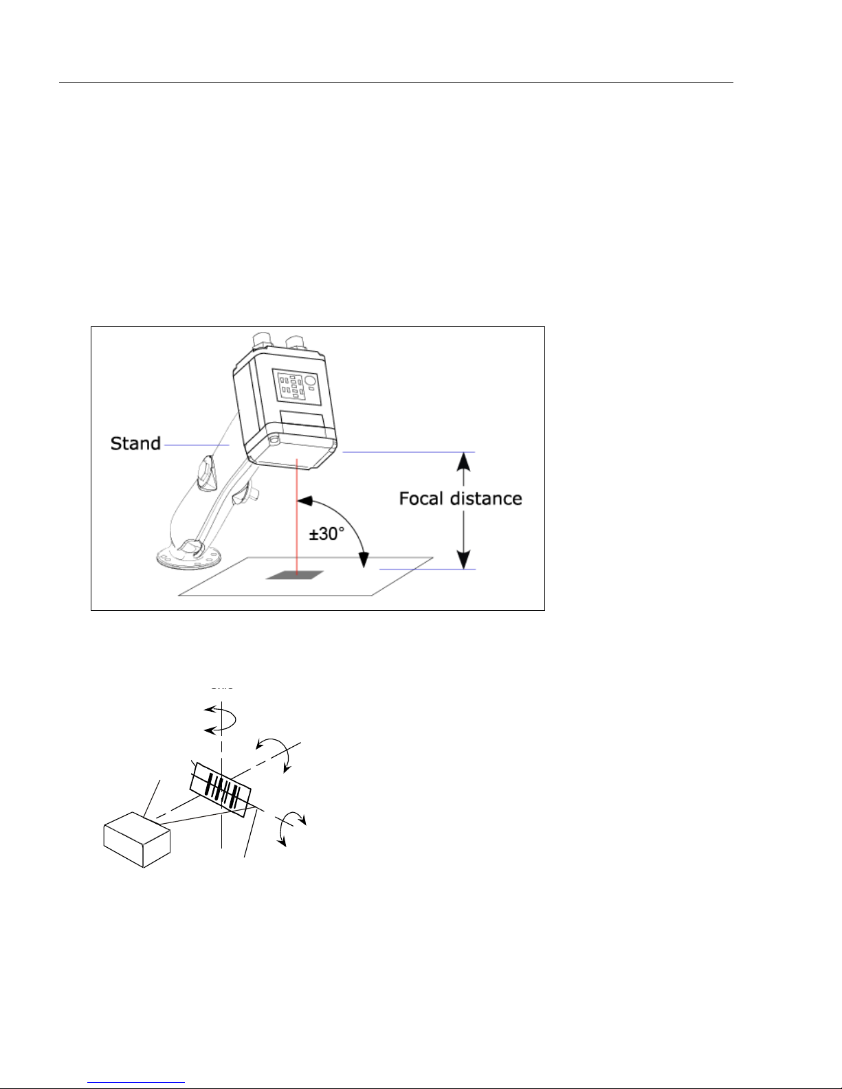
Position the Imager
Imager and Symbol Orientation
Pitch
axis
Bar code
label
Tilt
axis
axis
Scan line
Scanner
Pitch
Tilt
Skew
Symbol
Imager
Maximum skew,
tilt,
and pitch:
±30°
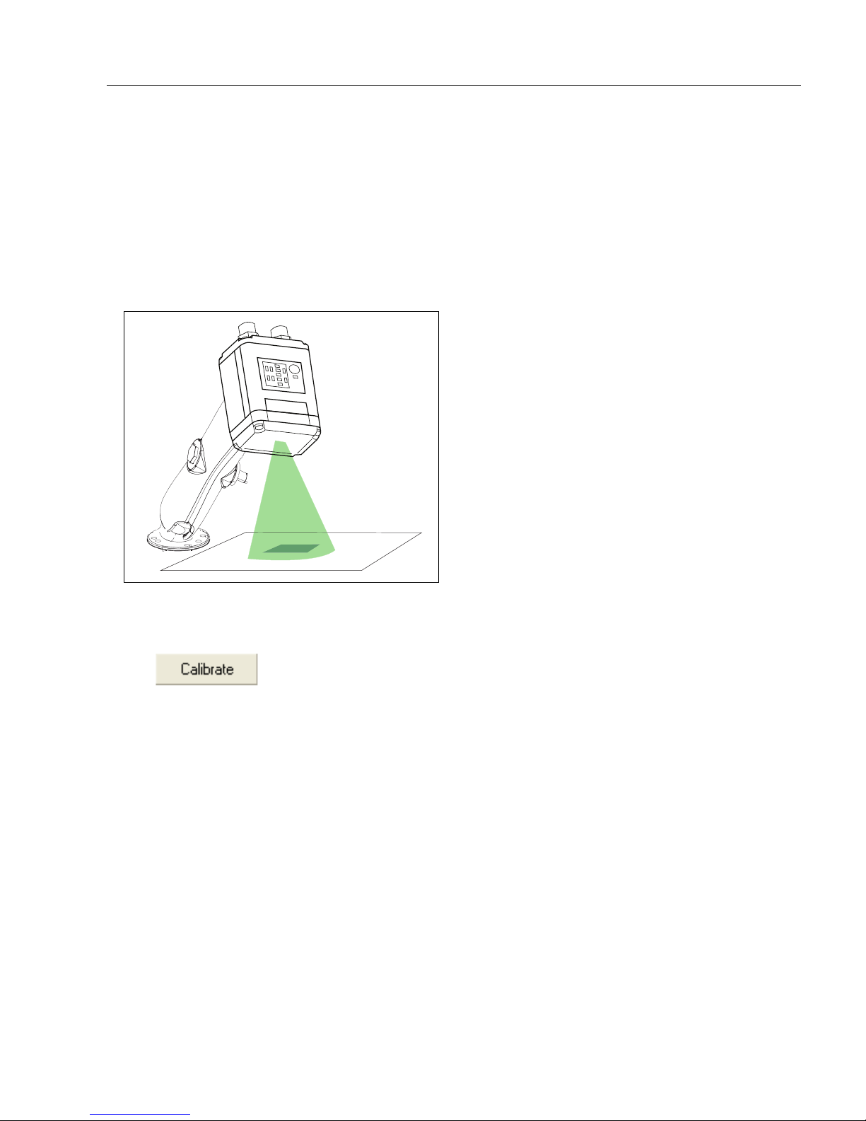
Step 3 — Position the Imager
• Position the imager at a focal distance of one inch or more from a test symbol.
• Tip the imager relative to the symbol to avoid the glare of direct (specular) reflection.
The case parting line should be perpendicular to the plane of the symbol by either pitching
the symbol or the imager as shown.
• Symbols can be rotated (tilted) at any angle; however, for best results symbols should
be aligned with the field of view. In the case of linear symbols, aligning the bars in the
direction of their movement (ladder orientation) will minimize the chances of blurring and
will result in more consistent decodes.
Important: Avoid excessive skew or pitch. Maximum skew is ±30°; maximum pitch is
±30°. The illustration below shows skew axis, pitch axis, and tilt axis.
1-4 QX Hawk Industrial Imager User’s Manual
Page 13

Quick Start
Step 4 — Install ESP
ESP Software can be found on the Microscan Tools CD that is packaged with the QX Hawk.
1. Follow the prompts to install ESP from the CD.
2. Click on the ESP icon to run the program.
Note: ESP can also be installed from the Download Center at www.microscan.com.
Minimum System Requirements
• 166 MHz Pentium processor (Pentium II processor recommended)
• Windows Vista, XP, or 2000 operating system
• Internet Explorer 5.0 or higher
• 64 MB minimum RAM (128+ MB RAM recommended)
• 80 MB hard drive space
• 800 x 600 minimum 256 color display (1024 x 768 32-bit color recommended)
QX Hawk Industrial Imager User’s Manual 1-5
Page 14
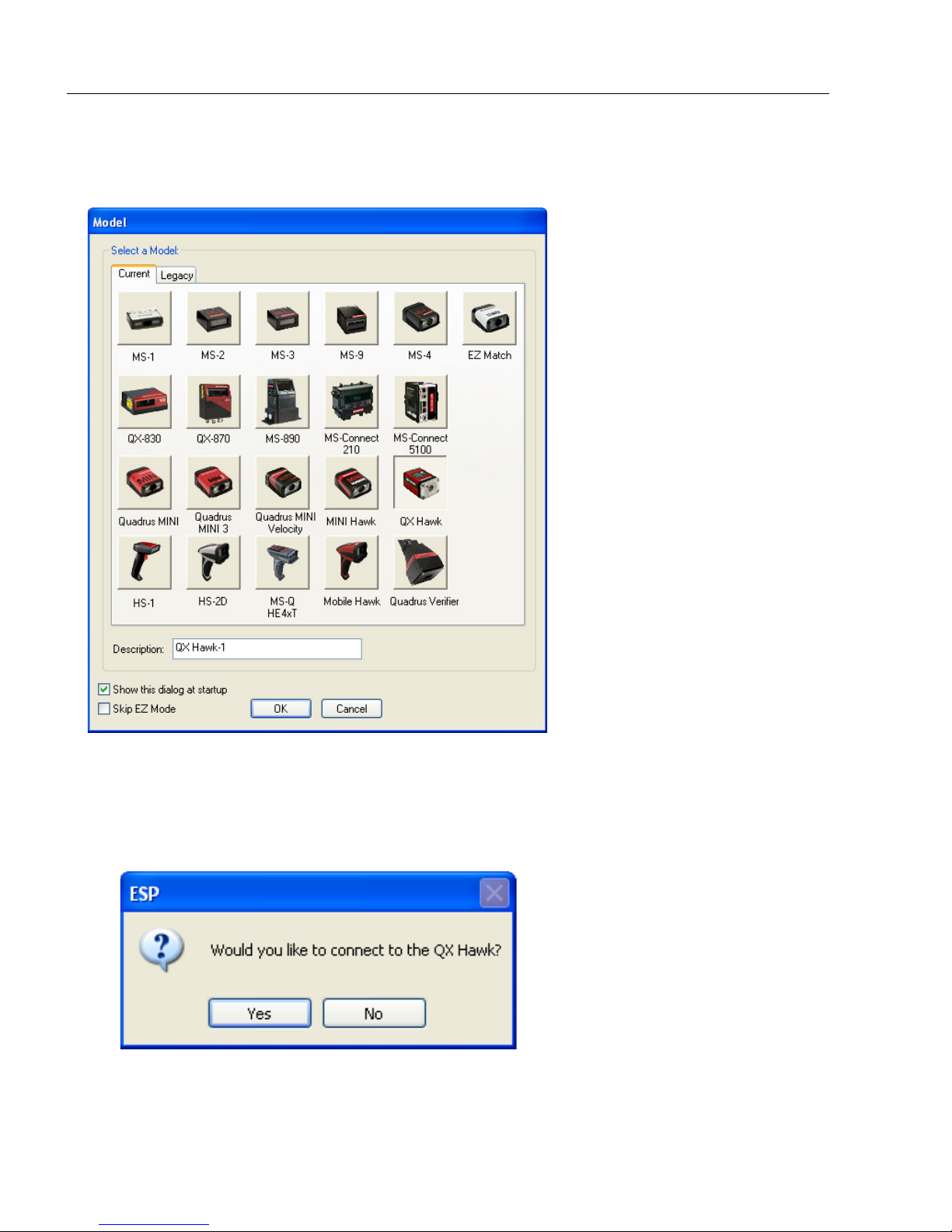
Select Model
Step 5 — Select Model
When you start ESP, the model menu will appear:
1. Click the button showing the QX Hawk.
2. Click OK.
Note: You can also simply double-click the button showing your imager to make your
selection.
3. Click Yes when the following dialog appears:
Note: If you need to select another model later, click the Switch Model button near
the top of the screen or use Model > New Model in the menu toolbar.
1-6 QX Hawk Industrial Imager User’s Manual
Page 15
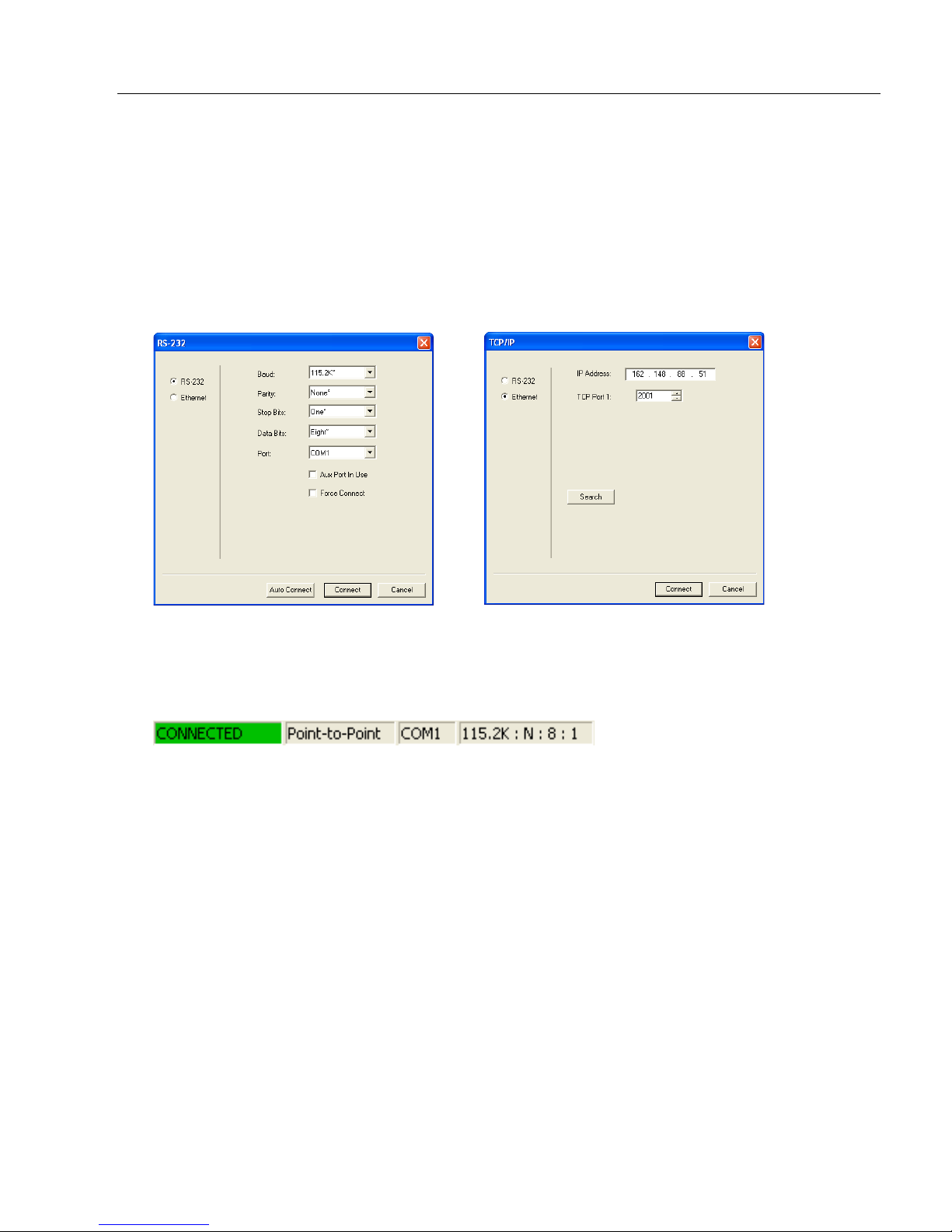
Step 6 — Connect
RS-232 Connection Wizard
Ethernet Connection Wizard
Connection Wizard
To connect using the Connection Wizard:
• Click Connect on the menu toolbar, and then select Connection Wizard.
•Select RS-232 or Ethernet to activate the appropriate display.
• Configure settings as required by the application, and click Connect.
Quick Start
• When a connection is established, the green indicator in the status bar at the bottom
right of the screen will be visible:
Important: The imager is in Continuous Read Mode by default. For best connection
results, be sure that no decodable symbols are within the imager’s field of view while
attempting to connect.
QX Hawk Industrial Imager User’s Manual 1-7
Page 16
Connect (cont.)
Step 6 — Connect (cont.)
Ethernet TCP/IP
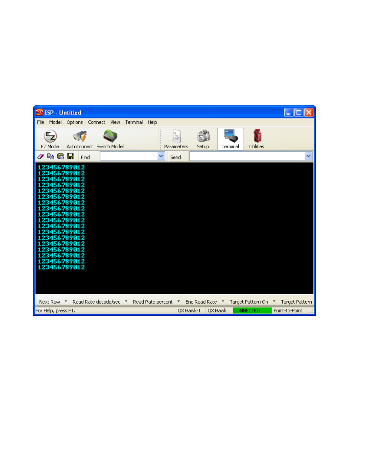
Once the QX Hawk is connected, incoming symbol data can be displayed in the Terminal,
as shown below.
1-8 QX Hawk Industrial Imager User’s Manual
Page 17
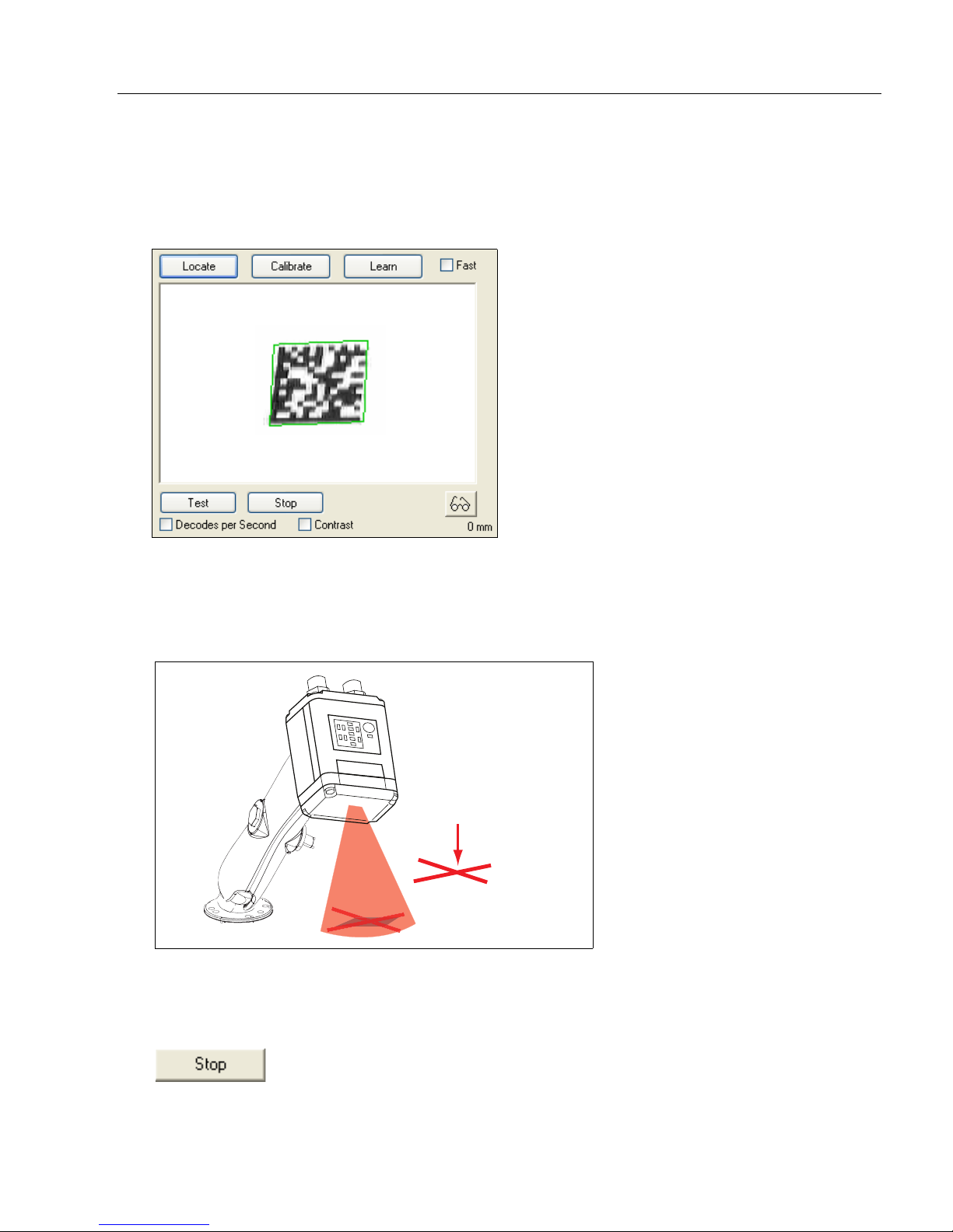
Quick Start
Center on object
in field of view.
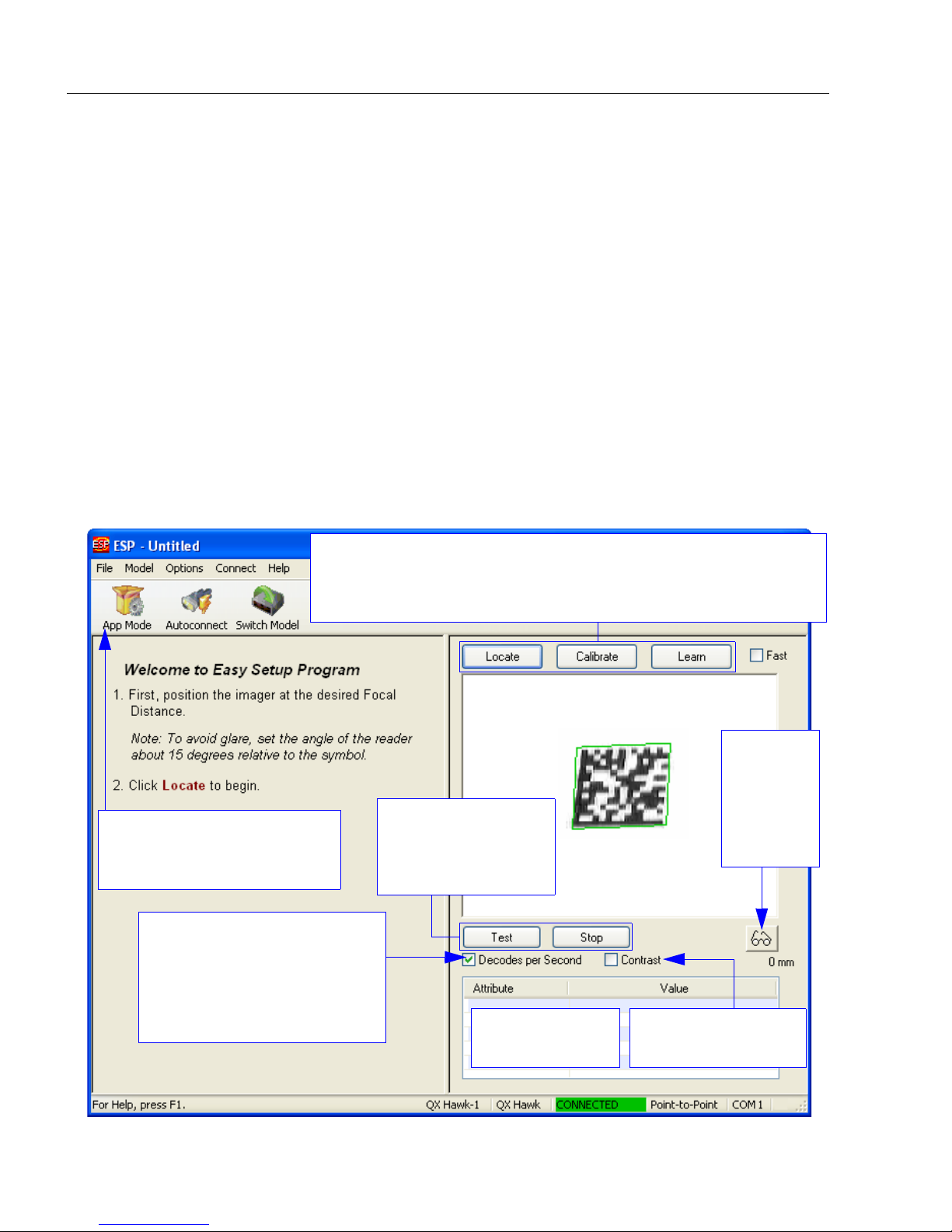
Step 7 — Locate Symbol
Locate by ESP
•In ESP’s EZ Mode, click the Locate button to enable the red X pattern.
The symbol in the field of view will appear in the video view beneath the Locate and
Calibrate buttons, and you will see the red target pattern projected from the front of the
imager.
• Center the target pattern on the symbol.
Important: The entire symbol should fall within the field of view (FOV) of the imager. The
field of view is what appears in ESP’s Locate/Calibrate window in EZ Mode.
• Click the Stop button to end the Locate function.
QX Hawk Industrial Imager User’s Manual 1-9
Page 18
Locate Symbol
EZ Button
Locate by EZ Button
If you are not connected to a host computer, the EZ Button allows you to locate a symbol
in the imager’s field of view.
• Hold down the EZ Button for about one second and release when you hear one short
beep. The amber
from the front of the imager.
• Center the target pattern on the symbol.
20%
LED will illuminate, and you will see the red target pattern projected
Note: To end all EZ Button functions, press the EZ Button once and quickly release.
1-10 QX Hawk Industrial Imager User’s Manual
Page 19
Quick Start
Step 8 — Calibrate
Imager settings can be adjusted automatically for optimum performance by either the EZ
Button or by ESP.
During the calibration routine, the imager will flash its amber Read Rate percent LEDs and
illumination LEDs while searching camera settings and determining the best configuration
for decoding symbol data. Upon successful completion of this routine, a green LED pattern
will flash brightly and illuminate the symbol. If unsuccessful, the imager will emit 5 short
beeps and stop searching.
Calibrate by ESP
1. Click the Calibrate button.
2. The imager will search camera settings to determine the best configuration for decoding
symbol data.
A successful calibration will display a green frame around the symbol, and the following
message will appear: “Uploading all reader parameters.” After a moment the symbol
data will be presented in the field below the image display window.
Calibrate by EZ Button
1. Hold down the EZ Button for about two seconds and release when you hear two
short beeps. The 20% and 40% LEDs will illuminate.
2. The imager will search camera settings to determine the best configuration for decoding
symbol data.
Note: To end all EZ Button functions, press the EZ Button once and quickly release.
Calibrate by Serial Command
Send <@CAL> from a terminal program to begin auto-calibration.
QX Hawk Industrial Imager User’s Manual 1-11
Page 20
Test Read Rate
These LEDs represent the
percentage of Good Reads
per images captured.
20%
40%
60%
80%
100%
Step 9 — Test Read Rate
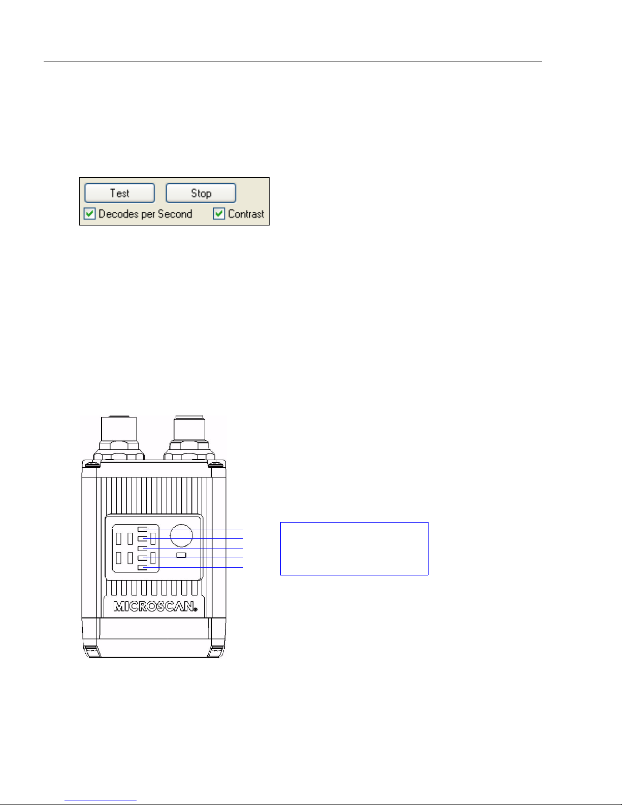
Read Rate indicates the number of successful decodes per second achieved by the imager.
Test Read Rate by ESP
1. Click the Test button to start the Read Rate test.
If a symbol has been successfully decoded, its data and related information will be
presented in the field below the image display window. While the symbol is being
decoded, the Read Rate LEDs will indicate the corresponding read rate percentage
on the top of the unit.
2. Click the Stop button to end the Read Rate test.
Note: Read rate can also be tested using the Read Rate interface in Utilities.
Test Read Rate by EZ Button
1. To start the Read Rate test, hold down the EZ Button about three seconds until you
hear three short beeps. The 20%, 40%, and 60% LEDs will illuminate.
While the symbol is being decoded, the Read Rate LEDs will indicate the corresponding
read rate percentage on the top of the unit.
2. To end the Read Rate test, press the EZ Button and quickly release.
Test Read Rate by Serial Command
You can also start a test with the <C> or <Cp> command and end it with the <J> command.
1-12 QX Hawk Industrial Imager User’s Manual
Page 21
Quick Start
Step 10 — Configure the Imager
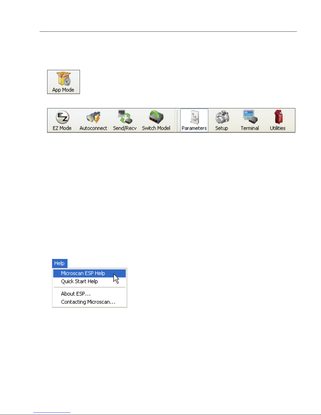
Click the App Mode button to make configuration changes to the imager.
The following modes are accessible by clicking the buttons at the top of the screen:
• Click the EZ Mode button to return to EZ Mode.
• Click the Autoconnect button to establish communication.
• Click the Send/Recv button to send or receive commands.
• Click the Switch Model button to open the model menu, or to return to a previous model.
• Click the Parameters button to show the tabbed tree controls for Communication, Read
Cycle, Symbologies, I/O Parameters, Symbol Quality, Matchcode, and Diagnostics.
• Click the Setup button to access the Camera Setup tree control and the tabbed interfaces
for Video, Evaluation, Calibration, Window of Interest (WOI), Configuration Database,
Ordered Output, Output Format, and Dynamic Setup.
• Click the Terminal button to display decoded symbol data and to send serial commands
to the imager using text or macros.
• Click the Utilities button to show the tabbed interfaces for Read Rate, Counters, Device
Control, Differences from Default, Master Database, and Firmware.
For further details, see ESP Help in the dropdown Help menu.
QX Hawk Industrial Imager User’s Manual 1-13
Page 22
Save Changes
1. Left-click on the +
to expand the
desired tree.
2. Double-click on the
desired parameter
and click once in the
selection box to view
options.
5. Right-click on the open
screen and select Save to
Reader to implement the
command in the imager.
4. Left-click again on the
open screen to complete
the selection.
3. Place the cursor in
the selection box,
scroll down to the
setting you want to
change, and click
once on the setting.
Step 11 — Save Changes
To make changes to configuration settings in the tree controls:
Saving Options
• Send, No Save. Changes will be lost when power is re-applied to the imager.
• Send and Save. This activates all changes in current memory and saves to the imager
for power-on.
1-14 QX Hawk Industrial Imager User’s Manual
Page 23

2 Using ESP
EZ Mode........................................................................................................................................2-2
App Mode......................................................................................................................................2-3
Menu Toolbar................................................................................................................................2-4
Navigating in ESP .......................................................................................................................2-15
Send/Receive Options ................................................................................................................2-16
Contents
This section explains the basic structure and elements of ESP (Easy Setup Program).
When ESP is opened, unless otherwise specified in ESP Preferences, the EZ Mode view
will appear. App Mode contains several tree controls (Communication, Read Cycle,
Symbologies, I/O Parameters, Symbol Quality, Matchcode, and Diagnostics), a
Setup interface, a Terminal interface, and a Utilities interface.
ESP can be used to configure the QX Hawk in three different ways:
• Graphic User Interfaces: Imager settings can be configured using such point-and-click
tools as buttons, spin boxes, check boxes, and drag-and-drop functions.
• Tree Controls: Each tree control contains a list of all command settings that pertain to
that specific area of imager operation. Each parameter can be configured using dropdown
menus or fields where characters can be entered.
•
Terminal: ESP
directly to the imager by typing them in the provided field.
’s
Terminal
allows the user to send serial configuration and utility commands
Information about using specific commands in ESP is provided in subsequent sections.
For
ESP
system requirements, see
QX Hawk Industrial Imager User’s Manual 2-1
Minimum System Requirements
in Chapter 1,
Quick Start
.
Page 24
EZ Mode
Click the App Mode button
to access configuration trees
and other setup features.
Symbol data is
displayed here.
Click the App Mode button
to access configuration trees
and other setup features.
Click Test button to
start the Read Rate
test and click Stop
to end the test.
Click
here to
initiate
a sliding
focus
control.
When Decodes per Second
is checked, the read rate test
displays how many decodes
the imager achieves each
second, instead of displaying
a percentage.
Contrast brightens
the image.
Click
Locate
to find and display the symbol. Click
Calibrate
to begin the
calibration routine. Calibration is also explained in
Quick Start
. Click
Learn
to save information about the next Data Matrix symbol decoded.
EZ Mode
EZ Mode allows the user to test read rate and calibrate the imager. After connecting to the
imager, the
testing, and calibration.
Locate/Calibrate/Learn
The calibration routine optimizes the imager by comparing Read Rates at various camera
and image processing settings. Click
it in the video view. Then click Calibrate to begin the calibration routine. The Learn button
allows you to save information about the next Data Matrix symbol decoded, which allows
faster and more consistent processing.
Test
Click the Test button to start the Read Rate test for a quick indication of the imager’s read
capabilities and the limits of the application. When Decodes per Second is unchecked,
the test will count the percentage of decodes relative to the number of actual scans. Click
Stop to end the test.
EZ Mode
view will appear. On-screen instructions assist the user with positioning,
Locate
to find the symbol in the field of view and display
2-2 QX Hawk Industrial Imager User’s Manual
Page 25
Using ESP
Click here to open
the Terminal view.
Menu toolbar
Click this icon to
return to EZ Mode.
Read Rate,
Counters,
Device Control,
Differences
from Default,
Master Database,
Firmware
Video, Evaluation, Calibration, WOI, Configuration Database,
Ordered Output, Output Format, Dynamic Setup
Autoconnect to the
imager,
Send and
Receive
command
settings, and
Switch Model.
Symbol data is
displayed here.
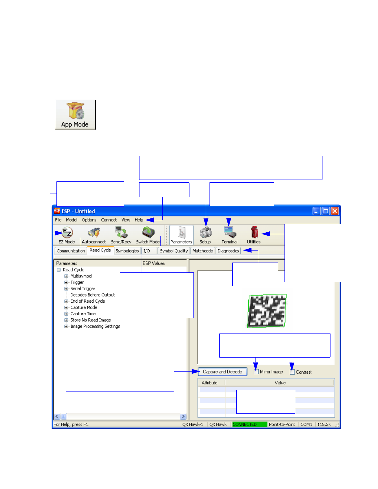
Click Capture and Decode to
decode the symbol in the field of
view, and to see a high resolution
image capture of the symbol.
Mirror Image reverses the image.
Contrast brightens the image.
Tabbed tree
controls
App Mode
From EZ Mode, click on the App Mode button to access the tabbed tree controls in
Parameters, the intuitive user interfaces in Setup, the Terminal interface, and the Utilities
interface.
Note: The App Mode and EZ Mode buttons appear in the same position to allow easy
switching between these primary modes.
QX Hawk Industrial Imager User’s Manual 2-3
Page 26
Menu Toolbar
(Save to Imager)
(Receive Imager
Settings)
Menu Toolbar
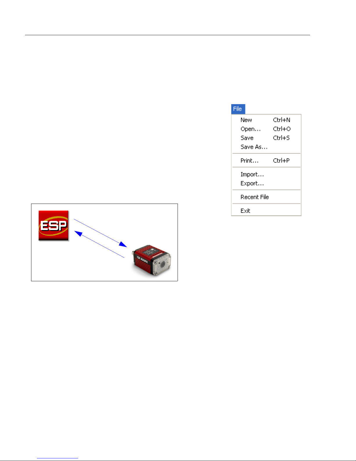
File
New
Whenever New is selected, the default configuration of ESP is
loaded.
Open/Save
When Save or Save As is selected, the ESP configuration is
saved to the host computer’s hard drive and available whenever
the same file is selected under Open.
Important: When configuration changes are saved to the hard
drive, these changes are not automatically saved to the imager.
The illustration below shows how settings can be saved and
received between ESP and the imager, and ESP and the host
hard drive.
Import/Export
Import converts the ASCII settings from a text file to ESP configuration settings.
Export converts the active ESP configuration settings to an ASCII text file.
2-4 QX Hawk Industrial Imager User’s Manual
Page 27
Using ESP
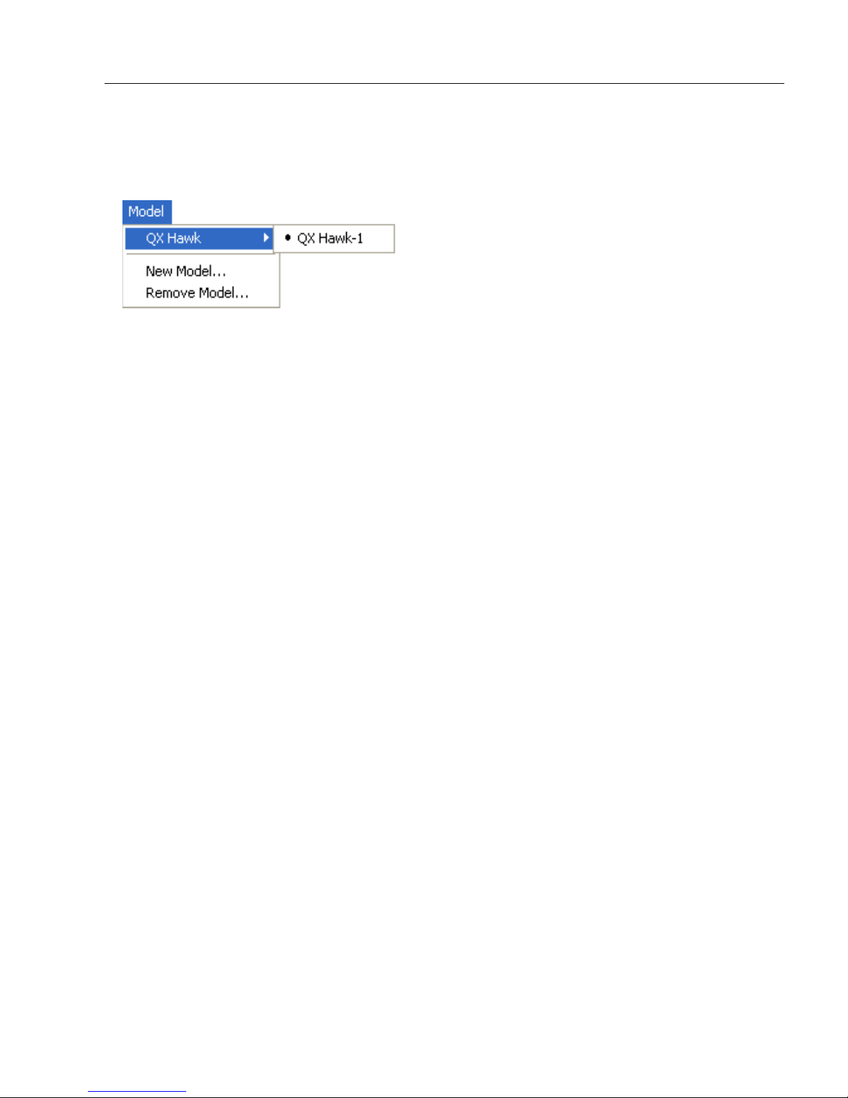
Model
The Model dropdown menu shows a list of recent imagers that have been used with ESP.
When a different model is chosen, the connection to the present model is terminated.
To connect to another model, select New Model, choose a new model from the pop-up
menu that appears, and click OK.
Note: When an ESP file is saved, the settings of all the models defined in that file are saved.
QX Hawk Industrial Imager User’s Manual 2-5
Page 28
Menu Toolbar
The Toolbar Style
options allow the user
to determine how ESP
will display the mode
options in the two rows
at the top of the screen.
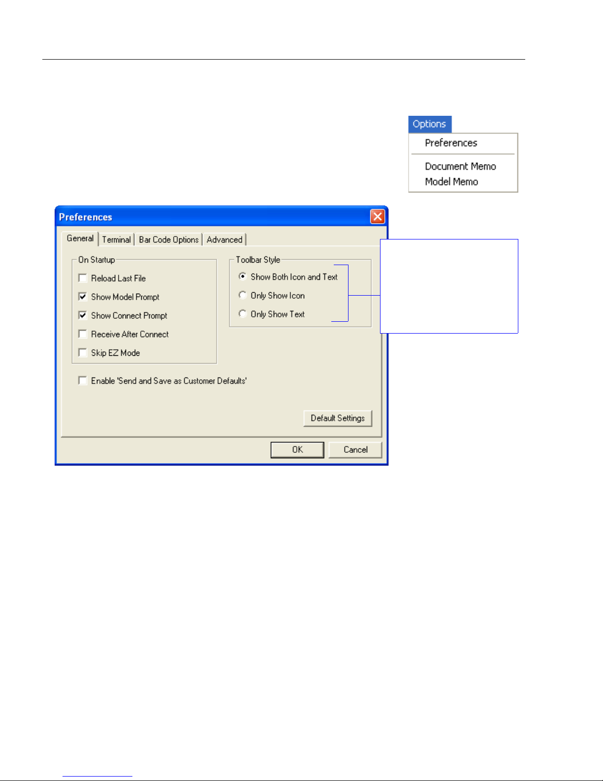
Options
The Options menu allows the user to save memos and set up
ESP Preferences.
Note: Preferences will be saved and loaded into ESP whenever
ESP is opened next, whether or not the ESP file is saved.
Preferences > General Tab
Reload Last File
At startup, reloads the last file saved to the host computer’s hard drive.
Show Model Prompt
At startup, shows the model menu displaying all supported readers.
Show Connect Prompt
At startup, displays the Would you like to connect to the QX Hawk? prompt.
Receive After Connect
At startup, loads the imager’s settings into ESP. (This is not recommended if ESP settings
are needed for future use.)
Skip EZ Mode
At startup, skips EZ Mode and opens directly in App Mode.
Enable ‘Send and Save as Customer Defaults’
At startup, enables the Send and Save as Customer Defaults option in the Send/Recv
command.
2-6 QX Hawk Industrial Imager User’s Manual
Page 29
Using ESP
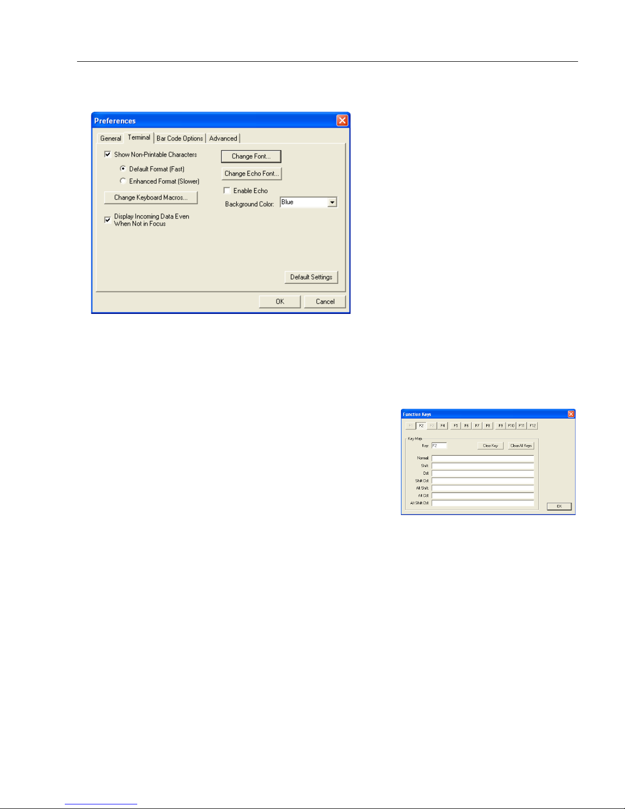
Preferences > Terminal Tab
Show Non-Printable Characters
When Show Non-Printable Characters is enabled, characters such as “CRLF” will be
displayed in the Terminal window. When Enhanced Format is checked, the characters
are displayed with more detailed formatting.
Change Keyboard Macros
Clicking the Change Keyboard Macros button brings
up the Function Keys dialog. In this dialog, select the
desired function key and then enter the macro keystrokes
in the associated key map. For example, to make
the keystroke to send a trigger character, select F2, then
in the Ctrl row, enter <trigger character> and click OK.
Then whenever the Ctrl-F2 keystroke is pressed, the
trigger character will start the read cycle.
Note: The F1 key is reserved for opening ESP Help
and the F3 key is reserved for the Find Next function.
Ctrl-F2
Change Font
Allows the user to modify the font used for decode data received from the imager on the Terminal.
Change Echo Font
Allows the user to modify the font used for command characters typed into the Terminal.
Enable Echo
Allows the user to enter command characters in Terminal.
Display Incoming Data Even When Not in Focus
When Display Incoming Data Even When Not in Focus is enabled, data from the
imager will continue to appear in the Terminal even when ESP is not the top window.
QX Hawk Industrial Imager User’s Manual 2-7
Page 30
Menu Toolbar
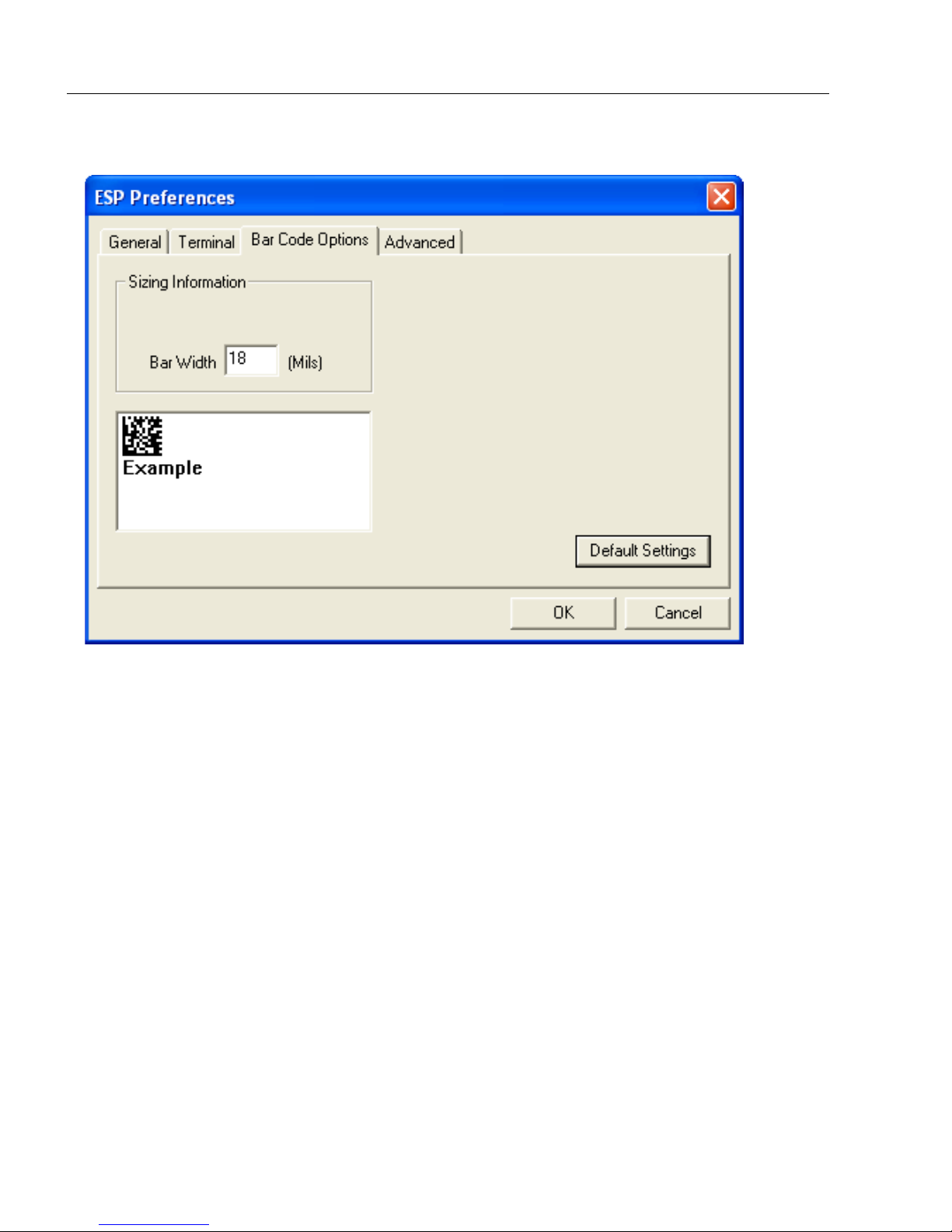
Preferences > Bar Code Options Tab
Sizing Information
Sets the bar height (in inches) and bar width (in
symbols.
Example: A bar width of 18 mils is 0.018 inches.
mils
, or thousandths of an inch) of user-created
2-8 QX Hawk Industrial Imager User’s Manual
Page 31

Using ESP
Preferences > Advanced Tab
The Auto Sync options at the top of the Advanced tab allow the user to determine
whether Auto Sync will be enabled automatically in sections of ESP where it is used, or if it
will ask before it enables Auto Sync functions.
Always Ask Before Auto Sync Occurs
If this option box is checked, specific Auto Sync functions can be enabled.
from the Reader will automatically send the imager’s settings to ESP when Auto Sync is
enabled.
settings chosen in
in which Auto Sync will not automatically send imager settings to
to the imager.
Send ESP Settings to the Reader
ESP
to the imager.
Do Not Send or Receive Settings
will automatically send all imager configuration
ESP
Receive Settings
creates a condition
, or send
ESP
settings
Show Target Pattern During Locate
Allows you to determine whether the blue LED target pattern will be on or off during the
Locate routine.
Show Target Pattern During Calibrate
Allows you to determine whether the blue LED target pattern will be on or off during the
Calibrate routine.
Use Higher Quality Images
Sets ESP to output images at a higher resolution than standard JPEG format.
Open Image after Save
When Open Image after Save is enabled, ESP automatically opens saved image captures.
Images can be saved from the Evaluation tab in the Camera view, or by right clicking an
image in any other image capture view and then saving.
Send XON with Autoconnect
Sends an
routine.
QX Hawk Industrial Imager User’s Manual 2-9
XON (Begin Transmission
) command to the imager before starting the
Autoconnect
Page 32

Menu Toolbar
Preferences > Advanced Tab (cont.)
Ask to Save ESP File when Quitting
When enabled, prompts the user to save a .esp file when ending a session.
The .esp file will be saved in the location specified by the user.
Connect to Readers via TCP/IP
When enabled, shows the TCP/IP Connection Wizard by default.
Use Default Storage Location
When enabled, automatically stores data in ESP’s Application Data folder.
2-10 QX Hawk Industrial Imager User’s Manual
Page 33

Using ESP
Document Memo
The information entered in the Document Memo field will appear in a context-sensitive text
box whenever the cursor hovers over the Document Memo item on the Options menu.
Model Memo
Similar to Document Memo, the information entered in the Model Memo field will appear in
a context-sensitive text box whenever the cursor hovers over the Model Memo item on the
Options menu. Memos created in Model Memo are specific to the model enabled when
the message was created.
Note: Memos must be saved in a .esp file to make them available in the next session. If
the current session is not saved, any memos that have been entered during the session
will be discarded, and will be unavailable in the next session.
QX Hawk Industrial Imager User’s Manual 2-11
Page 34

Menu Toolbar
RS-232 Connection Wizard
Ethernet Connection Wizard
Click the Search
button to locate
imagers on the
network.
Connect
The Connect dropdown menu allows the user to access the Connection Wizard, as well
as the Autoconnect and Configure Multidrop dialogs. Connect and Disconnect can
also be performed directly from the dropdown menu without opening a dialog.
Connection Wizard
To connect using the Connection Wizard:
• Click Connect on ESP’s menu toolbar, and then select Connection Wizard.
• Select RS-232 or Ethernet to activate the appropriate display.
• Configure RS-232 or Ethernet settings as required by the application, and click Connect.
• When a connection is established, the green indicator in the status bar at the bottom
right of the screen will be visible:
2-12 QX Hawk Industrial Imager User’s Manual
Page 35

Using ESP
• Once the correct
port is chosen,
click Start to
connect.
Autoconnect
•
If the RS-232 connection attempt fails, use
the imager and the host.
• If the communication port is not the default COM1, use the dropdown menu to change
the port.
Autoconnect
to establish a connection
between
• When a connection is established, the green indicator in the status bar at the bottom
right of the screen will be visible.
QX Hawk Industrial Imager User’s Manual 2-13
Page 36

Menu Toolbar
Drag specific configuration
values from the control tree
directly into this field to
encode new symbols.
Choose a spatial
orientation for the
new symbol.
Create a caption
for the symbol
that matches or
describes the
encoded data.
The symbol will be
displayed in the field
at the bottom of the
Bar Code Dialog.
View
The View menu allows the user to move quickly between the
Parameters, Setup, Terminal, and Utilities interfaces without
using the icon buttons on the App Mode toolbar. It also allows
the user to access the Bar Code Dialog, shown below.
Bar Code Dialog
Symbols can be created in the Bar Code Dialog by typing the
text to be encoded. This is a useful tool for creating configuration
symbols, allowing the user to configure the imager by reading the
user-created symbols.
2-14 QX Hawk Industrial Imager User’s Manual
Page 37

Using ESP
1. Left-click on the + to expand
menu items.
2. Double-click the desired
parameter and single-click
in the selection box to view
options.
3. Place the cursor in the
selection box, scroll down
to the desired setting, and
single-click the setting.
4. Left-click again on the open screen to complete the
selection.
5. Right-click on the open screen and select Save to
Reader to implement the command in the imager.
The command can be sent without saving, or sent
and saved simultaneously.
The X
indicates
that the
setting is
default.
Navigating in ESP
To change imager settings, or to access the Setup, Terminal, or Utilities views, click the
App Mode button.
To return to EZ Mode, click the EZ Mode button.
To make changes to configuration settings in the tree controls:
QX Hawk Industrial Imager User’s Manual 2-15
Page 38

Send/Receive Options
Send/Receive Options
To access Receive, Save, and Default options, click the Send/Recv button. These
options can also be reached by right-clicking in any of the configuration views.
Receiving
From the Send/Recv menu, select Receive Reader Settings.
Caution: Selecting this option will upload the imager’s settings. If the ESP file has a
number of custom settings that must be maintained and downloaded into the imager,
these settings will be lost.
This function is useful for receiving (uploading) the imager’s settings and saving them as a
file for future use. For example, if the imager has settings that must not change, Receive
Reader Settings would load those settings to ESP and save them in an ESP file for later
retrieval.
Receiving the imager’s settings will also assure that any unwanted subsequent changes in
ESP will not be saved.
Saving
Send, No Save (<A>)
Saves ESP settings to current
memory.
Send and Save (<Z>)
Activates all changes in current
memory and saves to the imager
for power-on.
Send and Save as Customer Defaults (<Zc>)
Saves default settings for quick retrieval.
This option will be visible only if Enable ‘Send and Save as Customer Defaults’ is
checked in ESP Preferences.
2-16 QX Hawk Industrial Imager User’s Manual
Page 39

Using ESP
Defaulting
When Default Current Menu Settings or Default all ESP Settings are selected, only the
ESP settings are defaulted.
Advanced Options
Send Current View
This is the same as
>
Send No Save
commands in the current configuration
tree are sent.
Save to Reader
except that only the
Send Current Command
This is the same as
View
, except that it saves only the
command that is currently selected.
Send Current
Add/Remove Exception
After a Receive Reader Settings command is performed1 and the Add Exception option
is selected, a list of serial commands may appear. These are commands that may be in
the imager’s firmware, but are not included in, or are different from, the current version of
These commands can be edited by double-clicking them and changing them as needed.
It is important to note that these commands will be saved to the imager whenever a Save
to Reader command is sent, or when an <A> or a <Z> command is sent.
Also, if there is a corresponding ESP menu item, the ESP Value column for that item will
be blank following a Receive Reader Settings command.
ESP
.
1. From the Send/Recv button or by right-clicking in any blank section of a tree control view.
QX Hawk Industrial Imager User’s Manual 2-17
Page 40

Send/Receive Options
2-18 QX Hawk Industrial Imager User’s Manual
Page 41

3 Hardware Integration
Connectors ................................................................................................................................... 3-2
Cordsets ....................................................................................................................................... 3-3
QX Hawk and QX-1 Connectors and Pinouts...............................................................................3-4
Power and Trigger Switching........................................................................................................ 3-8
Port Routing.................................................................................................................................. 3-9
Application Examples ................................................................................................................. 3-10
Contents
This section introduces the details of QX Hawk hardware, and explains how that hardware
can be integrated in an application.
QX Hawk Industrial Imager User’s Manual 3-1
Page 42

Connectors
Ultra-Lock Connector
Traditional Threaded Connectors
Connectors
Industrial cabling and connectivity schemes must be able to withstand environmental
extremes of heat, cold, and moisture, and be secure enough not to be disconnected or
damaged inadvertently in the course of day-to-day operation.
The current industry standard for connectivity is a sealed, circular connector such as the
M12. The International Electrotechnical Commission (IEC) standard for M12 connectors
describes them as fixed
available off-the-shelf from manufacturers
Molex, or Binder.
The QX Hawk uses sealed, circular connectors with Ultra-Lock™ technology. Ultra-Lock
connectors are more resistant to harsh industrial conditions, and are easy to connect.
Ultra-Lock Connectors
Microscan has adopted Ultra-Lock connectivity because of speed, ease-of-use, and
ingress protection considerations. The main advantage of the Ultra-Lock system is that
only two steps are required at every connection point:
1. Align the connector and receptacle keys;
2. Push the connector into place. (Do not twist the connector, as this can bend the pins.)
Ultra-Lock connectors are “operator-independent”. This means that they are not subject to
under-tightening or over-tightening, both of which are common problems with screw-down
connectors, and both of which undermine the moisture-resistant seal.
and free screw-locking connectors. This type of connector is widely
such as Turck, Lumberg, Phoenix Contact,
Another advantage of the QX Hawk’s Ultra-Lock connectivity scheme is that the Ultra-Lock
receptacles on the imagers and the QX-1 Interface Device also accept screw-down connectors,
giving users the flexibility to use either Ultra-Lock or screw-down connectors.
“Ultra-Lock” is a trademark of Woodhead (Molex).
3-2 QX Hawk Industrial Imager User’s Manual
Page 43

Hardware Installation
M12 Ultra-Lock to RJ45 (Ethernet) Cordset
M12 Ultra-Lock to M12 Ultra-Lock Cordset
M12 Ultra-Lock to Photo Sensor Cordset
Cable with flying leads
Cordsets
The terms “cordset” and “cable” are both applicable to industrial connectivity, but they are
not synonymous. Cordsets enable communications and power between imagers and
interface devices. Cordsets have an M12 Ultra-Lock connector at one or both ends.
Examples of cordsets are shown below.
Cables do not have M12 Ultra-Lock connectors at either end. An example of a cable is
shown below.
QX Hawk Industrial Imager User’s Manual 3-3
Page 44

QX Hawk and QX-1 Connectors and Pinouts
Ground
Output 3
Output 1
Output 2
New Master
Default
Power
Input Common
Output Common
RS-232 RxD
Trigger
RS-232
TxD
QX Hawk (Back View)
Input
Common
RS-422/485 RxD (–)
RS-232 TxD/
RS-232 RTS
Trigger
RS-232 RxD/
RS-232 CTS
Power
Ground
RS-422/485
RxD (+)
RS-422/485
TxD (+)
RS-422/485 TxD (–)
Input 1
Te rm i na t ed
A (Serial) M12 12-pin Plug
B (Serial) M12 12-pin Socket
A is a serial M12 12-pin plug.
B is a serial M12 12-pin socket or an Ethernet M12
8-pin socket.
TX (+)
RX (–)
RX (+)
TX (–)
Te rm i na t ed
Te rm i na t ed
B (Ethernet) M12 8-pin Socket
Terminated
Terminated
QX Hawk and QX-1 Connectors and Pinouts
When deploying a network of imagers and interface devices in an industrial setting, it is
important to use components whose pin assignments are arranged in a way that avoids
communication errors and equipment damage. This can be achieved with components
that are designed in a logical, consistent, and easy-to-implement way.
The QX Hawk has a very simple pin assignment methodology. The clearly identified connectors
at the back of the unit can be used to receive and bus power, and also to send and receive
data and commands.
See Appendix C – Ground and Shield Considerations for information about grounding
the imager correctly.
3-4 QX Hawk Industrial Imager User’s Manual
Page 45

Hardware Installation
An earth ground is provided through the cable shields and chassis of the imager.
QX Hawk
Grounding the QX Hawk
Proper grounding is necessary for operator safety, noise reduction, and the protection of
equipment from voltage transients. Buildings, including any steelwork, all circuits, and all
junction boxes must be grounded directly to an earth ground in compliance with local and
national electrical codes.
Ground Loops
Ground loops (signal degradation due to different ground potentials in communicating
devices) can be eliminated or minimized by ensuring that both the host, imager, and their
power supplies are connected to a common earth ground.
QX Hawk Industrial Imager User’s Manual 3-5
Page 46

QX Hawk and QX-1 Connectors and Pinouts
Expected Power and Ground Connections for Proper Operation
Grounding Notes:
• Ensure that mounting bracket “Earth” is at the same potential as power source “Earth”.
• Supply “Return” and “Earth” ground must be stable, low-impedance reference points.
• “2-Terminal Power Supply” must still provide an “Earth” connection to the imager.
• “Signal Ground” can be used for communications and/or discrete signal ground reference.
It must not be used as Power Ground or Earth Ground.
3-6 QX Hawk Industrial Imager User’s Manual
Page 47

Hardware Installation
Connectors 1 and 3 are 12-pin plugs, and Connector 2 is a 12-pin socket.
All three connectors can be assigned to bus power and data as required by
the application.
The two switches at the center of the device allow the user to route signals
as needed.
Pin Assignment
1 + 10-28V
2
Trig/NM/Input 1
Common
3 Ground
4 Trigger
QX-1 Interface Device
QX-1 Trigger Connector 4-pin Socket
PWR
TRIG
1, 3,
T
1, 2,
3, T
1, 2,
3
1, 3
This simple diagram (shown on the base of the QX-1) illustrates how
power, communications, I/O, and trigger signal can be routed through
the QX-1 device depending on the needs of the application. The
switches greatly increase signal routing flexibility.
QX-1 Communications - I/O -
Power - Trigger
QX-1 Interface Device
The QX-1 Interface Device’s receptacles are physically the same as those on the QX Hawk,
but they do not have explicit pin assignments. The QX-1 allows users to bus power and
communications as required by the application.
QX Hawk Industrial Imager User’s Manual 3-7
Page 48

Power and Trigger Switching
PWR
TRIG
1, 3,
T
1, 2,
3, T
1, 2,
3
1, 3
Power can be bussed between imagers and interface
devices. At each location on a network where a new power
supply is added, the Power switch on the QX-1 can be
used to break power between Connector 2 and Connectors
1, 3, and T.
The Trigger signal between Connector 2 and Connectors
1, 3, and T can be broken using the Trigger switch. This
isolates trigger signals as required by the application.
Power and Trigger Switching
3-8 QX Hawk Industrial Imager User’s Manual
Page 49

Hardware Installation
RS-232 A, RS-232 B, and RS-422 are
serial. RS-232 A is always enabled. RS-232
B and RS-422 can be enabled or disabled to
match the physical requirements of the
application. Ethernet can also be enabled
or disabled as required.
RS-232 A, RS-232 B, and RS-422 can be
configured for Baud Rate, Parity, Stop Bits,
Data Bits, Symbol Data Output, Extra Symbol
Information (Decodes Before Output, Symbol
Position Output, etc.), Diagnostics Output,
and External Source Processing Mode
(Command or Data).
Ethernet can be configured for IP Address,
Subnet Mask, Gateway, IP Address Mode,
Symbol Data Output, Extra Symbol Information, Diagnostics Output, and External
Source Processing Mode.
Port Routing
The physical advantages created by flexible signal routing and switching are enhanced
further by Port Routing, which can be configured in ESP. Port Routing eliminates the
need for dedicated “Host” and “Aux” ports in a traditional sense. With Port Routing, any
port can be defined as a Host or Aux port. Port Routing also allows users to define the
data types that are accessible from specific ports.
The primary benefit of Port Routing is that any type of data can be routed to any port, and
can be sent through multiple ports simultaneously. Multiple types of data can also be
appended to the symbol data that is output from the imager to the host. Command data,
symbol data, extra symbol information, and diagnostic data are enabled by default in the QX Hawk.
The table below lists different types of data, with examples for each data type.
Data Type Example
Command Data Serial commands; imager responses to serial commands.
Symbol Data Any string of data encoded in a symbol.
Extra Symbol Information Decodes per trigger, decode direction, configuration database index number.
Diagnostic Data Service message.
The screen capture below (from ESP) shows the QX Hawk’s four communications ports
and the parameters for each.
QX Hawk Industrial Imager User’s Manual 3-9
Page 50

Application Examples
Application Examples
The following examples demonstrate how the components described in previous pages
can be deployed in industrial applications.
Daisy Chain
Daisy chain configurations are used in applications such as product packaging, where
single items have multiple symbols. For example, a box with one symbol on the top and
symbols on either side requires at least three imagers to ensure that all symbols will be
decoded.
The highlighted areas below demonstrate how a daisy chain can be arranged. One imager
is placed above the conveyor line and one imager is placed on each side of the line. The
three imagers essentially function as a single imager, and data is sent from the primary
imager to the host or PLC.
Important: Do not attempt to power more than four imagers with a single power supply in
a daisy chain configuration. Add a QX-1 and one power supply for every four additional
imagers in the daisy chain.
3-10 QX Hawk Industrial Imager User’s Manual
Page 51

Hardware Installation
Multidrop
Multidrop networks are used in applications where it is necessary to decode symbols at
multiple locations within an industrial process. Imagers are placed at stations located
between manufacturing steps, and data from those imagers is directed to a multidrop
concentrator before being sent to a host. An example of this type of application is food
packaging, in which part number data is collected and tracked throughout the packaging
process.
The highlighted areas below demonstrate how a multidrop network can be arranged.
QX Hawk Industrial Imager User’s Manual 3-11
Page 52

Application Examples
Ethernet TCP/IP
Ethernet TCP/IP is the standard Ethernet interface used to connect multiple locations in a
network, such as computers in an office network. It can also be used to network other
communications devices, such as imagers and PLCs on a factory floor.
The highlighted areas below demonstrate how an Ethernet daisy chain can be arranged.
Ethernet-enabled imagers can also be set up in standalone configurations, or multiple
Ethernet-enabled imagers along a production or packaging line can be connected to Ethernet.
3-12 QX Hawk Industrial Imager User’s Manual
Page 53

4 Setup
Video.............................................................................................................................................4-2
Evaluation ................................................................................................................................... 4-11
Calibration................................................................................................................................... 4-14
Window of Interest ......................................................................................................................4-15
Configuration Database .............................................................................................................. 4-17
Ordered Output........................................................................................................................... 4-24
Output Format............................................................................................................................. 4-28
Dynamic Setup ........................................................................................................................... 4-32
Contents
This section describes ESP’s Setup interfaces: Video, Evaluation, Calibration, Window
of Interest, Configuration Database, Ordered Output, Output Format, and Dynamic
Setup. Each interface allows the user to make changes to imager configuration quickly
and easily.
QX Hawk Industrial Imager User’s Manual 4-1
Page 54

Video
Allows the user to take an
image capture of the
symbol in the field of view
at any time, and to
decode the symbol data.
Similar to the Capture
and Decode function in
the Configuration views.
Initiates the Test routine.
Allows the user to test the
imager’s read rate and
decodes per second, and also
displays decoded symbol data
in the field at the bottom of the
screen, Click Stop to end the
Test routine.
Clicking this icon enables the
focal distance slide control to
the right of the video view.
The focal distance value is
displayed just below the icon.
When enabled, shows the
symbol in higher contrast
than the default contrast
value.
Activates the imager’s target
pattern and initiates live
video display of the symbol
in the field of view.
Initiates Calibration routine. Initiates Data Matrix Learn operation.
Initiates Select
Reader Optics dialog.
Symbol data and
Test results are
shown in this field.
When Decodes per Second is checked,
the read rate test displays how many
decodes the imager achieves each second,
instead of displaying a percentage.
Video
The Video view allows the user to perform the same Locate, Calibrate, and Test routines.
There is also a focal distance adjustment tool to the right of the video view.
Video also features simple Capture and Decode functionality.
4-2 QX Hawk Industrial Imager User’s Manual
Page 55

Camera Setup
Click the App Mode button and then the Setup button.
You will see the Camera Setup tree control to the right of the Video interface.
To open nested options,
single-click the +.
To change a setting,
double-click the
setting and use the
cursor to scroll
through the options.
The * indicates
that the setting
is the default.
Setup
Note: Communication settings can also be sent to the imager from ESP’s Terminal using
Microscan’s K command format.
QX Hawk Industrial Imager User’s Manual 4-3
Page 56

Camera Setup
Camera Settings
Gain
Sets the gain value for the image sensor. This setting can be configured through autocalibration,
and is the recommended method for configuring this settings. A higher can value will
increase the brightness of the image, but the noise performance of the system is reduced.
Prior to configuring the gain, the required shutter speed should be set, and the gain should
be configured to optimize the shutter speed setting.
Shutter Speed
This value sets the exposure or integration time for the image sensor pixels. The shutter
speed setting in relation to the speed of the object is critical. If an object is moving fast and
a slow shutter speed is selected, blurring or smearing of the object will occur. As shutter
speed is increased the amount of light required or gain needed has to be increased since
the pixels exposure time has decreased.
4-4 QX Hawk Industrial Imager User’s Manual
Page 57

Setup
Illumination Type
Mode
Configures the illumination pattern. “Bright Field” is used for most applications. The other
modes are reserved for future feature enhancements.
For Mode4, the internal illumination is always off, similar to configuration setting 0 (Always
Off).
Brightness
Configures the amount of illumination output from the unit’s built-in lighting.
QX Hawk Industrial Imager User’s Manual 4-5
Page 58

Camera Setup
Focus Distance
Provides focal distance adjustment for the camera.
When “Distance units” is set to “millimeters”, the Focal Distance parameter has a range of
25 to 4000. Any value outside this range will be rejected.
When “Distance units” is set to “1/100 inch”, Focal Distance is limited to a range of 100 to
4000. If the user attempts to set the Focal distance to less than 100 (1 inch), the parameter
will be set to 100.
When a lens is changed on the QX Hawk, the user can improve the accuracy of the Focal
Distance parameter by using the <@OPTIC> command.
Even after running <@OPTIC> the system distance accuracy is approximate. The command
gives reasonable step sizes as apposed to completely unknown magnitudes but it is not
expected that 2 units will exhibit the same exact focus for a given setting.
Distance Units
Defines the measurement unit value of the Focal Distance parameter.
Required Focal DistanceDistance Units = millimeter (0) Distance Units = 1/00 inch (1)
4-6 QX Hawk Industrial Imager User’s Manual
Page 59

Setup
Lens Model
This value must reflect the correct camera lens currently installed on the product. This
value is properly configured after leaving factory. However, since the lens can be changed
by the user, this parameter needs to be updated to reflect the currently installed lens.
To verify lens type, turn off power to the QX Hawk (do not look into the targeting laser).
Then look at the outer rim of the unit’s camera lens. The following markings define the
correct “Lens Type” parameter value:
‘.’, and “15” = Lens Type 1
‘..’, and “30” = Lens Type 2
‘...’, and “45” = Lens Type 3
When a lens is changed on the QX Hawk, the user can optimize the accuracy of the Focal
Distance parameter by using the <@OPTIC> command.
This parameter is “sticky”. Once saved with a <Z> or <Zc> command, it can only be
“defaulted” with <Zrdall> or <K525d>.
QX Hawk Industrial Imager User’s Manual 4-7
Page 60

Camera Setup
Sub-Sampling
The camera can be enabled to sub-sample pixels in the specified image frame. Sub-sampling
can be specified as either 4:1 or 16:1, which signifies the sampling rate.
4:1
1 pixel output for every 4 pixels sampled. When selected the image will be sampled 2:1 in
the vertical direction and 2:1 in the horizontal direction for a combined 4:1 ratio. An image
with a dimension of 640 x 480 will be scaled to 320 x 240.
16:1
1 pixel output for every 16 pixels sampled. When selected the image will be sampled 4:1 in
the vertical direction and 4:1 in the horizontal direction for a combined 16:1 ratio. An image
with a dimension of 640 x 480 will be scaled to 160 x 120.
4-8 QX Hawk Industrial Imager User’s Manual
Page 61

Setup
Window of Interest
The active pixel area of the image sensor is defined as the “Window of Interest” (WOI).
This allows the user to select an area in the Field of View that the desired symbol will be
located. The programmable window of interest is useful for increasing decode speed,
improving threshold, selecting desired symbol from multiple symbols in FOV. The user
provides the upper-left pixel location and the size in both rows and columns to define the
Window of Interest.
Important Notes:
• The column width value is required to be a modulus 16 value, so regardless of the column
width setting that is configured the actual column width will be decreased (if required) to
a modulus 16 value. For example a column width value of 632 would actually be 640. A
user request of this setting would still return 632.
• The column pointer is required to be an even value, so regardless of the column pointer
setting that is configured the actual column pointer will be decreased (if required) to an
even value. For example a column pointer value of 101 would actually be 100. A user
request of this setting would still return 101.
Top
Defines the row position of the upper-left starting point of the image window.
Left
Defines the column position of the upper-left starting point of the image window.
QX Hawk Industrial Imager User’s Manual 4-9
Page 62

Camera Setup
Height
Defines the size, in rows, of the image window. Maximum value is defined as the Maximum
row size of Image sensor, minus the row pointer value.
Width
Defines the size, in columns, of the image window. Maximum value is defined as the Maximum
column size of Image sensor, minus the column pointer value.
4-10 QX Hawk Industrial Imager User’s Manual
Page 63

Setup
Evaluation
In Evaluation, you can view images
currently in the imager, capture and
decode a symbol, save it as a digital
file, and perform histogram and line
scan evaluations.
When you click on the Evaluation
tab, you will see the images that are
currently stored in the imager.
Click Receive to refresh this view.
Click Capture/Decode to display the
and decode event will occur, regardless
of read cycle settings.
Click Read to trigger a read cycle. If
there is enough time in the read
up to 32 good reads (or 6 full-scale
images) can be captured and displayed,
depending on the size of the images,
and depending on the number
enabled in Number of Captures
under Capture Mode in the Camera
Setup menu tree to the left of the
tabs.
If you click Save, the current image
will be saved to the location of your choice.
Note: An image can only be saved in the format in which it was uploaded to ESP. JPEG
images will be saved as .jpg, and bitmaps will be saved as .bmp.
When you click the JPEG Image box, notice that the Line Scan button is grayed out.
The JPEG option allows faster captures and transfers, but since the JPEG standard
compresses image data, it is not suitable for the more rigorous demands of line scan
evaluation.
JPEG also allows you to adjust the image quality (resolution) by adjusting the sliding tab
between 1 and 100, 1 being the lowest quality and 100 being the highest.
When possible, use the highest quality; when image transfer speed must be increased,
use a lower image quality setting. Adjustments for this setting will depend on your specific
hardware and software limitations.
cycle,
QX Hawk Industrial Imager User’s Manual 4-11
Page 64

Evaluation
Histogram
The
Histogram
is a graphic representation of the numeric count of the occurrence of each intensity (gray
level) in an image. The horizontal axis represents the values of gray levels, and the vertical
axis represents the number of pixels for each gray level.
Note: Since histograms are performed in the imager, the results will be saved regardless
of whether the image was uploaded as a JPEG (.jpg) or a bitmap (.bmp).
1. From the Evaluation window, click the Histogram button.
The current image is transferred into the histogram operation. This may take a
moment, since all the relevant pixels are being evaluated intensively.
2. When the Histogram window opens, you may need to expand the window and/or
adjust the scroll bars in order to bring the image into view.
3. To generate a histogram, click and drag your cursor diagonally across the symbol or
a portion of the symbol.
The image will be surrounded by an “area of interest box”, a dashed blue line with red
anchor points that can be selected and moved by placing a cursor inside the box, and
can be resized by clicking and dragging the anchor points.
function is useful in determining quality and contrast of symbols. A histogram
4-12 QX Hawk Industrial Imager User’s Manual
Page 65

Line Scan
1. From the Evaluation tab, click the Line Scan button. A window like that shown
below will appear.
2. Drag your cursor horizontally across the image.
This will create a dashed horizontal line. Pixel information and a visual representation
of the dark and light pixels will be displayed below the image.
Setup
When you center your cursor over the dashed line, it becomes a double arrow cross.
This allows you to move the line anywhere in the window. You can also use your
keyboard arrows to move the line incrementally in any direction.
As with the histogram, the line scan compares light and dark pixels, but in a spatial
distribution. On the Y axis of the graph below, 0 is black and 255 is white; the X axis
represents the horizontal axis of the symbol as described by the line scan.
When you click anywhere on the graph, a vertical red line appears at that point and its
position and value (in terms of black-to-white) are updated in the Pixel Info table to
the left of the graph (237 in this example). In addition, a horizontal dashed red line is
displayed that indicates the average value.
QX Hawk Industrial Imager User’s Manual 4-13
Page 66

Calibration
ESP’s Calibration interface shown
during a calibration routine
ESP’s Calibration interface shown
after a calibration routine
Calibration
The Calibration interface in ESP is a powerful and intuitive way to optimize the imager’s
performance. It allows the user to control several complex, simultaneous calibration
operations, and to follow the progress of those operations using cues such as progress
bars, real-time representations of calibration values, and other dynamic user feedback.
4-14 QX Hawk Industrial Imager User’s Manual
Page 67

Setup
Window of Interest
The active pixel area of the image sensor is called the Window of Interest (WOI). The WOI
allows the user to select an area of the field of view in which the desired symbol is located.
The programmable window of interest increases decode speed, improves threshold, and
makes it easy to select specific symbols from among several in the field of view. The user
provides the upper-left pixel location and the size of the window to define the Window of
Interest.
Caution: Window of Interest will shrink the field of view and therefore could cause symbols
to be missed in dynamic applications.
QX Hawk Industrial Imager User’s Manual 4-15
Page 68

Window of Interest
Window of Interest Graphic Interface
1. From the Camera menu, click the WOI tab to bring up Window of Interest.
If you haven’t already captured an image, click the Capture and Decode button to
decode the present image. If successful, the Good Read indicator on the WOI tab will
be green and the symbol will appear in the pane below.
Note: You can resize the image by clicking and dragging the ESP window from the
lower right corner. This is useful where very small symbols are being read.
2. Click and drag your cursor over the symbol that you want to isolate for reading.
Notice that the surrounding area goes black.
You can use the handles on the image area that you have just drawn to resize the
region of interest. You can also click on the center of the window of interest and move it.
3. Test the new settings in Read Rate Mode.
Note: To remove the window of interest, click the Reset button or click anywhere in
the WOI pane.
Note that all pixels not in the WOI are defined as black.
Because the imager has far less processing to do in a smaller window, read rates
typically increase dramatically. One possible downside is that the chance of missing
a symbol increases with the smaller window. Always verify that your WOI will be
large enough to allow for any random movement of symbols in your field of view.
4-16 QX Hawk Industrial Imager User’s Manual
Page 69

Setup
Configuration Database view, set for 5 Active Indexes, with Capture Settings highlighted
Configuration Database
The Configuration Database allows the user to manage multiple configuration profiles. It is
a useful tool in applications that require several different imager configurations to be
applied sequentially, and it allows the user to perform far more complex operations than
would be possible with only one set of configuration parameters.
As soon as the number of active database settings is something other than 0, the database
is enabled. Once enabled, the current configuration settings (that are handled by the database)
have no impact on imager operation.
Capture Index
Each index in the database can be configured and tested individually.
QX Hawk Industrial Imager User’s Manual 4-17
Page 70

Configuration Database
Shutter Speed
Sets the camera’s shutter speed for the selected index.
Gain
Sets the camera’s gain for the selected index.
Focal Distance
Sets the camera’s focal distance for the selected index.
Sub-Sampling
Sets the sub-sampling rate (4:1 or 16:1) for the selected index.
Important: Sub-Sampling has no effect when the “Image Dimension” mode is configured
as Region of Interest in the Database Mode command. This is because the camera Window
of Interest is determined by the software based on the database ROI setup and there is no
benefit to sub-sampling to increase speed, as the frame size would have to be increased
to account for the sub-sampling.
Top/Left/Height/Width
The image dimension settings can be applied as a Window of Interest or a Region of Interest
depending on the image dimension mode selected in the Database Mode command.
Symbol Type
This field allows the user to configure the database to operate on specific symbol types for
selected database index. Symbol type-specific parameters must be configured with the
appropriate symbol type command. For example fixed length Code 128 is required; it must
be set up with the Code 128 command <K474>. To configure a symbol type, simply add
the number value associated with the symbol type to the field parameter.
Example: If Data Matrix and Code 39 are required the parameter would be 2 + 16 = 18.
Disabled
When disabled, the database uses the current Symbol Type setup to determine active
symbol types.
Any Type
All of the preceding symbol types, except Pharmacode, are enabled while this database
index is being used.
4-18 QX Hawk Industrial Imager User’s Manual
Page 71

Setup
Data Matrix
If enabled, Data Matrix will be active for this database index.
Important: The ECC Level must be configured using the Data Matrix command <K479>.
If no ECC level has been configured, then it will not decode a Data Matrix symbol.
QR Code
If enabled, QR Code will be active for this database index.
Code 128
If enabled, Code 128 will be active for this database index.
Code 39
If enabled, Code 39 will be active for this database index.
Interleaved 2of 5
If enabled, Interleaved 2of 5 will be active for this database index.
PDF417
If enabled, PDF417 will be active for this database index.
MicroPDF417
If enabled, MicroPDF417 will be active for this database index.
Pharmacode
If enabled, Pharmacode will be active for this database index.
DataBar-14
If enabled, DataBar-14 will be active for this database index.
DataBar Limited
If enabled, DataBar Limited will be active for this database index.
DataBar Extended
If enabled, DataBar Extended will be active for this database index.
QX Hawk Industrial Imager User’s Manual 4-19
Page 72

Configuration Database
Database and Capture Modes
The configuration database behaves the same for both “Rapid” and “Continuous” Capture
Mode, the only discernable difference is in “Rapid” capture mode the database incrementing
always operates in “Number of Image Frames” with a “frame count” of 1.
Camera Settings
When the database loads a camera configuration and there is a change in shutter speed
(integration time), window of interest (WOI), or sub-sampling from the last image that was
captured; Then one image frame needs to be processed to setup the new configuration
prior to capturing an image.
The capture will start immediately following the integration period.
If the image dimensions are configured as a Region of Interest (ROI), then a change to
these values does not incur the additional image frame since it is no longer a camera setting.
Since some image capture events require that an image frame delay occur and some
don’t, this does complicate the image capture time when the Configuration Database is
enabled.
Notes:
• If no camera change occurs, the start of the image capture is immediate upon being
triggered
• If a camera change occurs, the start of the image capture occurs after the shutter time
has completed. In the case above, the image capture would incur a 1ms delay.
Number of Active Indexes
Number of database records (groups of settings) that will be used automatically during the
read cycle. If set to 0, the imager only uses the current settings, not database entry settings.
Sort Database
Activates a sort function that move the database entry associated with the last decode to
the first position in the database and move all other entries up.
4-20 QX Hawk Industrial Imager User’s Manual
Page 73

Setup
Database Mode
Switch Mode
Selects the event that causes the imager to load the next entry from the database to current,
active settings. When timer/count expires and “Image Process Looping” is enabled the
next database entry that has a camera modification will be used.
Notes:
Capture event always occurs when the 1st database entry is used.
This setting has no effect in Rapid Capture mode.
Rapid Capture mode always operates in “Number of Frames” mode, with a “Frame Count”
= 1.
Time
The imager will load the next entry from the database to current after a defined time interval.
The timer will start upon use of a database entry. In other words, if the timer expires during
a capture event, the timer will not start again until the database entry has been incremented
and the new entry has been loaded to current.
Number of Image Frames
Database index is incremented after the specified number of image frames have been
captured.
Frame Count/Time
Indicates the “Number of Frames” that will occur or the amount of “Time” that is required
before the imager will load the next database configuration. Timer resolution is 1ms.
Image Process Looping
This feature is useful for processing a captured image frame multiple times with different
Image Process/Decode parameters.
Disabled
An image is captured for every database configuration, regardless if a camera setting has
been modified.
QX Hawk Industrial Imager User’s Manual 4-21
Page 74

Configuration Database
Enabled
When a database configuration is loaded to current, and the Camera settings have not
changed from last capture event, a new image is not captured. But rather the last image
frame that was captured is re-processed with the new Image Processing/Decode configuration.
The one exception is with the 1st database index, a new image is always captured when
the 1st database configuration is used. When a camera setting has been modified from
one database setting to the next, a new image is captured. For example, if all database
entries contained the same camera setting values, but had different IP/Decode configurations,
the only time an image frame would be captured would be when the 1st database configuration
was used.
4-22 QX Hawk Industrial Imager User’s Manual
Page 75

Setup
Image Dimensions
This feature defines how the image dimension parameters are implemented.
Window of Interest (WOI)
In this mode the database image dimension parameters are Camera Settings and dictate
the size of the image to be captured.
Region of Interest (ROI)
In this mode the database image dimension parameters are Image Processing\Decode
Settings and specify the region or area of the captured image to be processed. The ROI
coordinate data is based on the full scale image size. The WOI of the captured image will
be configured to cover all the active database ROI settings. In the following example there
are three active database setting, with different ROI configurations. Their coordinates are
based at point 0,0 of the full scale image (SXGA = 1280 x 1024 or VGA = 640 X 480). The
image WOI is not configurable, it is automatically setup by the database, based on the ROI
settings.
This feature is intended to be used in conjunction with the “Image Process Looping” feature,
to allow processing different regions of a captured image with different Image Processing
Decode Settings. In addition, if combined with “Output Filtering” the user can order the
output of decoded symbols in a captured image frame by their location in the Field of View.
Multiple Symbols with Same Symbol Data Operation
ROI can be used to decode more than one of the same symbols and treat them as different
symbols. Multi Symbol Operation will work within the following rules:
• Multiple symbols of same symbol data can only be handled by using ROI mode. This
can only be done between different ROI IP Region settings.
• ROI IP Region settings within the database must be sequential (Not Interlaced) in order
to correctly know when a new region has been tried. If Database slot 2 and 3 are
swapped, the imager would then treat them as 4 separate ROI regions. This would
result in 4 different symbols with GDR of 1 instead of 2 different symbols with GDR
count of 2.
• ROI Regions will count the same symbol in the same region as additional decodes, but
only spanning multiple frames. Each decode of same symbol with same ROI will add to
the GDR count with additional frames.
• Multiple symbols can be within each ROI Region but cannot identify multiple Same
Symbols. If same symbol is in a ROI twice per frame then it will be counted as 1 decode
or 1 more GDR count, the second will be ignored.
• Filtering can only be done with database # because all other data is same.
QX Hawk Industrial Imager User’s Manual 4-23
Page 76

Ordered Output
Number of Filters refers to the number of active output
filters. 0 disables all output filters. Any non-zero numeral
will enable output filtering to be performed using the filter
indexes covered by this value.
For example, if the number of filters is 5, then filter
indexes 1, 2, 3, 4, and 5 will be applied.
Filter Number, Symbology Type, Length, Wildcard, Placeholder, and Matching Data are
all displayed in the table below. Double-clicking on any row of the table will display the Ordered
Output Filter Settings dialog, where settings can be changed.
Receive settings from the imager, Send settings
to the imager, or Send and Save settings.
Ordered Output
Output filtering is a method of providing a set of good read qualifiers and also providing
ordered output. There is a filter for up to the first 10 positions in a multisymbol output. The
first filter corresponds to the first symbol output at
settings for the following six parameters: Filter Number, Symbology Type, Length,
Wildcard, Placeholder, Matching Data, Decode Direction, and Database Number.
the end of the read cycle. Each filter has
4-24 QX Hawk Industrial Imager User’s Manual
Page 77

Setup
Filter Number
This is the filter index number that represents the position of the symbol in the data output
at the end of the read cycle. This index number should be entered along with the following
filter settings for the predetermined symbol position.
Symbology Type
Specifies the symbology type allowed to occupy this location in multisymbol output.
Note: To filter or order a symbol, the symbol must meet all the requirements of the
selected filter index.
Length
Specifies the length of the decoded symbol allowed to occupy this location in multisymbol
output.
Note: To filter or order a symbol, the symbol must meet all requirements of the selected
filter index.
Wildcard
This is the character to be used in the data output field when performing a data filter
comparison. The wildcard character represents the end of matching, and allows for variable
lengths of symbol output.
Placeholder
The placeholder character requires a character to be present, but does not compare the
data value.
Matching Data
This is the data string to be used when comparing symbol data for output filtering and
ordering. This data string may also contain wildcard and placeholder characters to facilitate
matching. Remember that in order to filter or order symbol data, it must meet all the
requirements of the selected filter index.
Examples:
• Filter data = “123*”. This will match data strings of “123”, “123456”, and “123ABC”, but
not “12”.
• Filter data = “123*AB?C”. This will be interpreted as “123*”.
• Filter data = “123?”. This will match “1234” and “123A”, but not “123”, “12345”, or
“1234C”.
• Filter data = “123?A”. This will match “1234A” and “123BA”, but not “123”, “1234C”, or
“1234ABCD”.
• Filter data = “123?A?”. This will match “1234AB” and “123BAT”, but not “1234A” or
“123BATS”.
• Filter data = “12??*”. This will match “1234”, “123456”, and “123ABC”, but not “12” or
“123”.
• Filter data = “123?A*”. This will match “1234A”, “123BA”, and “123BATS”, but not “1234”
or “1234C”.
QX Hawk Industrial Imager User’s Manual 4-25
Page 78

Ordered Output
Double-clicking on a row in the
Ordered Output table brings up the
Ordered Output Filter Settings
dialog.
Use these settings to determine
Symbology Type, Length of the
symbol, a user-defined Matching
String, ASCII Lookup, Wildcard
Character, Placeholder Character,
Database Number, and Decode
Direction. Click Apply to save the
settings to the corresponding filter.
Ordered Output Filter Settings
4-26 QX Hawk Industrial Imager User’s Manual
Page 79

Setup
Rules for Output Filter Configuration
Output Filter Configuration Rule # 1
Each symbol that is decoded must match one of the filters before it can be saved to a read
cycle record. There is an exception to this rule, however, when the number of symbols
required for a read cycle exceeds the number of active filters. In such a case, unfiltered
symbols can be placed into unfiltered output positions.
For example, if the number of symbols required is 6 but there are only 5 active filters, the
last position can be filled by any (unfiltered) qualified symbol.
Output Filter Configuration Rule # 2
The same filter setup can be used multiple times.
For example, filters 1, 2, and 3 can be set up to filter Code 39 symbols, and the output will
occur in the order the symbols are decoded.
Output Filter Configuration Rule # 3
All qualified symbols will be sorted and output in the matching filter position. If a symbol
matches filter 3, it will be output as the third symbol. If a filter does not have a matching
qualified symbol, a No Read message will be output in place of the symbol (assuming the
No Read message is enabled).
For example, if there is not a symbol that meets filter 3’s requirements, then a No Read
message will be output in the third output position.
QX Hawk Industrial Imager User’s Manual 4-27
Page 80

Output Format
On the Output Format tab, check the Enable Output Format box.
Output Format
Enable Output Format
This is a global enable/disable parameter. Use Set Number of Symbols and Output
Phrase to assign symbols for formatting, and Symbol Parse to determine the specific
output content for the assigned symbols.
4-28 QX Hawk Industrial Imager User’s Manual
Page 81

Set Number of Symbols
Check the
Parse boxes
beneath the
symbols to
be formatted.
Use the Set Number of Symbols spin box to
determine the number of symbols to be included
in the output phrase.
Enter Postamble characters by
double-clicking in the text field and
then using the Postamble calculator.
Enter Postamble characters by
double-clicking in the text field and
then using the Postamble calculator.
Setup
Number of Symbols
determines the number of symbols to which output formatting will apply.
Output Phrase
Output Phrase refers to the user-defined Preamble, selected symbols, and Postamble
sequence in the read cycle result.
QX Hawk Industrial Imager User’s Manual 4-29
Page 82

Output Format
Multiple character sequences can be extracted and inserted using Symbol Parse. In this example,
the selected extraction range is characters 2-4. The “Sample Symbol” example on the Symbol
Parse
dialog shows the selected character positions extracted and output as desired. Simultaneously,
the data string from the selected symbol is displayed at the bottom left of the Parse Table, followed
by the user-defined extracted output.
The Extract Range
function corresponds to
the Start Location and
Length parameters in
the Format Extract
serial command.
Symbol Parse
Extract
4-30 QX Hawk Industrial Imager User’s Manual
Page 83

Insert
The Insert process is very similar to the
Extract process, except that Insert
allows the user to enter characters using
the Insert calculator (shown above).
Notice that Extract
and Insert share the
same Parse Table.
Setup
QX Hawk Industrial Imager User’s Manual 4-31
Page 84

Dynamic Setup
Read Rate is
represented
graphically in
real-time as the
user makes
adjustments to
the time delay
between image
captures.
The user can control Capture #, Number of Captures,
and Number of Symbols using these spin boxes.
The Delay Adjustment slider allows the
user extremely precise control of the time
delays between image captures in a read
cycle. Delay values are shown in seconds
in the field above the slider. The Coarse
and Fine Delay Adjustment options
determine whether larger or smaller
adjustment increments will be used.
Dynamic Setup
Dynamic Setup
is used to calculate image capture timing during a read cycle. Without proper
timing, the imager will not be able to decode all symbols in a read cycle. An external trigger is
used to activate image captures so the user can make timing adjustments as capture events
occur.
4-32 QX Hawk Industrial Imager User’s Manual
Page 85

5 Parameters
Communication.............................................................................................................................5-2
Read Cycle .................................................................................................................................5-40
Symbologies ............................................................................................................................... 5-61
I/O Parameters............................................................................................................................5-93
Symbol Quality..........................................................................................................................5-155
Matchcode ................................................................................................................................5-162
Diagnostics ...............................................................................................................................5-171
Contents
This section explains the function and purpose of the Parameters commands in ESP’s
tabbed tree controls.
Important: Unless otherwise specified, command settings shown in this section are the
default settings.
QX Hawk Industrial Imager User’s Manual 5-1
Page 86

Communication
Click the App Mode button and then the Parameters button to display the tree
control tabs.
Then click the Communication tab to display the Communication tree control.
To open nested options,
single-click the +.
To change a setting, double-click the
setting and use the cursor to scroll
through the options.
The * indicates
that the setting
is the default.
Communication
Note: Communication settings can also be sent to the imager from ESP’s Terminal using
Microscan’s K command format. Refer to the Communication section of Appendix E.
5-2 QX Hawk Industrial Imager User’s Manual
Page 87

Port Routing
Parameters
The QX Hawk features a communication system based on
dedicated serial ports. Decisions can be made about the direction and content of communication
between ports based on different Data Types. Any available port can be used in any
combination.
The fundamental concept of Port Routing is that communication design can be based
upon Data Types rather than ports. The advantage of this is the ability to map different
data types to different ports—the user is no longer limited to a “Host Port” and “Aux Port”
for specific types of input and output. Since each port is independent instead of fixed for a
particular purpose, the imager behaves more like a data switch.
Port Routing
instead of traditional,
Port Routing Advantages
• Data can be routed in on one port and out on the same port or a different port like a
switch or router. Transparent Mode, Half Duplex Mode, Full Duplex Mode, and
Custom Mode.
• External Data Routing still follows the “To/From Host/Aux” paradigm. The new capability
allows the customer to define the data direction—which port behaves as the “Host Port”
and which port behaves as the “Aux Port”.
• Only one daisy chain setup required per system.
• Minimal configuration required for each port, with similar items grouped together.
QX Hawk Industrial Imager User’s Manual 5-3
Page 88

Communication
RS-232 A
The following settings define the basic transmission speeds and digital standards that
ensure common RS-232 formatting.
Baud Rate
Can be used to transfer data faster or to match host port settings.
The rate at which the imager and host transfer data back and forth.
Parity
Only changed if necessary to match host setting.
An error detection routine in which one data bit per character is set to 1 or 0 so that the
total number of bits in the data field is either even or odd.
Stop Bits
Only changed if necessary to match host setting.
One or two bits added to the end of each character to indicate the end of the character.
5-4 QX Hawk Industrial Imager User’s Manual
Page 89

Parameters
Data Bits
Only changed if necessary to match host setting.
One or two bits added to the end of each character to indicate the end of the character.
Symbol Data Output
Enables or disables decoded symbol data output from the imager.
Extra Symbol Information
Enables or disables extra symbol information output from the imager.
Diagnostics Output
Enables or disables diagnostics output from the imager.
QX Hawk Industrial Imager User’s Manual 5-5
Page 90

Communication
External Source Processing Mode
Enables or disables processing of commands or data from sources external to the imager.
Command
Command enables command processing in the imager.
Note: Command processing is always enabled for RS-232 A.
Data
Data enables RS-232 A as a data source port.
Note: The data path between in the source port and out the source port is always two-way.
Data is copied from source data ports and all those source ports’ data is transmitted to the
destination port, and from the destination port to the source port.
5-6 QX Hawk Industrial Imager User’s Manual
Page 91

Parameters
RS-232 B
The following settings define the basic transmission speeds and digital standards that
ensure common RS-232 formatting.
Baud Rate
Can be used to transfer data faster or to match host port settings.
The rate at which the imager and host transfer data back and forth.
Parity
Only changed if necessary to match host setting.
An error detection routine in which one data bit per character is set to 1 or 0 so that the
total number of bits in the data field is either even or odd.
Stop Bits
Only changed if necessary to match host setting.
One or two bits added to the end of each character to indicate the end of the character.
QX Hawk Industrial Imager User’s Manual 5-7
Page 92

Communication
Data Bits
Only changed if necessary to match host setting.
One or two bits added to the end of each character to indicate the end of the character.
Symbol Data Output
Enables or disables decoded symbol data output from the imager.
Extra Symbol Information
Enables or disables extra symbol information output from the imager.
Diagnostics Output
Enables or disables diagnostics output from the imager.
5-8 QX Hawk Industrial Imager User’s Manual
Page 93

Parameters
External Source Processing Mode
Enables or disables processing of commands or data from sources external to the imager.
Command
Command enables command processing in the imager.
Data
Data enables RS-232 B as a data source port.
Note: The data path between in the source port and out the source port is always two-way.
Data is copied from source data ports and all those source ports’ data is transmitted to the
destination port, and from the destination port to the source port.
QX Hawk Industrial Imager User’s Manual 5-9
Page 94

Communication
RS-422
The following settings define the basic transmission speeds and digital standards that
ensure common RS-422 formatting.
Baud Rate
Can be used to transfer data faster or to match host port settings.
The rate at which the imager and host transfer data back and forth.
Parity
Only changed if necessary to match host setting.
An error detection routine in which one data bit per character is set to 1 or 0 so that the
total number of bits in the data field is either even or odd.
Stop Bits
Only changed if necessary to match host setting.
One or two bits added to the end of each character to indicate the end of the character.
5-10 QX Hawk Industrial Imager User’s Manual
Page 95

Parameters
Data Bits
Only changed if necessary to match host setting.
One or two bits added to the end of each character to indicate the end of the character.
Symbol Data Output
Enables or disables decoded symbol data output from the imager.
Extra Symbol Information
Enables or disables extra symbol information output from the imager.
Diagnostics Output
Enables or disables diagnostics output from the imager.
QX Hawk Industrial Imager User’s Manual 5-11
Page 96

Communication
External Source Processing Mode
Enables or disables processing of commands or data from sources external to the imager.
Command
Command enables command processing in the imager.
Data
Data enables RS-422 as a data source port.
Note: The data path between in the source port and out the source port is always two-way.
Data is copied from source data ports and all those source ports’ data is transmitted to the
destination port, and from the destination port to the source port.
5-12 QX Hawk Industrial Imager User’s Manual
Page 97

Parameters
Ethernet
Enables or disables Ethernet connectivity in the imager.
Important: For further information about setting up TCP/IP with a PC, see Appendix H –
Configuring Ethernet TCP/IP.
QX Hawk Industrial Imager User’s Manual 5-13
Page 98

Communication
IP Address
Enter the IP address of the imager in this field.
5-14 QX Hawk Industrial Imager User’s Manual
Page 99

Subnet
Enter the Subnet address of the imager in this field.
Parameters
QX Hawk Industrial Imager User’s Manual 5-15
Page 100

Communication
Gateway
Enter the Gateway address of the imager in this field.
5-16 QX Hawk Industrial Imager User’s Manual
 Loading...