

Page 1
QX-830 Compact
Industrial Scanner
User’s Man ual
P/N 83-000830 Rev B
Page 2

Copyright and Disclaimer
Copyright ©2009
by Microscan Systems, Inc.
ISO 9001:2000 Certified Quality Management System
Issued by TUV USA Inc., Member of TUV NORD Group, Cert. No. 06-1080
All rights reserved. The information contained herein is proprietary and is provided solely for the purpose
of allowing customers to operate and/or service Microscan manufactured equipment and is not to be
released, reproduced, or used for any other purpose without written permission of Microscan.
Throughout this manual, trademarked names might be used. Rather than place a trademark (™) symbol
at every occurrence of a trademarked name, we state herein that we are using the names only in an editorial
fashion, and to the benefit of the trademark owner, with no intention of infringement.
Disclaimer
The information and specifications described in this manual are subject to change without notice.
Latest Manual Version
For the latest version of this manual, see the Download Center on our web site at:
www.microscan.com.
Technical Support
For technical support, email: helpdesk@microscan.com.
Microscan Systems, Inc.
Renton Headquarters
1201 S.W. 7th St.
Renton, WA 98057-1213
USA
Tel: 425.226. 5700 / 800.762.1149
Fax: 425.226.8250
Nashua Office
486 Amherst St.
Nashua, NH 03063
USA
Tel: 603.598.8400
Fax: 603.577.5947
Microscan Europe
Tel: 011 31 172 423360
Fax: 011 31 172 423366
Microscan Asia Pacific
Tel: 65 6846 1214
Fax: 65 6846 4641
ii QX-830 Compact Industrial Scanner User’s Manual
Page 3

Introduction
Microscan Limited Warranty Statement and Exclusions
What Is Covered?
Microscan Systems Inc. warrants to the original purchaser that products manufactured by it will be free
from defects in material and workmanship und er normal us e and servi ce for a perio d of on e year from t he
date of shipment. This warra nty is specifically limited to, at Microscan’s sole option, repair or replacement
with a functionally equivalent unit and return without charge for service or return freight.
What Is Excluded?
This limited warranty specifically excludes the following: (1) Any products or parts that have been subject
to misuse, neglect, accident, unauthorized repair, improper installation, or abnormal conditions or operations;
(2) Customer mis-adjustment of settings contrary to t he procedure described in the Microscan Systems
Inc. owners manual; (3) Upgrading software versions at customer request unless required to meet specifications
in effect at the time of purchase; (4 ) Units returned and found to have no failure will be excluded; (5)
Claims for damage in transit are to be directed to the freight carrier upon receipt. Any use of the product is
at purchaser’s own risk. This limited warranty is the only warranty provided by Microscan Systems Inc.
regarding the product. Except for the limited warranty above, the product is provided “as is.” T o the maximum
extent permitted by law, this express warranty excludes all other warranties, express or implied, including
but not limited to, implied warranties of merchantability and. Technical support questions may be directed
to: helpdesk@microscan.com Register your product with Microscan: www.microscan.com/register fitness
for a particular purpose. Microscan Systems Inc. does not warrant that the functions contained in the
product will meet any requirements or needs purchaser may have, or that the product will operate error
free, or in an uninterrupted fashion, or that any defect s or errors in the p roduct will be corrected, or that the
product is compatible with any particular machinery.
Limitation of Liability
In no event shall Microscan Systems Inc. be liable to you or any third party for any special, incidental, or
consequential damages (including, wit hout li mitat ion, indirect , special, punitive, or exemplary da mages for
loss of business, loss of profit s, business i nterruption, or l oss of business info rmation), whether in contract,
tort, or otherwise, even if Microscan Systems Inc. has been advised of the possibility of such damages.
Microscan Systems Inc.’s ag gregate liabili ty with respect to its obl igations under this wa rranty or otherwise
with respect to the product and documentation or otherwise shall not exceed the amount paid by you for
the product and documentation. Some jurisdictions do not allow the exclusion or limitation of incidental or
consequential damages or limitat ions o n an impl ied warranty, so the abo ve limi ta tion o r exclusi on may not
apply to you. This warranty gives you specific legal rights, and you may also have other rights which may
vary from state to state.
Tel: 425.226.5700 | Fax: 425.226.8250 | helpdesk@microscan.com
QX-830 Compact Industrial Scanner User’s Manu al iii
Page 4

Table of Contents
Table of Contents
Chapter 1 Quick Start
Step 1 Check Hardware..........................................................................1-2
Step 2 Connect the System.....................................................................1-3
Step 3 Position Scanner and Symbol...................................................... 1-4
Step 4 Install ESP ...................................................................................1-5
Step 5 Select Model................................................................................1-6
Step 6 Connect........................................................................................1-7
Step 7 Test Read Rate..........................................................................1-10
Step 8 Configure the Scanner...............................................................1-11
Step 9 Save Changes in ESP ...............................................................1-12
Chapter 2 Using ESP
EZ Mode..................................................................................................2-2
App Mode................................................................................................2-3
Menu Toolbar ..........................................................................................2-4
Navigating in ESP ............................................................ ... ................. 2-15
Send/Receive Options.......................................................................... 2-16
Chapter 3 Hardware Integration
Connectors..............................................................................................3-2
Cordsets..................................................................................................3-3
QX-830 and QX-1....................................................................................3-4
Power and Trigger Switching ..................................................................3-6
Port Routing ....................................................... ... ... ...............................3-7
Application Examples..............................................................................3-8
Chapter 4 Scanner Setup
Calibration ...............................................................................................4-2
Configuration Database............................................... .. ..........................4-4
Ordered Output .......................................................................................4-6
Output Format............................................... .. ......................................4-10
Chapter 5 Scanner Parameters
Communication .......................................................................................5-2
Read Cycle............................................................... ... ..........................5-43
Symbologies..........................................................................................5-70
I/O Parameters.............................................. .. ............................ ... .....5-107
Matchcode...........................................................................................5-168
Diagnostics..........................................................................................5-177
Chapter 6 Terminal
Terminal Window.....................................................................................6-2
Find .........................................................................................................6-3
Send........................................................................................................6-4
Macros.....................................................................................................6-5
iv QX-830 Compact Industrial Scanner User’s Manual
Page 5

Terminal Window Menus.........................................................................6-6
Chapter 7 Utilities
Serial Utility Commands...................................................... ....................7-2
Read Rate ...............................................................................................7-4
Counters..................................................................................................7-6
Device Control................................. ... .. .................................. ... ..............7-8
Differences from Default..........................................................................7-9
Master Database...................................................................................7-10
Digital Bar Code ....................................................................................7-16
Firmware................................................................................................7-17
Default/Reset/Save................................................................................7-20
Scanner Status Requests............................................... .. ... ..................7-22
Other Serial Utility Commands.......................................................... ....7-23
Embedded Menus .................................................................................7-28
Appendices
Appendix A General Specifications.........................................................A-2
Appendix B Electrical Specifications .......................................................A-6
Appendix C Ground and Shield Considerations ......................................A-8
Appendix D Serial Commands ..............................................................A-10
Appendix E Protocol Commands...........................................................A-72
Appendix F ASCII Table........................................................................A-81
Appendix G Interface Standards ...........................................................A-82
Appendix H Glossary.............................................................................A-83
Introduction
Index
QX-830 Compact Industrial Scanner User’s Manu al v
Page 6

About the QX-830 Compact Industrial Scanner
About the QX-830 Compact Industrial Scanner
The key features of the QX-830 Compact Industrial Scanner are:
• Quick and easy configuration with Ultra-Lock™ cables and connectors
• X-Mode™ symbol reconstruction and aggressive decode algorithm
• Embedded Ethernet TCP/IP and EtherNet/IP™
• Ultra-high-performanc e pr ocessing
• Real-time decoding
• Green Flash performance indicator
• LED array for performance, communication, and I/O user feedback
• EZ Button for setup and testing
• Compact size for easy integration into a wide variety of applications
• True IP65 sealing
Scanner Communication
There are three ways to configure and test the QX-830:
• Microscan’s Windows-based ESP Software (Easy Setup Program), which offers
point-and-click ease of use and vi sual responses to user adjustments.
• Serial commands, such as <K100,1>, that can be sent from ESP’s Terminal or another
terminal program.
•The EZ Button on the side of the scanner.
“Ultra-Lock” is a trademark of Woodhead (Molex).
“EtherNet/IP” is a trademark of the Open DeviceNet Vendors Association.
vi QX-830 Compact Industrial Scanner User’s Manual
Page 7

Introduction
Warning and Caution Summary
This equipment has been tested and found to comply with the limits for a Class A digital
device, pursuant to part 15 of the FCC Rules. The se limits are designed to provide reasonable
protection against harmful interference in a residential installation. This equipment generates,
uses, and can radiate radio frequency energy, and, if not installed and used in accordance
with the instructions, may cause harmful interference to radio communication. However,
there is no guarantee that interference will not occur in a particular installation. If this
equipment does cause harmful interference to radio or television reception, which can be
determined by turning the equipment off and on, the user is encouraged to try to correct
the interference by one or more of the following measures:
• Reorient or relocate the receiving an te nn a;
• Increase the separation between the equipment and receiver;
• Connect the equipment into an outlet on a circuit dif ferent from that to which the receiver
is connected;
• Consult the dealer or an experienced radio/TV technician for help.
For connection to a UL-listed direct plug-in power unit marked Class II and rated 10 to 28
VDC at 5 watts or greater.
European models must use a similarly rated Class I or Class II power supply that is certified
to comply with standard for safety EN 60950.
Use of controls, adjustments, or performance of procedures other than those specified
herein may result in hazardous laser light radiation exposure.
There are no user-serviceable parts in the scanner . Opening the scanner voids the Microsca n
Systems, Inc. warranty and could expose the user to laser diode power of up to 7mW.
The laser beam can be harmful to eyesight. Avoid eye cont act with the laser beam. Never
point the beam at other people, or in a direction where people may be passing.
QX-830 Compact Industrial Scanner User’s Manu al vii
Page 8

Statement of Agency Compliance
Statement of Agency Compliance
The QX-830 has been tested for compliance with FCC (Federal Communications
regulations and has been found to conform to all applicable FCC Rules and Regulations.
To comply with FCC RF exposure compliance requirements, this device must not be co-located
or operate in conjunction with any other antenna or transmitter.
Changes or modifications not expressly appr oved by the party responsible for compliance
could void the user’s authority to operate the equipment.
The QX-830 has been tested for compliance with CE (Conformité Europé enne) standards
and guidelines, and has been found to co nfo r m to applicable CE standards, specifically
the following requirements:
Heavy Industrial: EN 61000-6-2:2005
Radiated Emissions: EN 55022:2006 Class A 30-1000 MHz
Conducted Emissions: EN 55022:2006 Class A .15-30 MHz
The QX-830 has been tested by an independent electromagnetic compatibility laboratory
in accordance with the applicable specifications and instructions.
Commission)
viii QX-830 Compact Industrial Scanner User’s Manual
Page 9

Introduction
Statement of RoHS Compliance
All Microscan readers with a ‘G’ suffix in the FIS number are RoHS-Compliant. All compliant
readers were converted prior to March 1, 2007 . All standard accessories in the Microscan
Product Pricing Catalog are RoHS-Compliant except 20- 500013-01 and 98-000039-02.
These products meet all the requirements of the European Parliament and the Council of
the European Union for RoHS compliance. In accordance with the latest requirements, our
RoHS-compliant products and packaging do not contain intentionally added Deca-BDE,
Perfluorooctanes (PFOS) or Perfluorooctanoic Acid (PFOA) compounds above the maximum
trace levels. To view the documents stating these requirements, please visit:
http://eur-lex.europa.eu/LexUriServ/LexUriServ.do?uri=CELEX:32002L0095:EN:HTML
and
http://eur-lex.europa.eu/LexUriServ/LexUriServ.do?uri=OJ:L:2006:372:0032:0034:EN:PDF
Please contact your sales manager for a complete list of Microscan’s RoHS-Compliant products.
This declaration is based upon information obtained from sources which Microscan believes to be reliable, and
from random sample testing; however, the information is provided without any representation of warranty,
expressed or implied, regarding accuracy or correctness. Microscan does not specifically run any analysis on our
raw materials or end product to measure for these substances.
The information provided in this certification notice is correct to the best of Microscan’s knowledge at the date of
publication. This notice is not to be considered a warranty or quality specification. Users are responsible for
determining the applicability of any RoHS legislation or regulations based on their individual use of the product.
QX-830 Compact Industrial Scanner User’s Manu al ix
Page 10

Statement of RoHS Compliance
x QX-830 Compact Industrial Scanner User’s Manual
Page 11

Contents
Step 1 Check Hardware................................................................................................................1-2
Step 2 Connect the System..........................................................................................................1-3
Step 3 Position Scanner and Symbol...........................................................................................1-4
Step 4 Install ESP................................................................................... ......................................1-5
Step 5 Select Model....................................................... ... ................................. ... ........................1-6
Step 6 Connect.............................................................................................................................1-7
Step 7 Test Read Rate .............................................................................................................. 1-10
Step 8 Configure the Scanner............................. ................................. ... ................................... 1-11
Step 9 Save Changes in ESP.................................................................................................... 1-12
1 Quick Start
This section explains how to set up and test the QX -830 quickly using
Detailed setup information for installing the scanner into an application can be found in
subsequent sections.
ESP
(Easy Setup Program).
QX-830 Compact Industrial Scanner User’s Manu al 1-1
Page 12
Check Hardware
Hardware Required
Caution: Be sure that all connections are secure BEFORE applying power to
the system. Always power down BEFORE disconnecting any cables.
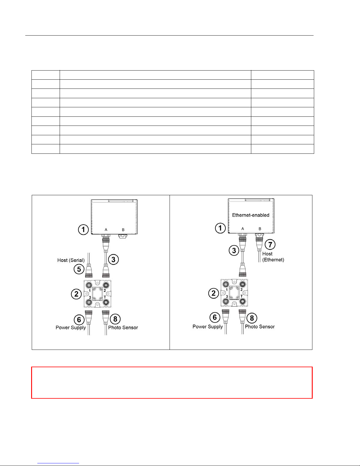
Serial Stan dalo ne (with QX-1)
Ethernet St andalone ( with QX-1)
Step 1 — Check Hardware
Item Description Part Number
1 QX-830 Compact Industrial Scanner FIS-0830-XXXXG
2 QX-1 Interface Device 98-000103-01
3 QX Cordset, Common, M12 12-pin Plug to M12 12-pin Socket, 1 m 61-000162-01
4 QX Cordset, Host, Serial, M12 12-pin Plug to DB9, 1 m 61-000152-01
5 QX Cordset, Host, Serial, M12 12-pin Socket to DB9, 1 m 61-000153-01
6 QX Power Supply, M12 12-pin Socket, 1.3 m 97-000003-01
7 QX Cordset, Host, Ethernet, M12 8-pin Plug to RJ45, 1 m 61-000160-01
8 QX Photo Sensor, M12 4-pin Plug, NPN, Dark On, 2 m 99-000020-02
Note:
Additional cordsets and accessories are available in the Microscan Product Pricing Cat alog.
Note: The QX-830 does not require an Ethernet crossover cordset, because the scanne r
itself performs automatic internal crossover (transmit- to-receive switching). Microscan
offers a standard straight-through (un-crossed) Ethernet cordset (61-000160-01).
1-2 QX-830 Compact Industrial Scanner User’s Manual
Page 13
Quick Start
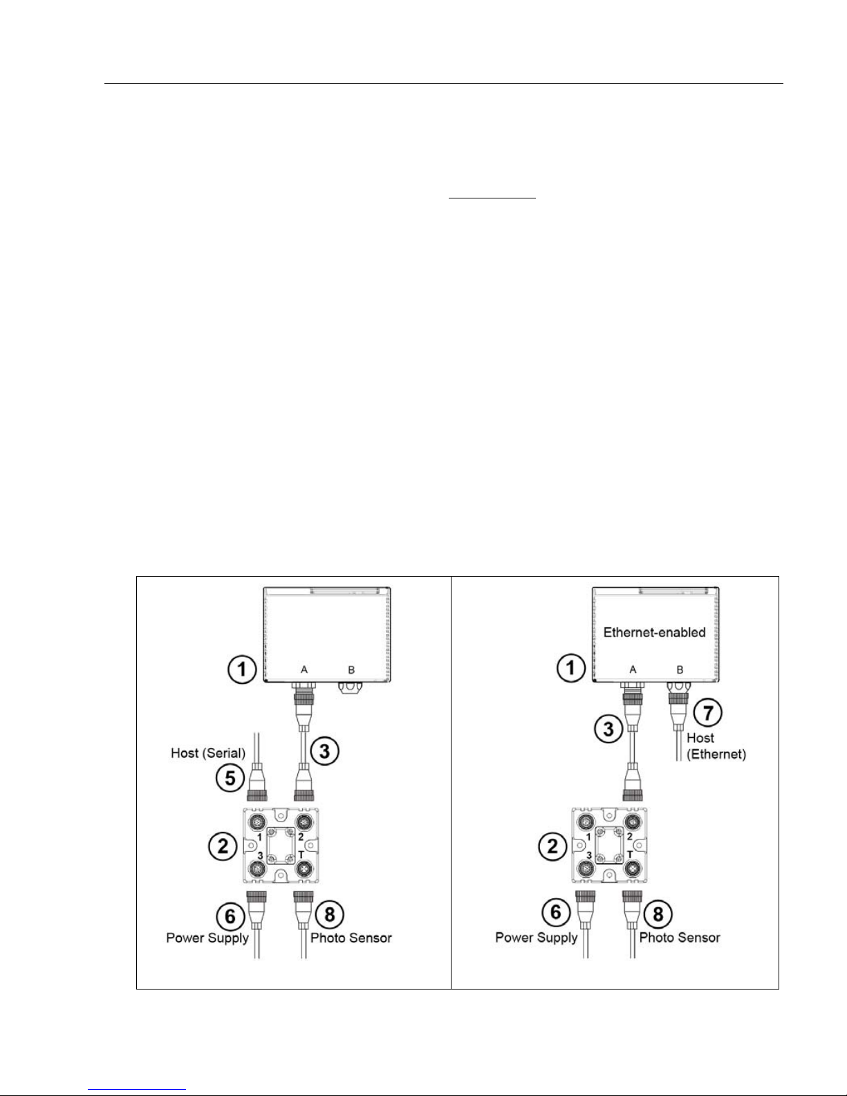
Serial Stan dalo ne (with QX-1)
Ethernet Standalone (with QX-1)
Step 2 — Connect the System
Important: When connectin g Ultra-Lock cordsets to the QX-830 and QX-1, align the pins
first and then push the connector into place. Do not twist
the pins.
RS-232
• Connect the Serial Communication Cable from “A” on the QX-830 to “2” on the QX-1.
• Connect the host cable from “1” on the QX-1 to the host computer.
• Connect the photo sensor to “T” on the QX-1.
• Connect the power supply to “3” on the QX-1.
• Plug in the power supply.
Ethernet
Note: The QX-830 does not require an Ethernet crossover cordset, beca use the scanner
itself performs automatic internal crossover (transmit-to-receive switching). Microscan
offers a standard straight-through (un-crossed) Ethernet cordset (61-000160-01).
• Connect the Ethernet Cable from “B” on the QX-830 to the network.
• Connect the photo sensor to “T” on the QX-1.
• Connect the power supply to “A” on the QX-830.
• Plug in the power supply.
the connectors, as this will bend
QX-830 Compact Industrial Scanner User’s Manu al 1-3
Page 14
Position Scanner and Symbol
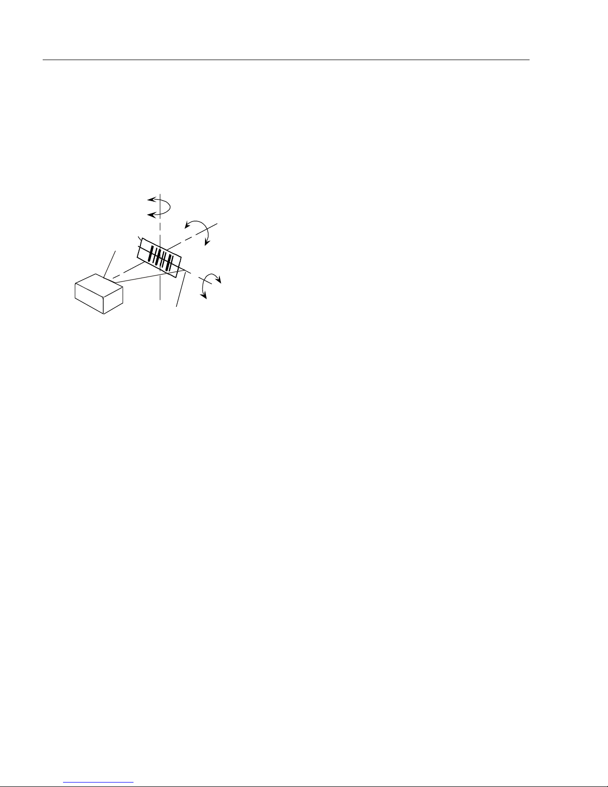
Pitch
axis
Bar code
label
Tilt
axis
axis
Scanline
Scanner
Pitch
Tilt
Skew
Symbol
Scanner
Maximum
skew, tilt,
and pitch:
±30°
Step 3 — Position Scanner and Symbol
• Place a test symbol in a location with as little ambient light as possible.
• Position the scanner at the focal distance used in the application.
• Align the test symbol with the scanner’s field of view.
• Tip the scanner relative to the test symbol to avoid glare from specular reflection.
1-4 QX-830 Compact Industrial Scanner User’s Manual
Page 15

Quick Start
Step 4 — Install ESP
ESP Software can be found on the Microscan Tools CD that is packaged with the QX-830.
1. Follow the prompts to install ESP from the CD.
2. Click on the ESP icon to run the program .
Note: ESP can also be installed from the Download Center at www.microscan.com.
ESP System Requirements
• 166 MHz Pentium processor (recommended)
• Windows Vista, XP, or 2000 operating system
• Internet Explorer 5.0 or higher
• 64 MB minimum RAM
• 50 MB minimum disk space
• 800 x 600 pixel minimum 256 color display
QX-830 Compact Industrial Scanner User’s Manu al 1-5
Page 16
Select Model
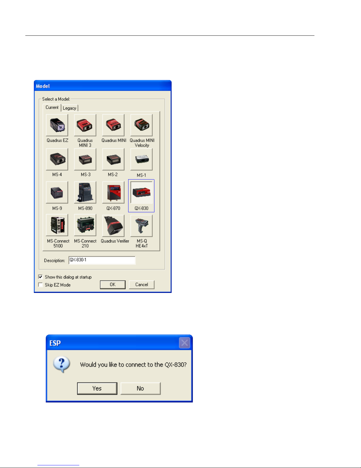
Step 5 — Select Model
When ESP is opened, the following menu will appear:
1. Click the button showing the QX-830.
2. Click OK.
Note:
The QX-830 can also be selected by double-clicking the button showing the QX-830.
3. Click Yes when this dialog appears:
Note: To select another model later , click the Swit ch Model button near the top of the
screen or use Model > New Model in the menu toolbar.
1-6 QX-830 Compact Industrial Scanner User’s Manual
Page 17
Quick Start
RS-232 Connection Wizard
Ethernet Connection Wizard
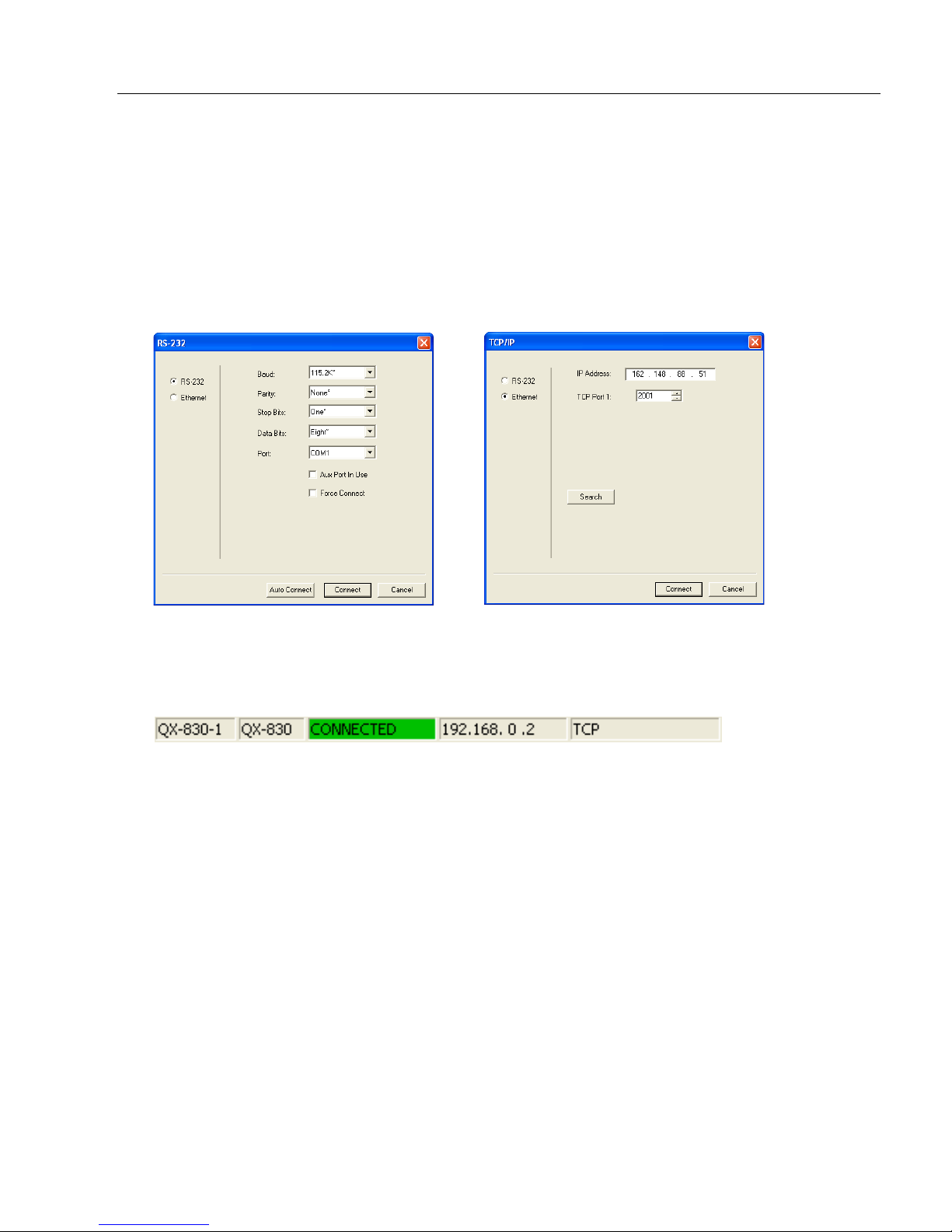
Step 6 — Connect
Connection Wizard
To connect using the Connection Wizard:
• Click Connect on the menu toolbar, and then select Connection Wizard.
•Select RS-232 or Ethernet to activate the appropriate display.
• Configure RS-232 or Ethernet settings as required by the application, and click Connect.
• When a connection is established, the green indicator in the status bar at the bottom
right of the screen will be visible:
Important: The scanner is in Continuous Read Mode by default. For best connection
results, be sure that no decodable symbols are within the scanner’s field of view while
attempting to connect.
QX-830 Compact Industrial Scanner User’s Manu al 1-7
Page 18
Connect (cont.)
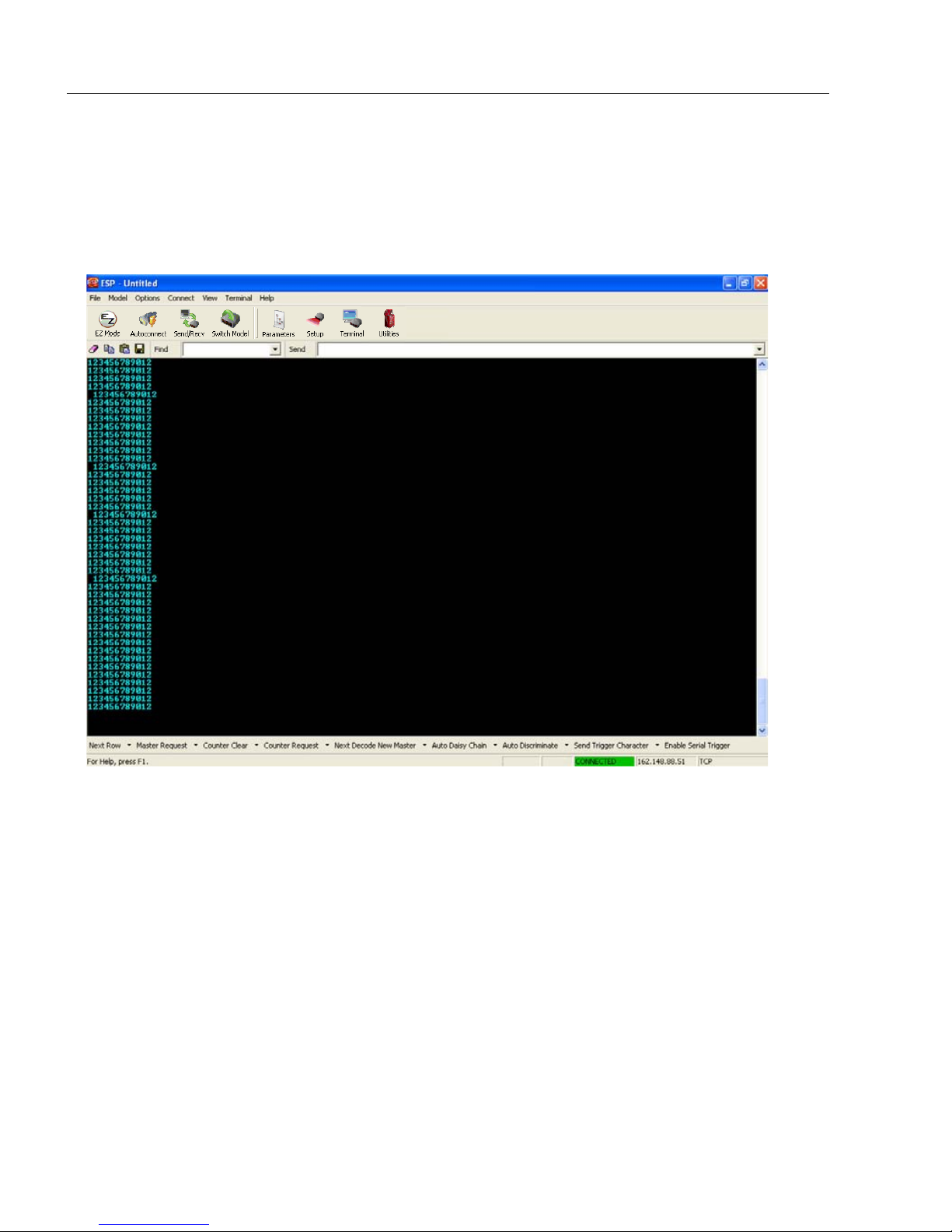
Step 6 — Connect (cont.)
Ethernet TCP/IP
Once the QX-830 is connected, incoming symbol data can be displayed in the Terminal, as
shown below.
1-8 QX-830 Compact Industrial Scanner User’s Manual
Page 19
Quick Start
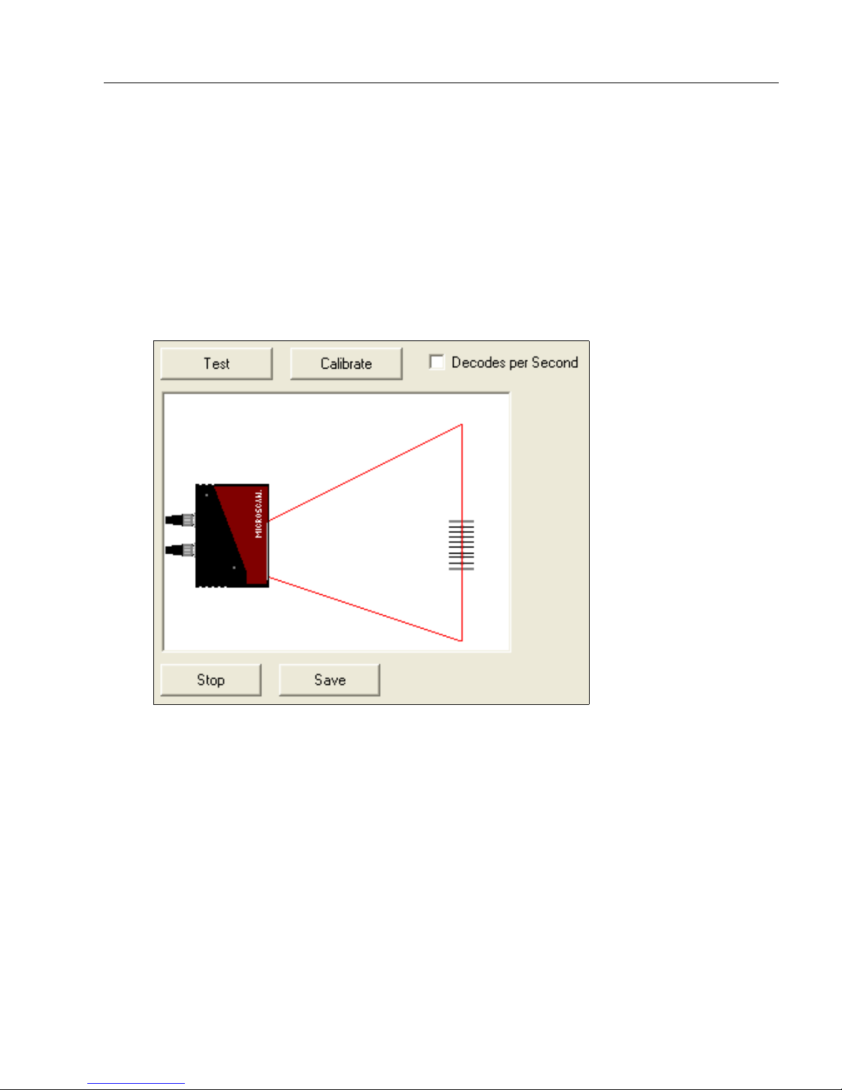
Step 7 — Test Read Rate
Read Rate indicates the number or percentage of successful decodes per second achieved
by the scanner.
1. Click the Test button in ESP’s EZ Mode to start the Read Rate test.
Symbol data and read rate percentage information should appear in the Symbol
Information table in the bottom portion of the view. The Read Rate LEDs on the
side of the QX-830 will indicate the percentage of successful decodes per second.
2. Click Stop to end the Read Rate test.
Note: Read Rate can also be tested using the Read Rate interface in Utilities.
QX-830 Compact Industrial Scanner User’s Manu al 1-9
Page 20
Configure the Scanner
Step 8 — Configure the Scanner
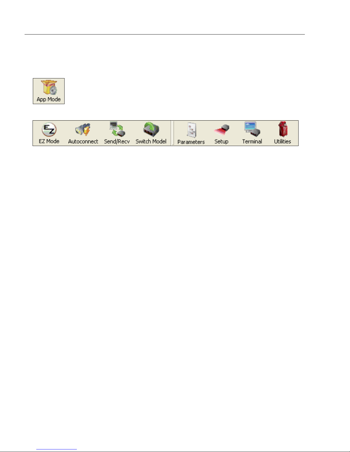
Click the App Mode button to make configuration changes to the scanner.
The following modes are accessible by clicking the buttons at the top of the screen:
• Click the EZ Mode button to return to EZ Mode.
• Click the Autoconnect button to establish communication.
• Click the Send/Recv button to send or receive commands.
• Click the Switch Model button to open the model menu, or to return to a previous model.
• Click the Parameters button to show the tabbed tree control views.
• Click the Setup button to show the tabbed interface views.
• Click the Terminal button to display decoded symbol data and to send serial commands.
• Click the Utilities button to access Read Rate, Counters, Device Control, Differences
from Default, Master Database, Digital Bar Code, and Firmwa re.
For further details, see Microscan ESP Help in the dropdown Help menu.
1-10 QX-830 Compact Industrial Scanner User’s Manual
Page 21
Quick Start
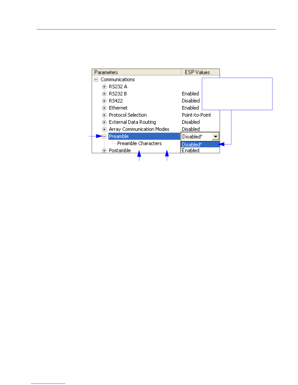
1. Left-click on the +
to expand the
desired tree.
2. Double-click on the
desired parameter
and click once in the
selection box to view
options.
5. Right-click on the open
screen and select Save to
Reader to implement the
command in the scanner.
4. Left-click again
on the open
screen to complete
the selection.
3. Place the cursor in the
selection box, scroll
down to the setting to be
changed, and click once
on the setting.
Step 9 —
Save Changes in ESP
To make changes t o a configuration setting:
Saving Options
• Send, No Save. Changes will be lost when power is re-applied to the scanner.
• Send and Save. This activates all changes in current memory and saves to the scanner
for power-on.
QX-830 Compact Industrial Scanner User’s Manu al 1-11
Page 22

Save Changes in ESP
1-12 QX-830 Compact Industrial Scanner User’s Manual
Page 23

2 Using ESP
EZ Mode........................ ... ............................ ... ............................ ... ...............................................2-2
App Mode............................................. ........................................................ ... ..............................2-3
Menu Toolbar.................................................................................... ............................................2-4
Navigating in ESP............................. ... ............................ ... ............................ .. ..........................2-15
Send/Receive Options ................................................................................................................2-16
Contents
This section explains the basic structure and elements of ESP (Easy Setup Program).
When ESP is opened, unless otherwise specified in ESP Preferences, the EZ Mode view
will appear. App Mode contains several configuration menus (Communication, Read
Cycle, Symbologies, I/O Parameters, Matchcode, and Diagnostics), a Setup interface,
a Terminal interface, and a Utilities interface.
ESP can be used to configure the QX-830 in three different ways:
• Graphic User Interfaces: Scanner settings can be configured using such point-and-click
tools as buttons, spin boxes, check boxes, and drag-and-drop functions.
• T ree Controls: Each conf iguration menu co ntains a list of all option settings th at pertai n
to that specific area of scanner operation. For example, the Read Cycle menu shows a
Laser Setup command, and then a list of the p arameters Laser On/Off, Laser Framing
Status, Laser On Position, Laser Off Position, and Laser Power. Each parameter
can be configured using dropdown menus or fields where characters can be entered.
•
T erminal: ESP
directly to the scanner by typing them in the provided field.
’s
Terminal
allows the user to send serial configuration and utility commands
Information about using specific commands in ESP is provided in subsequent sections.
For ESP system requirements, see ESP System Requirement s in Chapter 1, Quick Start.
QX-830 Compact Industrial Scanner User’s Manu al 2-1
Page 24
EZ Mode
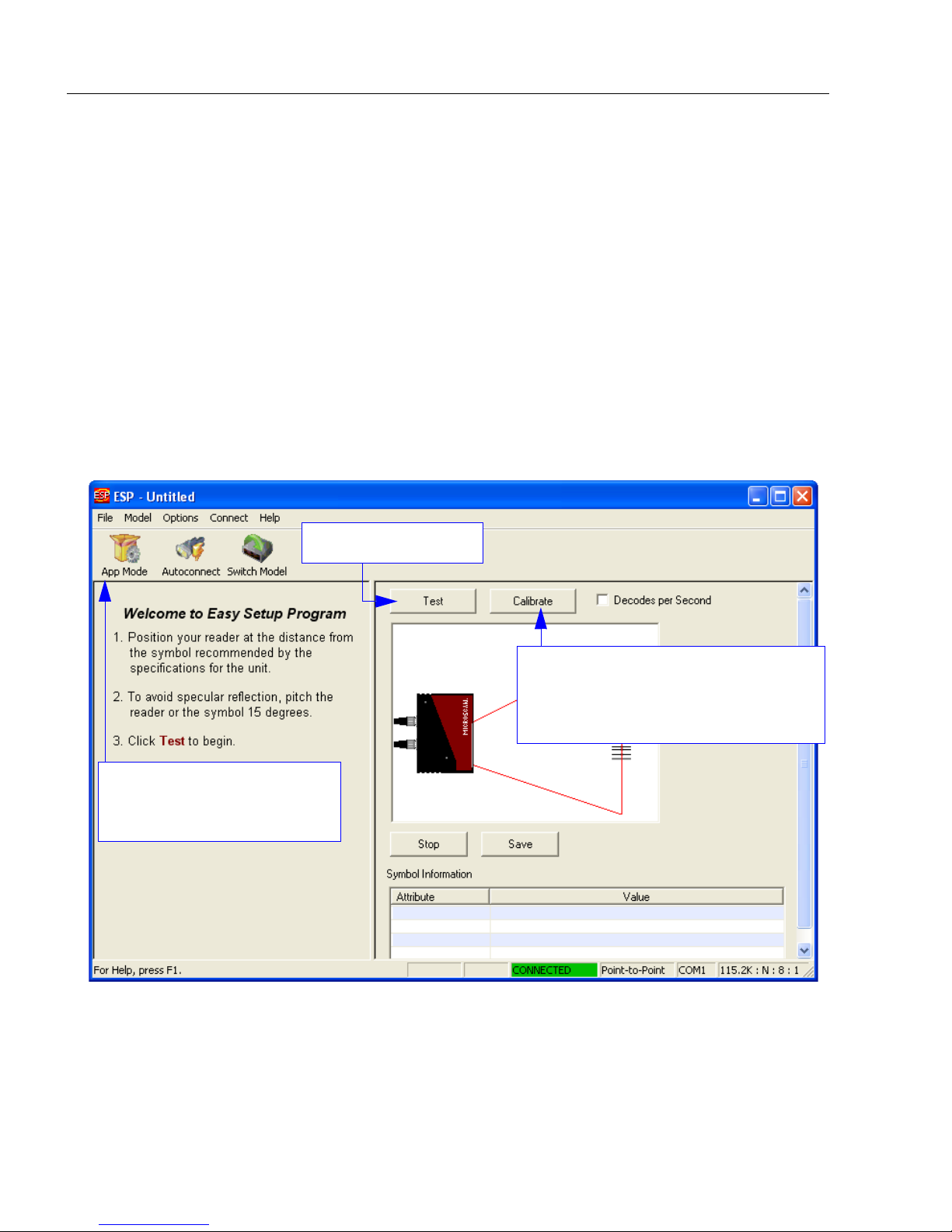
Click the App Mode button
to access configuration trees
and other setup features.
Starts Read Rate test.
Click Calibrate to begin t he calibration
routine. Calibration is explained at the
left of the EZ Mode screen, and also
in Quick Start.
EZ Mode
EZ Mode allows the user to test read rate and calibrate the scanner. After connecting to
the scanner, the EZ Mode view will appear. On-screen instructions assist the user with
positioning, testing, and calibration.
Test
Click the Test button to start the read rate test for a quick indication of the scanner’s read
capabilities and the limits of the application. When Decodes per Second is unchecked,
the test will count the percentage of decodes relative to the number of actual scans. Click
Stop to end the test.
Calibrate
The calibration routine that will optimize the scanner by comparing Read Rates at various
camera and image processing set ting s.
2-2 QX-830 Compact Industrial Scanner User’s Manual
Page 25
Using ESP
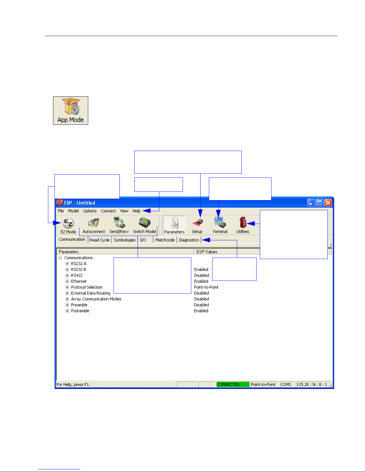
Click here to open
the Terminal view.
Menu toolbar
Click this icon to
return to EZ Mode.
Read Rate,
Counters, Device
Control, Differences
from Default, Master
Database, Digital Bar
Code, Firmware
Tabbed tree
controls
Calibration, Configuration Database,
Ordered Output, Output Format
Autoconnect to the
scanner, Send and
Receive
command settings,
and Switch Model
App Mode
From EZ Mode, click on the App Mode button to access the tabbed tree controls in
Parameters, the intuitive user interfaces in Setup, the Terminal interface, and the Utilities
interface.
Note: The App Mode and EZ Mode buttons appear in the same position to allow easy
switching between these primary modes.
QX-830 Compact Industrial Scanner User’s Manu al 2-3
Page 26
Menu Toolbar
(Save to Scanner)
(Receive Scanner
Settings)
Menu Toolbar
File
New
Whenever New is selected, the default configuration of ESP is
loaded.
Open/Save
When Save or Save As is selected, the ESP configuration is
saved to the host computer’s hard drive and available whenever
the same file is selected under Open.
Important: When configuration changes are saved to the hard
drive, these changes are not automatically saved to the scanner.
The illustration below shows how settings can be saved and
received between ESP and the scanner, and ESP and the host
hard drive.
Import/Export
Import converts the ASCII settings from a text file to ESP configuration settings.
Export converts the active ESP configuration settings to an ASCII text file.
2-4 QX-830 Compact Industrial Scanner User’s Manual
Page 27
Using ESP
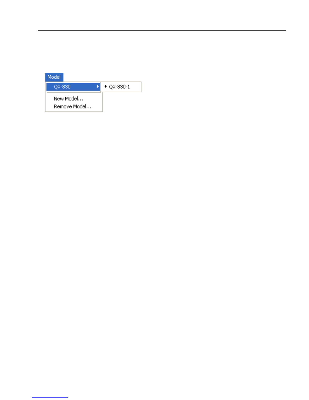
Model
The Model dropdown menu shows a list of recent scanners that have been used with E SP.
When a different model is chosen, the connection to the present model is terminated.
To connect to another model, select New Model, choose a new model from the pop-up
menu that appears, and click OK.
Note: When an ESP file is saved, the settings of all the models defined in that file are saved.
QX-830 Compact Industrial Scanner User’s Manu al 2-5
Page 28
Menu Toolbar
The Toolbar Style
options allow the user
to determine how ESP
will display the mode
options in the two rows
at the top of the screen.
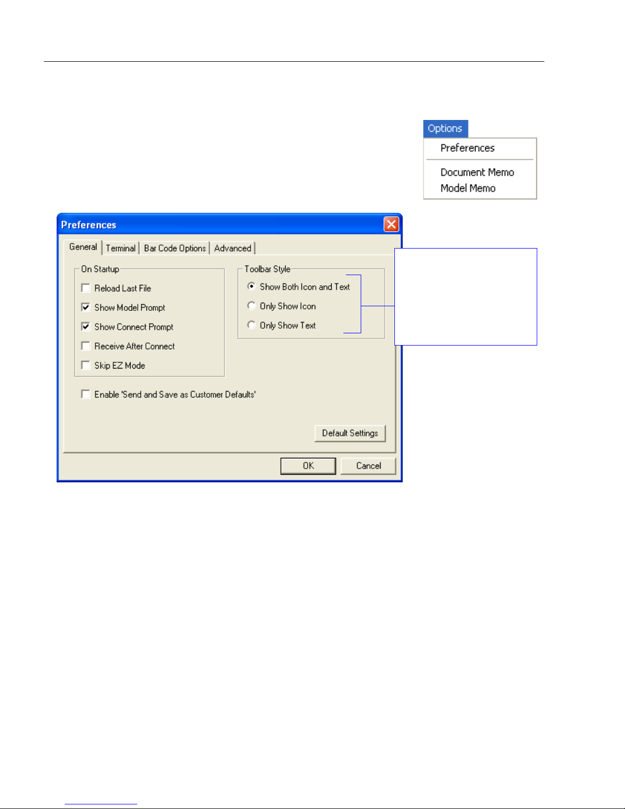
Options
The Options menu allows the user to save memos and set up
ESP Preferences.
Note: Preferences will be saved and loaded into ESP whenever
ESP is opened next, whether or not the ESP file is saved.
Preferences > General Tab
Reload Last File
At startup, reloads the last file saved to the host computer’s hard drive.
Show Model Prompt
At startup, shows the model menu displaying all supported scanners.
Show Connect Prompt
At startup, displays the Would you like to connect to the QX-830? prompt.
Receive After Connect
At startup, loads the scanner’s settings into ESP. (This is not recommended if ESP settings
are needed for future use. )
Skip EZ Mode
At startup, skips EZ Mode and opens directly in App Mode.
Enable ‘Send and Save as Customer Defaults’
At startup, enables the Send and Save as Customer Defaults option in the Send/Recv
command.
2-6 QX-830 Compact Industrial Scanner User’s Manual
Page 29
Using ESP
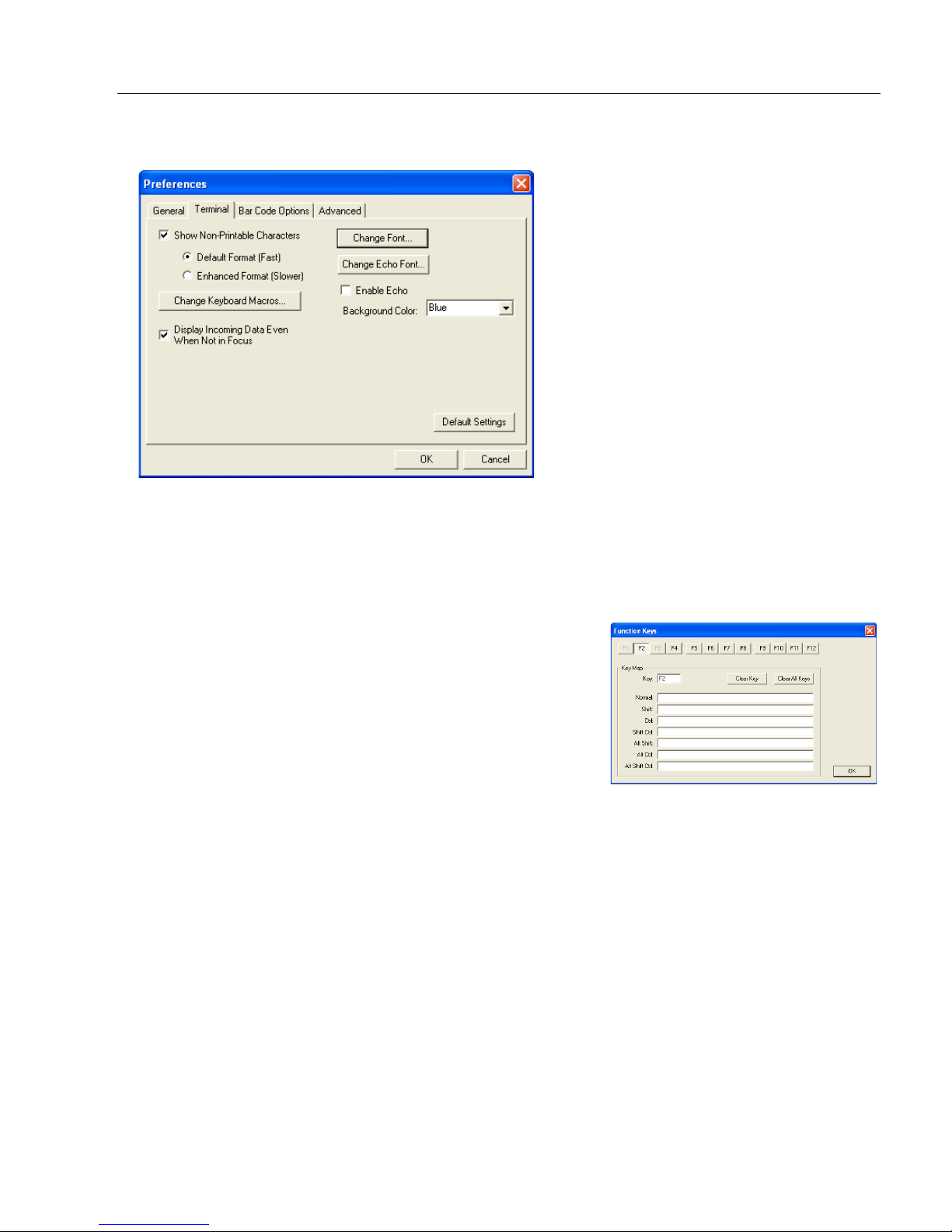
Preferences > Terminal Tab
Show Non-Printable Characters
When Show Non-Printable Characters is enabled, characters such as “CRLF” will be
displayed in the Terminal window. When Enhanced Format is checked, the characters
are displayed with more detailed formatting.
Change Keyboard Macros
Clicking the Change Keyboard Macros button brings
up the Function Keys dialog. In this dialog, select the
desired function key and then enter the macro keystrokes
in the associated key map. For example, to make
the keystroke to send a trigger character, select F2, then
in the Ctrl row , enter <trigger character> and click OK.
Then whenever the Ctrl-F2 keystroke is pressed, the
trigger character will start the read cycle.
Note: The F1 key is reserved for opening ESP Help
and the F3 key is reserved for the Find Next function.
Ctrl-F2
Change Font
Allows the user to modify the font used for de code data rece ived from the scanner on the Terminal.
Change Echo Font
Allows the user to modify the font used for command characters typed into the Terminal.
Enable Echo
Allows the user to enter command characters in Terminal.
Display Incoming Data Even When Not in Focus
When Display Incoming Data Even When Not in Focus is enabled, data from the
scanner will continue to appear in the Terminal even when ESP is not the top window.
QX-830 Compact Industrial Scanner User’s Manu al 2-7
Page 30

Menu Toolbar
Preferences > Bar Code Options Tab
Sizing Information
Sets the bar height (in inches) and bar width (in
symbols.
Example: A bar width of 13 mils is 0.013 inches.
mils
, or thousandths of an inch) of user-created
Caption
Allows the user to define a caption for the symbol, and to determine the alignment of the
caption in relation to the symbol.
2-8 QX-830 Compact Industrial Scanner User’s Manual
Page 31

Preferences > Advanced Tab
Using ESP
The Auto Sync options at the top of the Advanced tab allow the user to determine
whether Auto Sync will be enabled automatically in sections of ESP where it is used, or if it
will ask before it enables Auto Sync functions.
Always Ask Before Auto Sync Occurs
If this option box is checked, specific Auto Sync functions can be enabled.
from the Reader will automatically send the scanner’s settings to ESP when Auto Sync is
enabled.
settings chosen in ESP to the scanner. Do Not Send or Receive Settings creates a
condition in which Auto Sync will not automatically send scanner settings to ESP, or send
ESP settings to the scanner.
Send ESP Settings to the Reader
will automatically send all scanner configuration
Receive Settings
Send XON with Autoconnect
Sends an XON (Begin Transmission) command to the scanner before starting the
Autoconnect routine.
QX-830 Compact Industrial Scanner User’s Manu al 2-9
Page 32

Menu Toolbar
Preferences > Advanced Tab (cont.)
Ask to Save ESP File when Quitting
When enabled, prompts the user to save a .esp file when ending a session.
The .esp file will be saved in the location specified by the user.
Connect to Readers via TCP/IP
When enabled, shows the TCP/IP Connection Wizard by default.
Use Default Storage Location
When enabled, automatically stores data in ESP’s Application Data folder.
2-10 QX-830 Compact Industrial Scanner User’s Manual
Page 33

Using ESP
Document Memo
The information entered in the Document Memo field will appear in a context-sensitive text
box whenever the cursor hovers over the Document Memo item on the Options menu.
Model Memo
Similar to Document Memo, the information entered in the Model Memo field will appear in
a context-sensitive text box whenever the cursor hovers over the Model Memo item on the
Options menu. Memos created in Model Memo are specific to the model enabled when
the message was created.
Note: Memos must be saved in a .esp file to make them available in the next session. If
the current session is not saved, any memos that have been entered during the session
will be discarded, and will be unavailable in the next session.
QX-830 Compact Industrial Scanner User’s Manu al 2-11
Page 34

Menu Toolbar
RS-232 Connection Wizard
Ethernet Connection Wizard
Click the Search
button to locate
scanners on the
network.
Connect
The Connect dropdown men u a llows th e u s er to access th e Connect ion W i zard, as well
as the Autoconnect and Configure Multidrop dialogs. Connect and Disconnect can
also be performed directly from the drop d ow n me n u with ou t op en in g a dia l og .
Connection Wizard
To connect using the Connection Wizard:
• Click Connect on ESP’s menu toolbar, and then select Connection Wizard.
• Select RS-232 or Ethernet to activate the appropriate display.
• Configure RS-232 or Ethernet settings as required by the application, and click Connect.
• When a connection is established, the green indicator in the status bar at the bottom
right of the screen will be visible:
2-12 QX-830 Compact Industrial Scanner User’s Manual
Page 35

Using ESP
• Once the correct
port is chosen,
click Start to
connect.
Autoconnect
•
If the RS-232 connection attempt fails, use
the scanner and the host.
• If the communication port is not the default COM1, use the dropdown menu to change
the port.
Autoconnect
to establish a connection
between
• When a connection is established, the green indicator in the status bar at the bottom
right of the screen will be visible:
QX-830 Compact Industrial Scanner User’s Manu al 2-13
Page 36

Menu Toolbar
Drag specific configuration
values from the control tree
directly into this field to
encode new symbols.
Choose a spatial
orientation for the
new symbol.
Create a caption
for the symbol
that matches or
describes the
encoded data.
The symbol will be
displayed in the field
at the bottom of the
Bar Code Dialog.
View
The View menu allows the user to move quickly between the
Setup, Terminal, and Utilities interfaces without using the icon
buttons on the App Mode toolbar. It also allows the user to
access the Bar Code Dialog, shown below.
Bar Code Dialog
Symbols can be created in the Bar Code Dialog by typing the
text to be encoded. This is a useful tool for creating configuration
symbols, allowing the user to configure the scanner by reading
the user-created symbols.
2-14 QX-830 Compact Industrial Scanner User’s Manual
Page 37

Using ESP
1. Left-click on the + to expand
menu items.
2. Double-click the desired
parameter and single-click
in the selection box to view
options.
3. Place the cursor in the
selection box, scroll down
to the desired setting, and
single-click the setting.
4. Left-click again on the open screen to complete the
selection.
5. Right-click on the open screen and select Save to
Reader to implement the command in the scanner.
The command can be sent without saving, or sent
and saved simultaneously.
The X
indicates
that the
setting is
default.
Navigating in ESP
To change scanner settings, or to access the Setup, Terminal, or Utilities views, click the
App Mode button.
To return to EZ Mode, click the EZ Mode button.
To make changes to configuration settings in the tree controls:
QX-830 Compact Industrial Scanner User’s Manu al 2-15
Page 38

Send/Receive Options
Send/Receive Options
To access Receive, Save, and Default options, click the Send/Recv button. These
options can also be reached by right-clicking in any of the configuration views.
Receiving
From the Send/Recv menu, select Receive Reader Settings.
Caution: Selecting this option will upload the scanner’s settings. If the ESP file has a
number of custom settings that must be maintained and downloaded into the scanner,
these settings will be lost.
This function is useful for receiving (uploading) the scanner’s settin gs and saving the m as
a file for future use. For example, if the scanner has settings that must not change,
Receive Reader Settings would load those settings to ESP and save them in an ESP file
for later retrieval.
Receiving the scanner’s settings will also assure that any unwanted subsequent changes
in ESP will not be saved.
Saving
Send, No Save (<A>)
Saves ESP settings to current
memory.
Send and Save (<Z>)
Activates all changes in current
memory and saves to the scanner
for power-on.
Send and Save as Customer Defaults (<Zc>)
Saves default settings for quick retrieval.
This option will be visible only if Enable ‘Send and Save as Customer Defaults’ is
checked in ESP Preferences.
2-16 QX-830 Compact Industrial Scanner User’s Manual
Page 39

Using ESP
Defaulting
When Default Curren t Menu Settings or Default all ESP Settings are selected, only the
ESP settings are defaulted.
Advanced Options
Send Current View
This is the same as
>
Send No Save
commands in the current configuration
tree are sent.
Save to Reader
except that only the
Send Current Command
This is the same as
View
, except that it saves only the
command that is currently selected.
Send Current
Add/Remove Exception
After a Receive Reader Settings command is performed1 and the Add Exception option
is selected, a list of serial commands may appear. These are commands that may be in
the scanner’s firmware, but are not included in, or are different from, the current version of
These commands can be edited by double-clicking them and changing them as needed.
It is important to note that these commands will be saved to the scanner whenever a Save
to Reader command is sent, or when an <A> or a <Z> command is sent.
Also, if there is a corresponding ESP menu item, the ESP Value column for that item will
be blank following a Receive Reader Settings command.
ESP
.
1. From the Send/Recv button or by right-clicking in any b l a nk sect ion o f a tree co ntrol view.
QX-830 Compact Industrial Scanner User’s Manu al 2-17
Page 40

Send/Receive Options
2-18 QX-830 Compact Industrial Scanner User’s Manual
Page 41

3 Hardware Integration
Connectors ...................................................................................................................................3-2
Cordsets .......................................................................................................................................3-3
QX-830 and QX-1 Connectors and Pinouts..................................................................................3-4
Power and Trigger Switching........................................................................................................3-8
Port Routing........................................................... .. ...................................................... ...............3-9
Application Examples .............................................. ... ... .................................. .. .........................3-10
Contents
This section introduces the details of QX-830 hardware, and explains how that hardware
can be integrated in an application.
QX-830 Compact Industrial Scanner User’s Manu al 3-1
Page 42

Connectors
Ultra-Lock connectors are more resistant to harsh industrial
conditions, and are easy to connect.
QX-830 with M12 Ultra-Lock
Connector
Ultra-Lock Connector
Traditional Threaded Connectors
Connectors
Industrial cabling and connectivity schemes must be able to withstand environmental
extremes of heat, cold, and moisture, and be secure enough not to be disconnected or
damaged inadvertently in the course of day-to-day operation.
The current industry standard for connectivity is a sealed, circular connector such as the
M12. The International Electrotechnical Commission (IEC) st andard for M12 connectors
describes them as fixed
available off-the-shelf from manufacturers
Molex, or Binder.
The QX-830
uses sealed, circular connectors
and free screw-locking connectors. This type of connector is widely
such as Turck, Lumberg, Phoenix Contact,
with Ultra-Lock™ technology.
Ultra-Lock Connectors
Microscan has adopted Ultra-Lock connectivity because of speed, ease-of-use, and
ingress protection considerations. The main advantage of the Ultra-Lock system is that
only two steps are required at every connection poin t:
1. Align the conn ector and re ceptacle keys;
2. Push the connector into place. (Do not twist the connector, as this can bend the pins.)
Ultra-Lock connectors are “operator-independe nt”. This means that they are not subject to
under-tightening or over-tighten ing, both of which are common problems with screw-down
connectors, and both of which undermine the moisture-resistant seal.
Another advantage of the QX-830’s Ultra-Lock connectivity scheme is that the Ultra-Lock
receptacles on the scanners and the QX-1 Interface Device also accept screw-down
connectors, giving users the flexibility to use either Ultra-Lock or screw-down connectors.
“Ultra-Lock” is a trademark of Woodhead (Molex).
3-2 QX-830 Compact Industrial Scanner User’s Manual
Page 43

Hardware Installation
M12 Ultra-Lock to RJ45 (Ethernet) Cordset
M12 Ultra-Lock to M12 Ultra-Lock Cordset
M12 Ultra-Lock to Photo Sensor Cordset
Cable with flying leads
Cordsets
The terms “cordset” and “cable” are both applicable to industrial connectivity, but they are
not synonymous. Cordsets enable communications and power between scanners and
interface devices. Cordsets have an M12 Ultra-Lock connector at one or both ends.
Examples of cordsets are shown below.
Cables do not have M12 Ultra-Lock connectors at either end. An example of a cable is
shown below.
QX-830 Compact Industrial Scanner User’s Manu al 3-3
Page 44

QX-830 and QX-1 Connectors and Pinouts
Connector B is a 12-pin socket on
RS-232 scanner models, and an
8-pin socket on Ethernet models.
Connector A on the back of the QX-830 is a
12-pin plug on both Serial and Ethernet models.
QX-830 Connectors
Important: The 8-pin Ethernet
version of Connector B does
not have RS-422/485, Input 1,
or RTS/CTS pins.
Ground
Output 3
Output 1
Output 2
New Master
Default
Power
Input Common
Output Common
RS-232 RxD
Trigger
RS-232
TxD
Connector A (Serial) M12 12-pin Plug
Input
Common
RS-422/485 RxD (–)
RS-232 TxD/RS-232 RTS
Trigger
RS-232 RxD/RS-232 CTS
Power
Ground
RS-422/485
RxD (+)
RS-422/485
TxD (+)
RS-422/485 TxD (–)
Input 1
Terminated
Connector B (Serial) M12 12-pin Socket
TX (+)
RX (–)
RX (+)
TX (–)
Terminated
Terminated
Connector B (Ethernet) M12 8-pin Socket
Terminated
Terminated
QX-830 and QX-1 Connectors and Pinouts
When deploying a network of scanners and interface devices in an industrial setting, it is
important to use component s whose pin assignments are arranged in a way that avoids
communication errors and equipment damage. This can be achieved with components
that are designed in a logical, consistent, and easy-to-implement way.
The QX-830 has a very simple pin assignment methodology . The clearly identified connectors
at the back of the unit can be used to rece ive and bus power, and also to send and receive
data and commands.
QX-830 Connector Pin Assignments
3-4 QX-830 Compact Industrial Scanner User’s Manual
Page 45

Hardware Installation
An earth ground is provided through the cable shields and chassis of the scanner.
Grounding the QX-830
Proper grounding is necessary for operator safety, noise reduction, and the protection of
equipment from voltage transients. Buildings, including any steelwork, all circuits, and all
junction boxes must be grounded directly to an earth ground in compliance with local and
national electrical codes.
Ground Loops
Ground loops (signal degradation due to different ground potentials in communicating
devices) can be eliminated or minimized by ensuring that both th e host, scanner, and their
power supplies are connected to a common earth ground.
QX-830 Compact Industrial Scanner User’s Manu al 3-5
Page 46

QX-830 and QX-1 Connectors and Pinouts
Expected Power and Ground Connections for Proper Operation
Notes:
• Ensure that mounting bracket “Earth” is at the same potential as power source “Earth”.
• Supply “Return” and “Earth” ground must be stable, low-impedance reference points.
• “2-Terminal Power Supply” must still provide an “Earth” connection to the scanner.
• “Signal Ground” can be used for communications and/or discrete signal ground reference.
It must not be used as Power Ground or Earth Ground.
3-6 QX-830 Compact Industrial Scanner User’s Manual
Page 47

Hardware Installation
Connectors 1 and 3 are 12-pin plugs, and Connector 2 is a 12-pin socket.
All three connectors can be assigned to bus power and data as required by
the application.
The two switches at the center of the device allow the user to route signals
as needed.
Pin Assignment
1 + 10-28V
2
Trig/NM/Input 1
Common
3 Ground
4 Trigger
QX-1 Interface Device
QX-1 Trigger Connector 4-pin Socket
PWR
TRIG
1, 3,
T
1, 2,
3, T
1, 2,
3
1, 3
This simple diagram (shown on the base of the QX-1) illustrates how
power, communications, I/O, and trigger signal can be routed through
the QX-1 device depending on the needs of the application. The
switches greatly increase signal routing flexibility.
QX-1 Communications - I/O -
Power - Trigger
QX-1 Interface Device
The QX-1 Interface Device’s receptacles are physically the same as those on the QX-830,
but they do not have explicit pin assignments. The QX-1 allows users to bus power and
communications as required by the application.
QX-830 Compact Industrial Scanner User’s Manu al 3-7
Page 48

Power and Trigger Switching
PWR
TRIG
1, 3,
T
1, 2,
3, T
1, 2,
3
1, 3
Power can be bussed between scanners and interface
devices. At each location on a network where a new power
supply is added, the Power switch on the QX-1 can be
used to break power between Connector 2 and Connector s
1, 3, and T.
The Trigger signal between Connector 2 and Connectors
1, 3, and T can be broken using the Trigger switch. This
isolates trigger signals as required by the application.
Power and Trigger Switching
3-8 QX-830 Compact Industrial Scanner User’s Manual
Page 49

Hardware Installation
RS-232 A, RS-232 B, and RS-422 are
serial. RS-232 A is always enabled. RS-232
B and RS-422 can be enabled or disabled to
match the physical requirements of the
application. Ethernet can also be enabled
or disabled as required.
RS-232 A, RS-232 B, and RS-422 can be
configured for Baud Rate, Parity, Stop Bits,
Data Bits, Symbol Data Output, Extra Symbol
Information (Decodes Before Output, Symbol
Position Output, etc.), Diagnostics Output,
and External Source Processing Mode
(Command or Data).
Ethernet can be configured for IP Address,
Subnet Mask, Gateway, IP Address Mode
(Primary or Secondary TCP Port), Symbol
Data Output, Extra Symbol Information,
Diagnostics Output, and External Source
Processing Mode.
Port Routing
The physical advantages create d by flexible signal routing and switching are enhanced
further by Port Routing, which can be configured in ESP. Port Routing eliminates the
need for dedicated “Host” and “Aux” ports in a traditional sense. With Port Routing, any
port can be defined as a Host or Aux port. Port Routing also allows users to define the
data types that are accessible from specific ports.
The primary benefit of Port Routing is that any type of data can be routed to any port, and
can be sent through multiple ports simultaneously. Multiple types of data can also be
appended to the symbol data that is output from the scanner to the host. Command data,
symbol data, extra symbol information, and diagnostic data are enabled by default in the QX-830.
The table below lists different types of data, with examples for each data type.
Data Type Example
Command Data Serial commands; scanner responses to serial commands.
Symbol Data Any string of data encoded in a symbol.
Extra Symbol Information Decodes per trigger, decode direction, configuration database index number.
Diagnostic Data Laser status, temperature, service message.
The screen capture below (from ESP) shows the QX-830’s four communi cations ports and
the parameters for each.
QX-830 Compact Industrial Scanner User’s Manu al 3-9
Page 50

Application Examples
Application Examples
The following examples demonstrate how the components described in previous pages
can be deployed in industrial applications.
Daisy Chain
Daisy chain configurations are used in applications such as product packaging, where
single items have multiple symbols. For example, a box with one symbol on the top and
symbols on either side requires at least three scanners to ensure that all symbols will be
decoded.
The highlighted areas below demonstrate how a daisy chain can be arranged. One scanner
is placed above the conveyor line and one scanner is p laced on each side of the line. The
three scanners essentially function as a single scanner, and data is sent from the primary
scanner to the host or PLC.
3-10 QX-830 Compact Industrial Scanner User’s Manual
Page 51

Hardware Installation
Multidrop
Multidrop networks are used in applications where it is necessary to decode symbols at
multiple locations within an industrial process. Scanner s are placed at stations located
between manufacturing steps, and data from those scanners is directed to a multidrop
concentrator before being sent to a host. An example of this type of application is food
packaging, in which part number dat a is collected and tr acked throu ghout the packaging
process.
The highlighted areas below demonstrate how a multidrop network can be arranged.
QX-830 Compact Industrial Scanner User’s Manu al 3-11
Page 52

Application Examples
Ethernet TCP/IP and EtherNet/IP
Ethernet TCP/IP is the standard Ethernet interface used to connect multiple locations in a
network, such as computers in an office network. It can also be used to network other
communications devices, such as scanners and PLCs on a factory floor.
EtherNet/IP™ is a protocol developed and governed by ODVA (Open DeviceNet V endor s
Associ a tion). It is based on the Common Industrial Protocol (CIP™). The CIP layer is an
additional layer within the standard Ethernet interface (Ethernet TCP/IP). EtherNet/IP is
common in control systems and PLCs, especially in the United States.
The highlighted areas below demonstrate how an Ethernet daisy chain can be arranged.
Ethernet-enabled scan ners can also be set up in stand a lone configurations, or mult iple
Ethernet-enabled scanners along a production or packaging line can be connected to Ethernet.
“EtherNet/IP” and “CIP” are trademarks of the Open DeviceNet Vendors Association.
3-12 QX-830 Compact Industrial Scanner User’s Manual
Page 53

4 Scanner Setup
Calibration.....................................................................................................................................4-2
Configuration Database..................... ... ... ................................. ... .................................. .. .............4-4
Ordered Output.............................................................................................................................4-6
Output Format.......................................................... ... ................................................................4-10
Contents
This section describes ESP’s four Setup interfaces: Calibration, Configuration Dat abase,
Ordered Output, and Output Format. Each inte rface allows the user to make changes to
scanner configuration quickly and easily.
QX-830 Compact Industrial Scanner User’s Manu al 4-1
Page 54

Calibration
Click the Setup button and then the Calibration tab
to display the Calibration view.
The Test and Calibrate features
are also available in EZ Mode.
Scan Speed, Gain,
and Tracking can
also be configured
in the Reader
Setup command.
Click Save to save calibration
settings, or Stop to cancel the
calibration process.
Laser Off Position
and Laser On Position
can be entered using
the fields below, or by
clicking and dragging
the edges of the laser
arc in the picture.
Calibration
The settings in the Calibration interface can also be configured using the <@> and
<@CAL> serial commands, and the Calibration Options command.
4-2 QX-830 Compact Industrial Scanner User’s Manual
Page 55

Scanner Setup
Laser Off Position
Laser On Position
Laser Off Position
Percentage of the full scan arc that the scan beam moves through before the laser tur ns off.
The combined values of Laser On Position and Laser Off Position cannot exceed 100
percent, the total arc of one scan.
Laser Off Position must always exceed the value of Laser On Position for a scan to
take place.
Laser On Position
Percentage of the full scan arc that the scan beam moves through before the laser turns
on. For example, if set to 30, the laser will be off during the first 30 percent of the scan.
When Laser Framing is disabled, the laser is on for 100 percent of the full scan.
QX-830 Compact Industrial Scanner User’s Manu al 4-3
Page 56

Configuration Database
Click the Setup button and then the Configuration Dat abase tab
to display the Configuration Database vie w.
Double-clicking on an
Index will bring up the
Configuration Database
Settings dialog.
Use the Number of Active
Indexes field to determine how
many database indexes will be used.
Use the Number of Database
Cycles to determine how many
times the active indexes will be
repeated.
Use the Switch Timing field to
determine the amount of time
between active indexes.
Configuration Database
Configuration Database settings can also be configured by using the Configuration
Database serial commands.
4-4 QX-830 Compact Industrial Scanner User’s Manual
Page 57

Scanner Setup
The settings shown above can be
configured differently for every active
index. Once all active database
indexes are configured, the index can
be concatenated and cycled for the
number of times specified in Number
of Database Cycles.
Configuration Database Settings
Double-clicking an Index will bring up the Configuration Database Settings dialog for
that database index.
QX-830 Compact Industrial Scanner User’s Manu al 4-5
Page 58

Ordered Output
Click the Setup button and then the Ordered Output tab
to display the Ordered Output view.
Number of Filters refers to the number of active output
filters. 0 disables all output filters. Any non-zero numeral
will enable output filtering to be performed using the filter
indexes covered by this value.
For example, if the number of filters is 5, then filter
indexes 1, 2, 3, 4, and 5 will be applied.
Filter Number, Symbology Type, Length, Wildcard, Placeholder, and Matching Data are all
displayed in the table below. Double-clicking on any row of the table will display the Ordered
Output Filter Settings dialog, where settings can be changed.
Receive settings from the scanner, Send settings
to the scanner, or Send and Save settings.
Ordered Output
Output filtering is a method of providing a set of good read qualifiers and also providing
ordered output. There is a filter for up to the first 10 positions in a multisymbol output. The
first filter corresponds to the first symbol output at
settings for the following six parameters: Filter Number, Symbology Type, Length,
Wildcard, Placeholder, and Matching Data.
the end of the read cycle. Each filter has
4-6 QX-830 Compact Industrial Scanner User’s Manual
Page 59

Scanner Setup
Filter Number
This is the filter index number that represents the positio n of the symbol in th e dat a output
at the end of the read cycle. This index number should be ente red along with the following
filter settings for the predetermined symbol position.
Symbology Type
Specifies the symbology type allowed to occupy this location in multisymbol output.
Note: To filter or order a symbol, the symbol must meet all the requirements of the
selected filter index.
Length
Spec ifies the length of the decoded symbol allowed to occupy this location in multisymbol
output.
Note: To filter or order a symbol, the symbol must meet all requirements of the selected
filter index.
Wildcard
This is the character to be used in the data output field when performing a data filter
comparison. The wildcard character represents the end of matching, and allows for variable
lengths of symbol output.
Placeholder
The placeholder character requires a character to be present, but does not compare the
data value.
Matching Data
This is the data string to be used when comparin g symbol data for output filtering and
ordering. This data string may also contain wildcard and placeholder characters to facilitate
matching. Remember that in order to filter or order symbol data, it must meet all the
requirements of the selected filter index.
Examples:
• Filter data = “123*”. This will match data strings of “123”, “123456”, and “123ABC”, but
not “12”.
• Filter data = “123*AB?C”. This will be interpreted as “123*”.
• Filter data = “123?”. This will match “1234” and “123A”, but not “123”, “12345”, or
“1234C”.
• Filter data = “123?A”. This will match “1234A” and “123BA”, but not “123”, “1234C”, or
“1234ABCD”.
• Filter data = “123?A?”. This will match “1234AB” and “123BAT”, but not “1234A” or
“123BATS”.
• Filter data = “12??*”. This will match “1234”, “123456”, and “123ABC”, but not “12” or
“123”.
• Filter data = “123?A*”. This will match “1234A”, “123BA”, and “123BA TS”, but no t “1234”
or “1234C”.
QX-830 Compact Industrial Scanner User’s Manu al 4-7
Page 60

Ordered Output
Double-clicking on a row in the
Ordered Output table brings up the
Ordered Output Filter Settings
dialog.
Use these settings to determine
Symbology Type, Length of the
symbol, a user-defined Matching
String, ASCII Lookup, Wildcard
Character, and Placeholder
Character. Click Apply to save the
settings to the corresponding filter.
Ordered Output Filter Settings
4-8 QX-830 Compact Industrial Scanner User’s Manual
Page 61

Scanner Setup
Rules for Output Filter Configuration
Output Filter Configuration Rule # 1
Each symbol that is decoded must match one of the filters before it can be saved to a read
cycle record. There is an exception to this rule, however, when the number of symbols
required for a read cycle exceeds the number of active filters. In such a case, unfiltered
symbols can be placed into unfiltered output positions.
For example, if the number of symbols required is 6 but there are only 5 active filters, the
last position can be filled by any (unfiltered) qualified symbol.
Output Filter Configuration Rule # 2
The same filter setup can be used multiple times.
For example, filters 1, 2, and 3 can be set up to filter Code 39 symbols, and the output will
occur in the order the symbols are decoded.
Output Filter Configuration Rule # 3
All qualified symbols will be sorted and output in the matching filter position. If a symbol
matches filter 3, it will be output as the third symbol. If a filter does not have a matching
qualified symbol, a No Read message will be output in place of the symbol (assuming the
No Read message is enabled).
For example, if there is not a symbol that meets filter 3’s requirements, then a No Read
message will be output in the third output position.
QX-830 Compact Industrial Scanner User’s Manu al 4-9
Page 62

Output Format
Click the Setup button and then the Output Format tab
to display the Output Format view.
On the Output Format tab, check the Enable Output Format box.
Output Format
Enable Output Format
This is a global enable/disable parameter. Use Set Number of Symbols and Output
Phrase to assign symbols for formatting, and Symbol Parse to determine the specific
output content for the assigned symbols.
4-10 QX-830 Compact Industrial Scanner User’s Manual
Page 63

Set Number of Symbols
Check the
Parse boxes
beneath the
symbols to
be formatted.
Use the Set Number of Symbols spin box to
determine the number of symbols to be included
in the output phrase.
Enter Postamble characters by
double-clicking in the text field and
then using the Postamble calculator.
Enter Postamble characters by
double-clicking in the text field and
then using the Postamble calculator .
Scanner Setup
Number of Symbols
determines the number of symbols to which output formatting will apply .
Output Phrase
Output Phrase refers to the user-defined Preamble, selected symbols, and Postamble
sequence in the read cycle result.
QX-830 Compact Industrial Scanner User’s Manu al 4-11
Page 64

Output Format
Multiple character sequences can be extracted and inserted using Symbol Parse. In this example,
the selected extraction range is characters 2-4. The “Sample Symbol” example on the Symbol
Parse
dialog shows the selected character positions extracted and output as desired. Simultaneously ,
the data string from the selected symbol is displayed at the bottom left of the Parse Table, followed
by the user-defined extracted output.
The Extract Range
function corresponds to
the Start Location and
Length parameters in
the Format Extract
serial command.
Symbol Parse
Extract
Output Index
Output Index
output is built by extracting data from a symbol’s original data output and/or inserting
user-defined characters.
It may be helpful to think of individual indexes as positions in the final for matted output.
Starting with index # 1, enter either an extract or insert command to begin building the
desired output string. Then, with the next index number, enter either an extract or insert
command to continue building the output string. Continue this process until the string is
built.
refers to the database entry to be modified with this command.
A formatted
Start Location
Defines the location within the symbol data where the character extraction will begin. The
first character extracted will also be the first character in the sequence displayed in user-defined
output.
Length
Defines the length (in consecutive characters) that will be extracted and placed in user-defined
output.
4-12 QX-830 Compact Industrial Scanner User’s Manual
Page 65

Insert
The Insert process is very similar to the
Extract process, except that Insert
allows the user to enter characters using
the Insert calculator (shown above).
Notice that Extract
and Insert share the
same Parse Table.
Scanner Setup
QX-830 Compact Industrial Scanner User’s Manu al 4-13
Page 66

Output Format
4-14 QX-830 Compact Industrial Scanner User’s Manual
Page 67

5 Scanner Parameters
Communication.............................................................................................................................5-2
Read Cycle ................................................... ... ............................ ... ............................................5-43
Symbologies ...............................................................................................................................5-70
I/O Parameters............... ... ............................ ... ............................ ... ..........................................5-107
Matchcode ................................................................................................................................5-168
Diagnostics ...............................................................................................................................5-177
Contents
This section explains the function and purpose of the Parameters commands in ESP’s
tabbed tree controls.
Important: Unless otherwise specified, command settings shown in this section are the
default settings.
QX-830 Compact Industrial Scanner User’s Manu al 5-1
Page 68

Communication
Click the App Mode button and then the Parameters button to display the
tree control tabs.
Then click the Communication tab to display the Communication tree control.
To open nested options,
single-click the +.
T o change a setting, double-click the
setting and use the cursor to scroll
through the options.
The * indicates
that the setting
is the default.
Communication
Note: Communication settings can also be sent to the scanner from ESP’s Terminal using
Microscan’s K command format. Refer to the Communication section of Appendix D.
5-2 QX-830 Compact Industrial Scanner User’s Manual
Page 69

Scanner Parameters
Port Routing
The QX-830 features a communication system based on Port Routing instead of traditional,
dedicated serial ports. Decisions can be made about the direction and content of communication
between ports based on different Data Types. Any available port can be used in any
combination.
The fundamental concept of Port Routing is that communication design can be based
upon Data Types rather than ports. The advant age of this is the ability to map different
data types to different ports—the user is no longer limited to a “Host Port” and “Aux Port”
for specific types of input and output. Since each port is independent instead of fixed for a
particular purpose, the scanne r behaves more like a data switch.
Port Routing Advantages
• Data can be routed in on one port and out on the same port or a different port like a
switch or router. Transparent Mode, Half Duplex Mode, Full Duplex Mode, and
Custom Mode.
• External Data Routing still follows the “To/From Host/Aux” paradigm. The new capability
allows the customer to define the data direction—which port behaves as the “Host Port”
and which port behaves as the “Aux Port”.
• Only one daisy chain setup required per system.
• Minimal configuration required for each port, with similar items grouped together.
QX-830 Compact Industrial Scanner User’s Manu al 5-3
Page 70

Communication
RS-232 A
The following settings define the basic transmission speeds and digital standards that
ensure common RS-232 formatting.
Baud Rate
Can be used to transfer data faster or to match host port settings.
The rate at which the scanner and host transfer data back and forth.
Parity
Only changed if necessary to match host setting.
An error detection routine in which one data bit per character is set to 1 or 0 so that the
total number of bits in the data field is either even or odd.
Stop Bits
Only changed if necessary to match host setting.
One or two bits added to the end of each character to indicate the end of the character.
5-4 QX-830 Compact Industrial Scanner User’s Manual
Page 71

Scanner Parameters
Data Bits
Only changed if necessary to match host setting.
One or two bits added to the end of each character to indicate the end of the character.
Symbol Data Output
Enables or disables decoded symbol data output from the scanner.
Extra Symbol Information
Enables or disables extra symbol information output from the scanner.
Diagnostics Output
Enables or disables diagnostics output from the scanner.
QX-830 Compact Industrial Scanner User’s Manu al 5-5
Page 72

Communication
External Source Processing Mode
Enables or disables processing of commands or data from sources external to the scanner.
Command
Command enables command processing in the scanner.
Note: Command processing is always enabled for RS-232 A.
Data
Data enables RS-232 A as a data source port.
Note: The data path between in the source port and out the source port is always two-way.
Data is copied from source dat a port s and all those source port s’ dat a is transmitted to th e
destination port, and from the destination port to the source port.
5-6 QX-830 Compact Industrial Scanner User’s Manual
Page 73

Scanner Parameters
RS-232 B
The following settings define the basic transmission speeds and digital standards that
ensure common RS-232 formatting.
Baud Rate
Can be used to transfer data faster or to match host port settings.
The rate at which the scanner and host transfer data back and forth.
Parity
Only changed if necessary to match host setting.
An error detection routine in which one data bit per character is set to 1 or 0 so that the
total number of bits in the data field is either even or odd.
Stop Bits
Only changed if necessary to match host setting.
One or two bits added to the end of each character to indicate the end of the character.
QX-830 Compact Industrial Scanner User’s Manu al 5-7
Page 74

Communication
Data Bits
Only changed if necessary to match host setting.
One or two bits added to the end of each character to indicate the end of the character.
Symbol Data Output
Enables or disables decoded symbol data output from the scanner.
Extra Symbol Information
Enables or disables extra symbol information output from the scanner.
Diagnostics Output
Enables or disables diagnostics output from the scanner.
5-8 QX-830 Compact Industrial Scanner User’s Manual
Page 75

Scanner Parameters
External Source Processing Mode
Enables or disables processing of commands or data from sources external to the scanner .
Command
Command enables command processing in the scanner.
Data
Data enables RS-232 B as a data source port.
Note: The data path between in the source port and out the source port is always two-way.
Data is copied from source dat a port s and all those source port s’ dat a is transmitted to the
destination port, and from the destination port to the source port.
QX-830 Compact Industrial Scanner User’s Manu al 5-9
Page 76

Communication
RS-422
The following settings define the basic transmission speeds and digital standards that
ensure common RS-422 formatting.
Baud Rate
Can be used to transfer data faster or to match host port settings.
The rate at which the scanner and host transfer data back and forth.
Parity
Only changed if necessary to match host setting.
An error detection routine in which one data bit per character is set to 1 or 0 so that the
total number of bits in the data field is either even or odd.
Stop Bits
Only changed if necessary to match host setting.
One or two bits added to the end of each character to indicate the end of the character.
5-10 QX-830 Compact Industrial Scanner User’s Manual
Page 77

Scanner Parameters
Data Bits
Only changed if necessary to match host setting.
One or two bits added to the end of each character to indicate the end of the character.
Symbol Data Output
Enables or disables decoded symbol data output from the scanner.
Extra Symbol Information
Enables or disables extra symbol information output from the scanner.
Diagnostics Output
Enables or disables diagnostics output from the scanner.
QX-830 Compact Industrial Scanner User’s Manu al 5-11
Page 78

Communication
External Source Processing Mode
Enables or disables processing of commands or data from sources external to the scanner.
Command
Command enables command processing in the scanner.
Data
Data enables RS-422 as a data source port.
Note: The data path between in the source port and out the source port is always two-way.
Data is copied from source dat a port s and all those source port s’ dat a is transmitted to th e
destination port, and from the destination port to the source port.
5-12 QX-830 Compact Industrial Scanner User’s Manual
Page 79

Scanner Parameters
Ethernet
When using Ethernet to deploy QX-830s in an application, the host computer must be in
the same IP range as the devices. Network settings are accessible in Windows from the
Control Panel. The steps below show how TCP/IP settings can be configured.
1. From the Windows Start Menu, open Control Panel and double-click Network
Connections.
2. The Ne twork Connections dialog will appear . Double-click the icon for the Local Area
Connection being used in the application.
QX-830 Compact Industrial Scanner User’s Manu al 5-13
Page 80

Communication
On the Support tab, click the Details
button to bring up a list of Network
Connection Details.
To verify connection status:
Ethernet (cont.)
3. The Local Area Connection Status dialog will appear. To check the host computer’s
connection settings, click Details on the Support tab.
4. A connected QX-830’s default address information can be verified in ESP by clicking
the Search button in the Connection Wizard. Compare the scanner’s IP address to
the host’s IP address to determine whether or not they are in the same range (this can
be determined by your I.T. department if you are unsure).
5-14 QX-830 Compact Industrial Scanner User’s Manual
Page 81

Ethernet (cont.)
To change TCP/IP settings:
On the
General
tab, click the
Properties
button to bring up a list of items being used by the current connection.
On the Local Area Connection Properties dialog, double-click Internet Protocol (TCP-IP).
Select Use the following IP address to set
the IP Address, Subnet, and Gateway.
5.
To change the host computer’s connection settings, click
Properties
Scanner Parameters
on the
General
tab.
6. The Internet Protocol (TCP/IP) Properties dialog will appear.
QX-830 Compact Industrial Scanner User’s Manu al 5-15
Page 82

Communication
Ethernet Status
Enables or disables Ethernet connectivity in the scanner.
5-16 QX-830 Compact Industrial Scanner User’s Manual
Page 83

IP Address
Enter the IP address of the scanner in this field.
Scanner Parameters
QX-830 Compact Industrial Scanner User’s Manu al 5-17
Page 84

Communication
Subnet
Enter the Subnet address of the scanner in this field.
5-18 QX-830 Compact Industrial Scanner User’s Manual
Page 85

Gateway
Enter the Gateway address of the scanner in this field.
Scanner Parameters
QX-830 Compact Industrial Scanner User’s Manu al 5-19
Page 86

Communication
IP Address Mode
Determines how the scanner’s IP address will be defined.
Static
In Static Mode, the scanner uses the user-defined IP address entered in ESP.
DHCP
In DHCP Mode, the scanner automatically acquires th e IP address, Subn et, and Gateway
addresses from a DHCP or BOOTP server.
5-20 QX-830 Compact Industrial Scanner User’s Manual
Page 87

TCP Port 1
Scanner Parameters
One of two TCP ports for Ethernet communication with the scanner. The default setting is
2001
.
Symbol Data Output
Enables or disables decoded symbol data output from the scanner.
Extra Symbol Information
Enables or disables extra symbol information output from the scanner.
Diagnostics Output
Enables or disables diagnostics output from the scanner.
External Source Processing Mode
Enables or disables processing of commands or data from sources external to the scanner .
Command
Command enables command processing in the scanner.
Data
Data enables Ethernet TCP Port 1 as a data source port.
Note: The data path between in the source port and out the source port is always two-way.
Data is copied from source dat a port s and all those source port s’ dat a is transmitted to the
destination port, and from the destination port to the source port.
QX-830 Compact Industrial Scanner User’s Manu al 5-21
Page 88

Communication
TCP Port 2
One of two TCP ports for Ethernet communication with the scanner. The default setting is
2003
.
Symbol Data Output
Enables or disables decoded symbol data output from the scanner.
Extra Symbol Information
Enables or disables extra symbol information output from the scanner.
Diagnostics Output
Enables or disables diagnostics output from the scanner.
External Source Processing Mode
Enables or disables processing of commands or data from sources external to the scanner.
Command
Command enables command processing in the scanner.
Data
Data enables Ethernet TCP Port 2 as a data source port.
Note: The data path between in the source port and out the source port is always two-way.
Data is copied from source dat a port s and all those source port s’ dat a is transmitted to th e
destination port, and from the destination port to the source port.
5-22 QX-830 Compact Industrial Scanner User’s Manual
Page 89

EtherNet/IP
Enables or disables EtherNet/IP operation in the scanner.
Scanner Parameters
Symbol Data Output
Enables or disables decoded symbol data output from the scanner.
Extra Symbol Information
Enables or disables extra symbol information output from the scanner.
Diagnostics Output
Enables or disables diagnostics output from the scanner.
External Source Processing Mode
Enables or disables processing of commands or data from sources external to the scanner .
Command
Command enables command processing in the scanner.
Data
Data enables EtherNet/IP as a data source port.
Note: The data path between in the source port and out the source port is always two-way.
Data is copied from source dat a port s and all those source port s’ dat a is transmitted to the
destination port, and from the destination port to the source port.
QX-830 Compact Industrial Scanner User’s Manu al 5-23
Page 90

Communication
Protocol Selection
In general, the point-to-point protocols will work well in most applications. They require no
address and must use RS-232 or RS-422 communication standards.
Protocols define the sequence and format in which information is transferred between the
scanner and the host, or in the case of
Note: In all protocol modes, the Preamble and Postamble character strings can be used
to frame the decoded data, and both are included in calculating the LRC (Longitudinal
Redundancy Check).
Multidrop
, between the scanners and a concentrator.
5-24 QX-830 Compact Industrial Scanner User’s Manual
Page 91

Scanner Parameters
Protocol Options
Point-to-Point (Standard)
Used only with RS-232 or RS-422.
Standard Point-to-Point requires no address and sends the data to the host whenever it
is available, without a request or handshake from the host.
Point-to-Point with RTS/CTS
A scanner initiates a data transfer with an RTS (requ est-to-send) transmission. The host,
when ready, responds with a CTS (clear-to-send) and the data is transmitted. RTS and
CTS signals are transmitted over two dedicated wires as defined in the RS-232 standard.
Used only with RS-232.
Point-to-Point with RTS/CTS (request-to-send/clear-to-send) is a simple hardware
handshake protocol that allows a scanner to initiate data transfers to the host.
Point-to-Point with XON/XOFF
If an XOFF has been received from the host, data will not be sent to the host until the host
sends an XON. During the XOFF phase, the host is free to carry on other chores and accept
data from other devices. Used only with RS-232.
This option enables the host to send the XON and XOFF command as a sing le byte
transmission command of start (^Q) or stop (^S).
Point-to-Point with RTS/CTS and XON/XOFF
Used only with RS-232.
This option is a combination of Point-to-Point with RTS/CTS and Point-to-Point with
XON/XOFF.
ACK/NAK
See ACK / NAK Options.
Polling Mode
See Polling Mode Options.
QX-830 Compact Industrial Scanner User’s Manu al 5-25
Page 92

Communication
Address
The Protocol Address can be any number between 1 and 50.
Protocol Port
RS-232 A or RS-422 can be used as Protocol Ports.
5-26 QX-830 Compact Industrial Scanner User’s Manual
Page 93

Scanner Parameters
ACK / NAK Options
These parameters take effect for ACK/NAK on the main RS-232 or RS-422 ports (not on
the Auxiliary Port), and are completely independent of the Polling Mode Options.
The scanner always follows the protocol in both directions (to and from the host). There is
no option to disable it from either direction.
RES-NAK Defaults
RES: (Reset) NUL (0x00)
REQ: (Request) NUL (0x00)
STX: (Start of Text) NUL (0x00)
ETX: (End of Text) NUL (0x00)
ACK: (Acknowledge) ACK (0x06)
NAK: (Negative Acknowledge) NAK (0x15)
QX-830 Compact Industrial Scanner User’s Manu al 5-27
Page 94

Communication
ACK/NAK Protocol
The following are general outlines of the ACK/NAK protocol. Items that are framed by
brackets ( [ ] ) can either be disabled or enabled. LRC does not include STX, but it does
include preamble, postamble, and ETX.
Symbol Data Output
TX to host: [STX] [preamble] SYMBOL DATA [postamble] [ETX] [LRC]
Response from host: ACK/NAK. Sent when LRC, ETX, postamble, or timeout (waiting
for more data) are detected (if REQ is disabled) depending on what is enabled.
Commands from Host to Scanner
TX to Scanner: [STX] <command> [ETX] [LRC]
Response from Scanner: ACK/NAK. Sent when LRC, ETX, or command-ending angle
bracket ‘>’ are received, depending on what is enabled.
Command Response from Scanner to Host
TX to host: [STX] [preamble] COMMAND RESPONSE DATA [postamble] [ETX] [LRC]
Response from host: ACK/NAK. Sent when LRC, ETX, postamble, command-ending
angle bracket ‘>’, or timeout (waiting for more data) are detected, depending on what is
enabled.
As with Polling Mode <K140,5>, the scanner can optionally perform the REQ and RES
event sequences in ACK/NAK mode. If the sender does not receive an ACK or NAK, it will
send REQ to request such a response (if enabled). When the sender receives an ACK, too
many NAKs, or times out (if already enabled), it will send a RES (if enabled) to terminate the
transaction.
Note:
See
scenarios.
ACK/NAK Data Flow Examples
in Appendix E for sample ACK/NAK communication
5-28 QX-830 Compact Industrial Scanner User’s Manual
Page 95

Scanner Parameters
Polling Mode Options
These parameters only take effect for Polling Mode <K140,5> on the main RS-232 or
RS-422 ports (not on the Auxiliary Port), and are completely independent of the ACK/NAK
Options <K147>.
The values of protocol characters can be changed, but the protocol events cannot be
disabled. The polling mode address is configured in the <K140> command.
To enable true multidrop protocol, the RS422/485 port must be enabled, <K102,1>, in
order to turn the transmitter on and off. If RS-232 is enabled instead of RS422/485,
<K102,0>, then Polling Mode will operate as a Point-to-Point polling protocol. This is
because the RS-232 transmitter is always left on when enabled.
Note: See Polling Mode Data Flow Examples in Appendix E for sample Polling Mode
communication scenarios.
RES-NAK Defaults
RES: (Reset) EOT (0x04)
REQ: (Request) ENQ (0x05)
STX: (Start of Text) STX (0x02)
ETX: (End of Text) ETX (0x03)
ACK: (Acknowledge) ACK (0x06)
NAK: (Negative Acknowledge) NAK (0x15)
QX-830 Compact Industrial Scanner User’s Manu al 5-29
Page 96

Communication
Response Timeout
Only used when a response is required from the host. While in Multidrop, if the scanner
does not receive an ACK or NAK from the host after sending polled data, it will act on a
fault. The scanner can be set to wait indefinitely by setting Response Timeout to zero.
The time that the scanner will wait before timing out if ACK, NAK, and ETX are enabled,
and a host response is expected.
5-30 QX-830 Compact Industrial Scanner User’s Manual
Page 97

Scanner Parameters
LRC Status
Used when extra data integrity is required.
An error-checking routine that verifies th e accuracy of transmissions. It is the exclusive OR
of all characters following the STX (start of text) up to and including the ETX (end of text).
What this means is that the binary representation of all the characters in a transmission
are cumulatively added in a column and each resulting odd integer is assigned a 1 and
each even integer a 0 (two 1s = 0, two 0s = 0, a 1 and a 0 = 1). The extra L RC character is
then appended to the transmission, and th e receiver (u sually th e host) pe rforms the sam e
addition and compares the results.
QX-830 Compact Industrial Scanner User’s Manu al 5-31
Page 98

Communication
External Data Routing
External Data Routing
settings configure the global operation of all external data port settings.
External Data Routing Options
5-32 QX-830 Compact Industrial Scanner User’s Manual
Page 99

Scanner Parameters
Transparent Mode
When Transparent Mode is enabled, the following conditions apply:
Symbol Data to Source = Fixed to Enabled
Ambles to Source = Fixed to Disabled
Echo to Source = Fixed to Enabled
Output at End of Read Cycle = Fixed to Enabled
Output at ETX = Fixed to Enabled with user-defined characters. Default character will be
used if this setting is set to Disabled.
Output at Timeout = Fixed to Enabled with user-defined timeout. Default time will be
used if this setting is set to Disabled.
Mode of Operation
• Source Port data will echo back to itself.
• Source Port data will always pass through even when the Destination Port is in Polling
Mode with the host.
• Whenever ETX is received on the Source Port or symbol data is generated, the data will
be send to the Destination Port with its data appearing between the Preamble and
symbol data.
• Source Port data will always be sent to the Destination Port with a Preamble and Postamble.
•
Symbol data will be sent to the Source Port on a good read without Preamble or Postamble
in Point-to-Point protocol even if the Destination Port is in Polling Mode with the host.
• Destination Port data always echoes to the Source Port even if the Destination Port is in
Polling Mode.
QX-830 Compact Industrial Scanner User’s Manu al 5-33
Page 100

Communication
Half Duplex Mode
When Half Duplex Mode is enabled, the following conditions apply:
Symbol Data to Source = Fixed to Enabled
Ambles to Source = Fixed to Enabled
Echo to Source = Fixed to Disabled
Output at End of Read Cycle = Fixed to Disabled
Output at ETX = Fixed to Disabled with user-defined characters. Default character will be
used if this setting is set to Disabled.
Output at Timeout = Fixed to Disabled with user-defined timeout. Default time will be
used if this setting is set to Disabled.
Mode of Operation
• Source Port data is not echoed back to itself.
• Source Port data is ignored when the Destination Port is in Polling Mode.
• Source Port data or symbol data is sent to the Destination Port whenever it is received.
• Source Port data is sent to the Destination Port without a Preamble or Postamble.
• Symbol data is sent to the Source Port and the Destination Port at the same time, and
conforms to the communication parameters.
• Destination Port data is echoed to the Source Port in an un-polled mode.
5-34 QX-830 Compact Industrial Scanner User’s Manual
 Loading...